Article

Deposition and Characterization of Fluoropolymer–Ceramic (ECTFE/Al2O3) Coatings via Atmospheric Plasma Spraying

by
Mariem Abdennadher
1,
Beatriz Garrido
2,
Vicente Albaladejo-Fuentes
2,*,
Irene Garcia-Cano
2,
Anas Bouguecha
3 and
Riadh Elleuch
1
1
Laboratory of Electromechanical Systems (LASEM), National School of Engineers of Sfax (ENIS), Sfax 3038, Tunisia
2
Thermal Spray Center, Department of Materials Science and Physical Chemistry, University of Barcelona, Martí i Franquès, 1, 08028 Barcelona, Spain
3
Laboratory of Mechanics, Modeling and Production (LA2MP), National School of Engineers of Sfax (ENIS), Sfax 3038, Tunisia
*
Author to whom correspondence should be addressed.
J. Manuf. Mater. Process. 2025, 9(2), 50; https://doi.org/10.3390/jmmp9020050
Submission received: 19 November 2024 / Revised: 17 January 2025 / Accepted: 27 January 2025 / Published: 5 February 2025
(This article belongs to the Special Issue Smart Manufacturing in the Era of Industry 4.0)

Abstract

:
Thermal spray techniques allow coatings to be deposited from a wide range of materials with controlled thicknesses, from micrometres to millimetres. For this reason, thermal spraying can optimize performance for diverse applications across industries, ensuring strong adhesion and the durability of coated surfaces. In this work, composite ethylene chlorotrifluoroethylene/ceramic (ECTFE/Al2O3) coatings with different ceramic ratios were deposited by plasma spraying. Four coatings were produced by spraying blended powders consisting of pure ECTFE and ECTFE with 5%, 10%, and 15 wt.% Al2O3. The effect of varying the ceramic ratio on the coatings’ microstructure and properties was investigated. Morphology and particle size distributions were determined for the raw powders. The microstructural examination of the coatings showed proportional increases in Al2O3 content. An improvement in adhesion was achieved with ceramic in the coatings from 5 wt.% Al2O3. Enhanced friction coefficients were obtained with ceramic, except for 15 wt.% Al2O3. Taber abrasion tests showed a minimal influence on ceramic content.

1. Introduction

Fluoropolymers, primarily recognized for their application in non-stick cookware coatings, are widely used in various industries [1,2]. They are used in formulations for paints and coatings (e.g., anti-graffiti paints and PVDF for buildings) in the energy domain (e.g., fuel cell membranes, rechargeable batteries) and also in optics due to their low refractive index, thermal, and chemical stabilities [3]. Furthermore, many fluoropolymers have shape memory properties. Flat strip specimens of PVDF recovered their initial shape even after hundreds of cycles without fatigue [4]. These materials offer several desirable properties that can be transferred to coatings: release/non-stick features, thermal stability, chemical resistance even at elevated temperatures, dry lubrication, slip characteristics, and electrical insulation [5]. Ethylene chlorotrifluoroethylene (ECTFE) is a copolymer of ethylene and chlorotrifluoroethylene (CClF=CF2), which is a melt-processible, semicrystalline and whitish semi-opaque thermoplastic. ECTFE is recognized for its great properties, including robust tensile and creep properties, good chemical resistance, and good electrical characteristics at higher frequencies [1]. Due to their properties of high durability, resistance to many chemicals, and corrosion, ECTFE coatings have found applications in many fields, including chemical processing, oil and gas, pharmaceuticals, and marine applications. These coatings protect tanks, pipelines, and valves to prevent them from being damaged by chemicals and corrosive environments. ECTFE is also suitable for electronics and aerospace applications, requiring excellent electrical insulation and fire resistance. ECTFE has hygienic and non-toxic properties, which are ideal for pharmaceutical and food processing environments. It guarantees compliance with safety regulations and extends the life of equipment.
However, despite the high performance of fluoropolymers, these materials often display insufficient wear and abrasion resistance [6]. To enhance the mechanical properties of polymer coatings, the addition of a reinforcing filler—whether mineral, organic, or metallic—increases their mechanical properties [7,8]. Sawyer et al. found that incorporating 20 wt.% of alumina into the PTFE polymer increased the composite’s friction coefficient from μ = 0.15 to μ = 0.2 and wear resistance by a factor of 600 [9]. Furthermore, studies have shown an improvement in polymer—ceramic coatings’ hardness and adhesion compared to unfilled polymer coatings [10,11].
Thermal spraying is a highly effective technique utilized when applying coatings and is known for its ability to create protective layers on various surfaces. Thermal spraying involves heating a material to a molten state and accelerating it onto a surface through a nozzle or gun. The particles rapidly cool and solidify upon impact, forming the coating [12]. Thermal spray coatings offer a diverse range of applications, such as in the oil and gas sector, aerospace, automotive [12], electronic and sensors [13] and biomedical sector [14]. These coatings can provide various functional properties, such as increased hardness, wear resistance, corrosion resistance, thermal insulation, or electrical conductivity, depending on the material used and the application requirements. Several materials, including ceramics, metals, polymers, and mixtures, can be sprayed depending on the desired application or characteristics [15,16,17].
When spraying blends, the spraying system may have an influence on the final coating’s characteristics. The impact of different powder injection systems (mixed powders vs. separated injection) on the microstructure and PFA content of the Al2O3–TiO2/PFA composite coatings produced by plasma spraying has been investigated [18]. The authors of this study found that regardless of the injection system, a composite structure was achieved with a ceramic matrix and dispersed PFA particles. The deposition of ECTFE has been made possible by APS when suitable spraying parameters are found and high-quality, dense, and smooth coatings are obtained [19].
In this work, four coatings of pure ECTFE and ECTFE blended with different ratios (5%, 10%, and 15 wt.%) of ceramic (Al2O3) were produced using the APS process. This study investigates the impact of the ceramic content on the microstructure and properties of the ECTFE-reinforced coatings. For this, not only the microstructure of the coatings but also various mechanical properties, such as the adhesion and friction coefficients, were evaluated.

2. Materials and Methods

2.1. Materials

In this study, the ECTFE polymer, commercially known as Halar, was studied. Pure ECTFE powder and ECTFE blended with different proportions of Al2O3 powder (5%, 10%, and 15 wt.%) were deposited on an aluminum substrate using the APS technique. The ECTFE powder, supplied by Solvay, was of HALAR® 6014 grade, with a melting point of 242 °C. Some mechanical properties of the studied fluoropolymer provided by the manufacturer are presented in Table 1. For Al2O3 powder, Amdry 6062 from Oerlikon Metco was used. According to the manufacturer’s specifications, the powder has a particle size distribution of 22–45 μm and an angular/blocky morphology. Prior to powder deposition, aluminum substrates were grit-blasted with corundum G24 using a grit-blasting machine (MAB-4, MAB industrial, Barcelona, Spain) and cleaned with ethanol to remove undesired particles. The roughness for the sandblasted substrates was Ra 7.04 ± 0.08 μm and Rz 40 ± 2 μm.

2.2. Powder Characterization

Understanding the properties of feedstock materials is important before spraying to ensure high-quality coatings. Therefore, the morphologies of ECTFE powder and alumina were investigated by the scanning electron microscope (SEM) (Phenom ProX, Phenom-World BV, Eindhoven, The Netherlands). Also, particle distribution was measured by laser scanning using (LS 13320, Beckman Coulter, CA, USA). Additionally, the flowability of the feedstock material is crucial in thermal spraying; in this study, it was analyzed by measuring the angle of repose, a physical parameter used to evaluate the flow behaviour of powder materials by measuring the angle formed between the slope of a poured powder bed and a horizontal surface. According to Carr and Raymus [20], angles below 30° indicate good flowability; 30–45° suggest some cohesiveness; 45–55° indicate true cohesiveness; and above 55°, flowability is very limited. The angle of repose was determined by pouring 20 g of dried powder through a funnel (10 mm inner diameter) held 150 mm above a flat base. The slope of the resulting powder mountain was measured three times for each powder to determine the value. The diffractometer (X’Pert PRO MPD, PANalytical, Cambridge, UK) in the Bragg–Brentano Ɵ/2Ɵ technique was used to determine the phase composition of the powders and blends. Data analysis was performed by comparing the peak positions and value intensities obtained with the reference patterns from the International Centre for Diffraction Data (ICDD) Powder Diffraction File (PDF).

2.3. Coating Deposition

APS equipment (Plasma-Technik A3000S, Sulzer Metco AG, Wohlen, Switzerland) with an F4 plasma torch was used for the coating deposition. The plasma gas mixture used was argon/hydrogen, with the flow rates indicated in Table 2. The injection of the powders and blends was perpendicular to the jet’s axis using argon as carrier gas through a 1.8 mm inner diameter injector.
Optimization of the coating deposition for ECTFE and blended powders was carried out to ensure the production of coatings while preventing the burning and degradation of the polymer during spraying. The final conditions are detailed in Table 2. Additionally, the obtained coatings were heat-treated at 200 °C for 16 h.

2.4. Coating Characterization

The microstructural characterization of ECTFE-reinforced coatings was carried out by a microscopic evaluation using an optical microscope model (DMI 5000 M, Leica, Wetzlar, Germany) and SEM (Phenom ProX, Phenom-World BV, Eindhoven, The Netherlands). This microscopic examination allowed the morphology and the ECTFE/Al2O3 ratio to be verified through the different coatings. Thickness and microstructure were also inspected via the coatings’ cross-sections. SEM (Quanta2000, FEI Technologies Inc., Hillsboro, OR, USA) was used to map the elements detected on the coating surface to assess the amount of alumina deposited on them. Image analysis using ImageJ software was employed for quantification, using two micrographs at 500× magnification of each coating type. After the image acquisition, the image processing consisted of selecting the channel of interest (matching the colour used to map aluminum); subsequently, the threshold level was adjusted to eliminate noise; and finally, the proper parameters were established to identify these particles appropriately, and the quantification of the area was calculated. Since the composition of both materials is very different, these can be suitably identified through image analysis. Thus, this method can determine the material’s content in the coating. However, the authors want to remark that the value obtained through the image analysis is an estimation of the alumina content in the coating.
In order to determine the adhesion of the coatings to the substrate, a pull-off test was conducted according to ISO 4624:2023 [21]. This test consists of applying a normal tensile force to a glued dolly on a surface and measuring the maximum force required to detach the dolly from the surface. After detachment, a failure analysis is performed to evaluate the coating’s adhesion. The adhesive used for the test was Araldite from Ceys. It is a two-component epoxy adhesive consisting of a resin and a hardener that reacts when mixed. The components are mixed in equal parts, and a thin layer of the mixture is spread on the surface of the dolly with the help of a spatula. The dolly is placed on the coating to start the bond. The adhesive is fully cured after 14 h; from this moment onwards, the adhesion test can be conducted. Aluminum dollies, 14.2 mm in diameter, were used, and the crosshead speed in the adhesion test was set at 0.40 MPa/s.
To assess the friction coefficient of the coatings, a homemade ball-on-disc test was employed following the specifications of the ASTMG99-95 [22]. In this test, a spherical ball is pressed against a rotating disc coated with the material of interest. As the disc rotates, friction between the ball and the coating generates data on frictional forces. The friction coefficient is then determined by calculating the mean value over the last 200 cycles of the test. The tests were performed under the following conditions: room temperature (25 °C), velocity of 124 rpm, applied force of 5 N, wear-scar diameter of 14 mm, and 15,000 cycles. The ball’s material was 100Cr6 steel, and its diameter was 6 mm.
The Taber abrasion test is widely used to determine the abrasion resistance of coatings and materials. In this test, the specimen was subjected to rotating abrasive wheels under controlled conditions, simulating the wear experienced in real-world applications. By measuring the weight loss after a specified number of cycles, this test provides valuable data on the material’s ability to withstand abrasive forces. Abrasion resistance is an important property for coatings, as it determines their durability and lifespan in environments prone to mechanical wear. The TABER® Rotary Platform Abrasion Tester (5135, Taber Industries, New York, NY, USA) was used to conduct the test using CS-10 abrasive discs. The abrasive discs were loaded with 10N force, and the rotation speed used was 60 rpm.

3. Results and Discussion

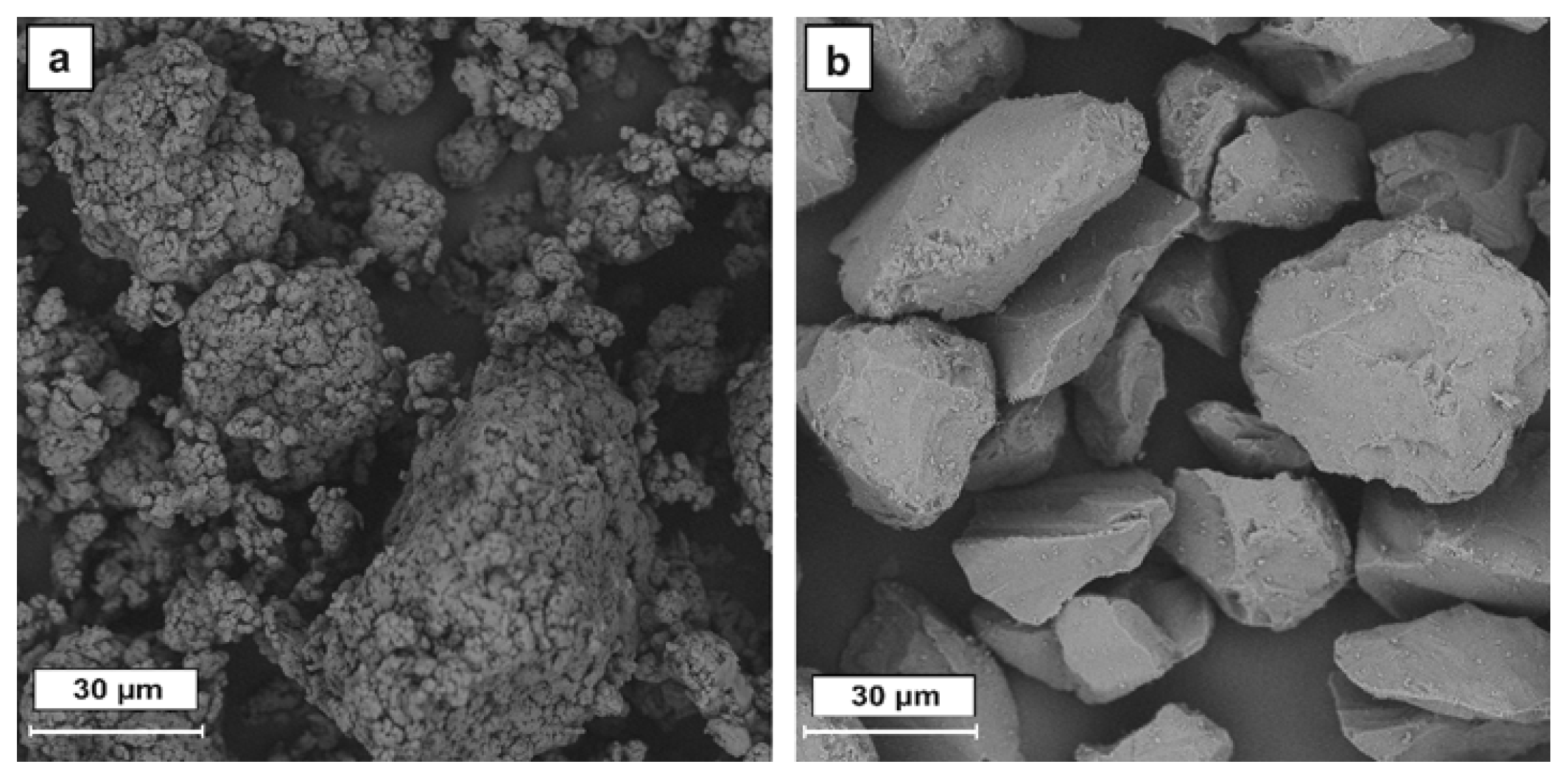
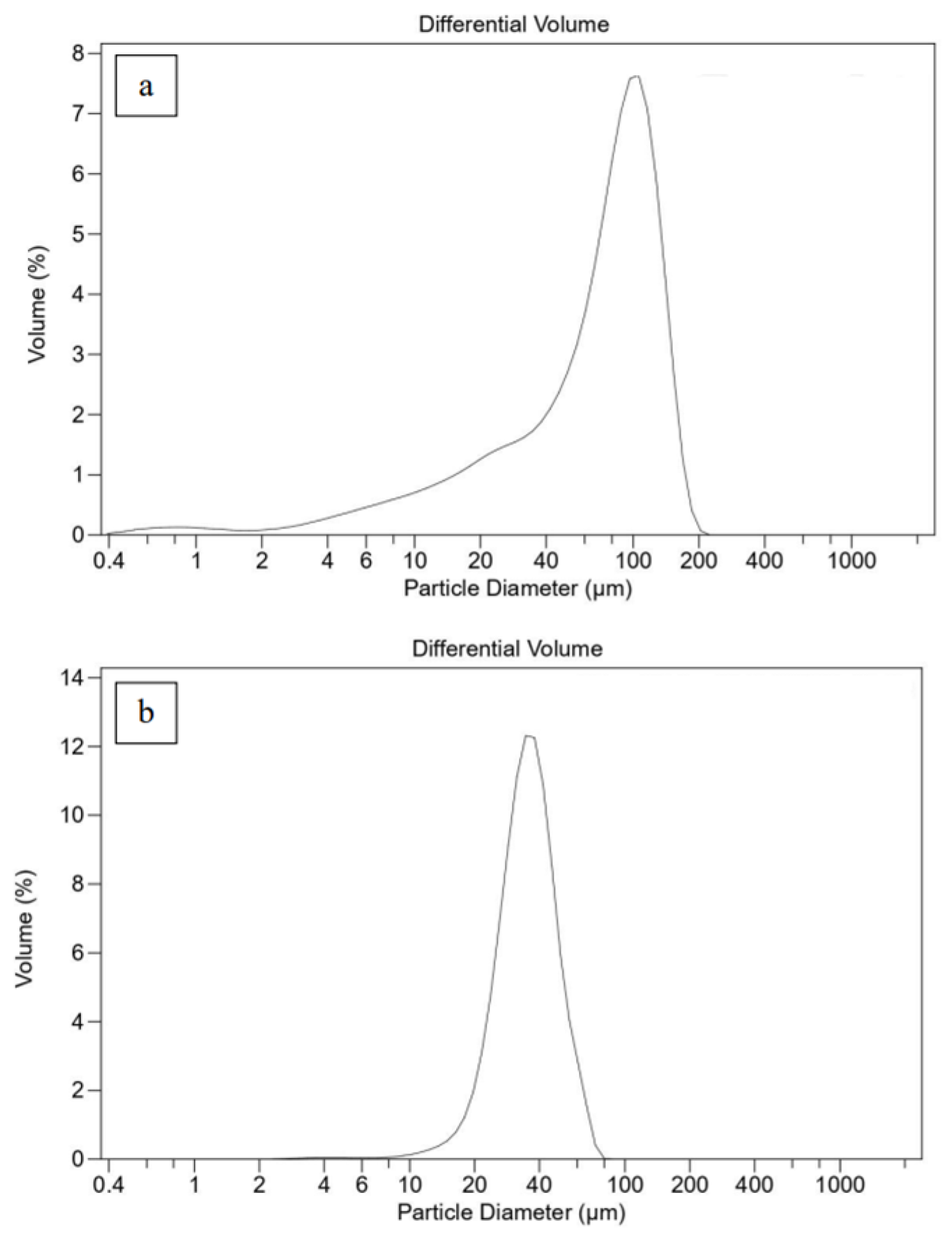
3.1. Powder Characterization

In thermal spray processes, specific criteria are established for the powder materials, including appropriate particle size and distribution. Controlling the powder’s features improves the material’s melting while preventing the significant deterioration of its structure. Additionally, the flowability of the feedstock material is crucial to facilitate uniform coating deposition [23].
ECTFE and alumina powder morphologies and particle distribution were examined using SEM and LS. Figure 1 and Figure 2 show, respectively, the ECTFE and Al2O3 powders’ morphologies and particle distribution. The results revealed that both powders have irregular shapes, which aligns with previous studies [19,24]. The Al2O3 powder consists of dense particles with sharp corners, displaying a narrow size distribution with an average particle size of 37 µm, a d10 value of 20 µm, and a d90 value of 50 µm. In contrast, ECTFE exhibits aggregated particles with a broad size distribution. The mean particle sizes, d10 and d90, are approximately 100 µm, 10 µm, and 150 µm, respectively. The LS results corroborate the SEM observations.
Furthermore, the angle of repose of the two powders was investigated. The test showed that ECTFE and Al2O3 powders have, respectively, angles of repose of 45° and 40°. This difference can be explained by the broad particle size distribution of the ECTFE powder (Figure 2), which contains both agglomerated particles and very fine particles. The presence of fine particles affects flowability, resulting in higher angles of repose. A low angle of repose indicates better flowability [25,26], facilitating continuous feeding into the thermal spray system and ensuring uniform coating deposition. The flowability of both powders was found to be suitable for application in APS equipment, allowing a continuous powder flow during the spraying process. In addition, incorporating Al2O3 in the blends slightly improved the ECTFE powder’s flowability due to its lower repose angle.
Figure 3 shows the XRD patterns of ECTFE powder and its various blends with Al2O3 on the left and the pattern of Al2O3 as a reference on the right. For pure ECTFE, a broad peak can be observed at low angles (~17° 2Ɵ), characteristic of the nature of the polymer. The XRD pattern for pure Al2O3 shows sharp and intense peaks, characteristic of the crystalline nature of alumina, and additional weaker peaks identified as Na2O·(Al2O3)11, which can result from the manufacturing process of this powder. As alumina is added to the blends, distinct narrow peaks corresponding to Al2O3 begin to appear in the patterns. As expected, the intensity of the alumina peaks increases proportionally with the concentration of Al2O3 (5%, 10%, and 15 wt.%) in the blend.

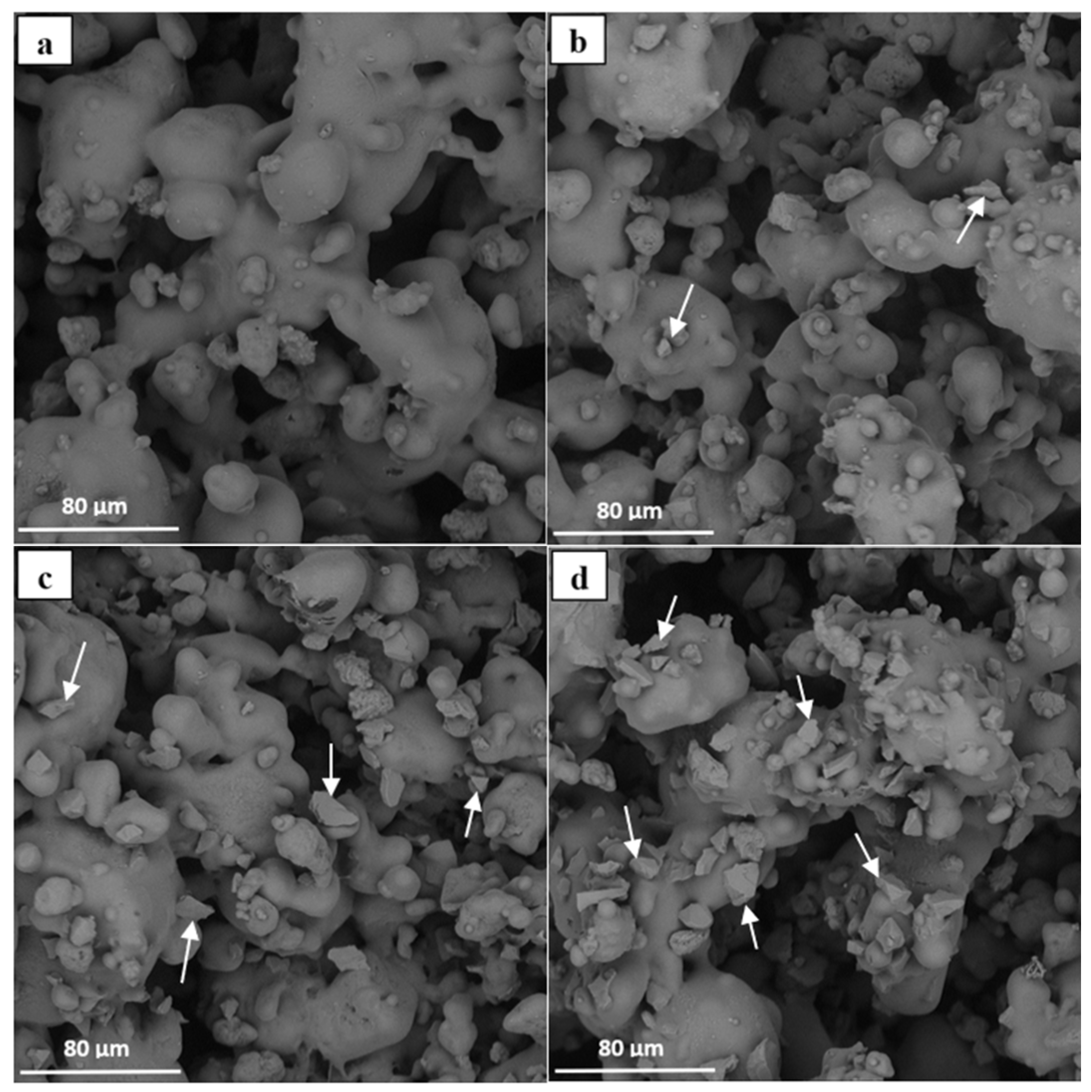
3.2. Coatings Characterization

After the deposition of the coatings, a microstructural examination was needed to evaluate the properties. This examination is important to understand the coatings’ morphology and thickness, the dispersion of ceramic particles, and potential defects.
A microstructural examination of ECTFE and the blends’ coatings was conducted using SEM. An example of the free surface of the different obtained coated samples is illustrated in Figure 4. Comparing the morphologies of the ECTFE powder (Figure 1a) and coating (Figure 4a), the fusion between the particles is clear. However, the overall morphology of the polymeric matrix suggests that not all particles fully melted. Furthermore, the integration of Al2O3 particles within the matrix was evident. As can be seen in Figure 4b–d, Al2O3 particles (marked with arrows) are well-dispersed, and their quantity increases proportionally to their percentage in the blend. Image analysis was performed on the top surface of the different coatings to semi-quantify the alumina retained in the coating. Table 3 details the percentage of the area corresponding to the ceramic material on the top surface. The top surface coatings show a gradual increase in the alumina area. This increase is related to the amount of alumina in the sprayed blends, even for the coating with more alumina content. It was observed that the alumina particles detected on the surface of the coatings have a size of up to 30 microns, suggesting that only the smaller alumina particles were successfully retained within the polymeric matrix. This observation aligns with the alumina quantification values presented in Table 3, which show that the amount of alumina detected on the surface is slightly lower than that incorporated into the sprayed blend.
It should be noticed that although the estimated temperature during the APS process was approximately 10,000–12,000 °C, the spraying conditions were specifically selected to ensure sufficiently short residence times, preventing the degradation of the polymeric material. Under these conditions, the ceramic particles did not melt, as the temperatures reached were below their melting point. Consequently, the ceramic particles were retained in the coating structure due to their interaction with the polymeric matrix. The Al2O3 particles observed in Figure 4 keep their original morphology, which indicates that there was no melting during the process. Additionally, the gradual increase in the ceramic filler content in the coatings suggests that for the prepared blends in this study, the maximum ceramic content that the coating could no longer retain was not reached.
The thickness of the coatings was examined through optical microscopic observations. All the studied coatings had a thickness near 200 µm. This result indicates that the sprayed coatings are thick, and the presence of the Al2O3 particles does not affect the coatings’ thickness, which is aligned with other studies that successfully deposited thick and dense layers of ECTFE coatings [19,27].

3.3. Coatings Adhesion Properties

The adhesion of a coating to its substrate plays a critical role in ensuring the durability and effectiveness of the coating. Without adequate adhesion, the coating may peel, crack, or delaminate prematurely. Evaluating the adhesion strength can help understand the coating’s ability to withstand mechanical forces and environmental stresses. Pull-off tests are commonly employed to evaluate the adhesion strength of the coatings. This test involves applying a controlled force perpendicular to the substrate’s surface and measuring the maximum force required to detach the coating from the substrate.
A pull-off test was used to measure the coatings’ adherence to the substrate. Table 4 provides the adhesion strength of the coatings. It was observed that incorporating ceramic powders into the blends increased the coating’s adhesion compared to pure polymeric coating. Regardless of the ceramic content, the blends had similar adhesion values. The results indicate that a relatively low ceramic content can significantly enhance adhesion properties, likely due to optimized particle dispersion [28]. Previous studies reported an adhesion strength value of around 3 MPa for polymeric coatings obtained via the sol–gel technique [11]. The improvement in adhesion strength can be attributed to the thermal spraying process, which has strong coating/substrate adhesion mechanisms [29,30].

3.4. Coating Tribology

Coatings play an important role in protecting surfaces from damage such as corrosion and wear and, therefore, enhance materials’ performance and durability in several applications. For these reasons, it is crucial to measure coatings’ wear resistance to ensure their efficiency in protecting the underlying material.
Ball-on-disc tests were conducted to determine the friction coefficients of the coatings. Figure 5 shows the curves depicting the variation in the friction coefficient over the sliding cycles, and Table 5 presents the friction coefficient values for the coatings. Most of the coatings achieved a similar friction coefficient, near 0.70, but the 15 wt.% Al2O3 coatings exhibited the lowest friction coefficient at 0.66. A lower ceramic content in the coating resulted in a slight increase in the coefficient of friction, as the ceramic particles interfered with the sliding process. In contrast, a higher concentration of ceramic particles enhanced the sliding performance by significantly improving the friction resistance and reducing the coefficient of friction. In this case, ceramic particles may enhance lubrication.
The abrasion resistance of the coatings was determined through the Taber abrasion test. Specimen initial and final weights were measured. The weight loss of the coatings is presented in Table 6. As can be observed, the coatings had almost the same weight loss, ranging from 70 to 75 mg per 1000 rev. The results imply that the amount of ceramic does not notably influence the coatings’ resistance to abrasion, which differs from prior studies where the incorporation of nanoparticle fillers improved the wear resistance [9,31]. In these coatings, there does not appear to be a notable variation in weight loss or resistance to abrasive wear related to the amount of alumina incorporated into the coating. However, similar to the results observed in the ball-on-disc tests, it seems that incorporating more than 10 wt.% Al2O3 increases wear resistance, with less mass loss compared to the case of coatings with a lower alumina content. These results, in conjunction with the friction findings, suggest that there may be a threshold for alumina content in the coating, beyond which the wear resistance of the polymeric coating might be affected.

4. Conclusions

In this study, the effect of incorporating ceramic particles into polymer coatings by APS on microstructure and wear behaviour was assessed. Four coatings were produced with the following powders: pure ECTFE, ECTFE with 5 wt.% Al2O3, ECTFE with 10 wt.% Al2O3, and ECTFE with 15 wt.% Al2O3. The optical microscopy indicated that the deposition of thick ECTFE-reinforced coatings was possible via APS. Furthermore, the microstructural examination of coatings revealed that Al2O3 particles are adequately incorporated in the polymeric matrix and that the Al2O3 content increases proportionally to its content in the powder blends. The addition of the ceramic markedly improved the adhesion of the coating, even with a low percentage of ceramic material in the blend. Regarding the wear behaviour of the ECTFE-reinforced coatings, most of the coatings had a similar friction coefficient, except for the coating with 15 wt.% Al2O3.
Taber abrasion tests indicated the minimal influence of the ceramic content on abrasion resistance. The findings of this work highlight the impact of adding ceramic to the polymeric matrix on coating performance. It contributes to the development of polymer—ceramic coatings with improved mechanical properties for various industrial applications. Further optimization of spraying parameters is recommended to enhance the coating microstructure and reduce porosity.

Author Contributions

Conceptualization, V.A.-F. and R.E.; methodology, M.A., B.G., V.A.-F. and R.E.; validation, B.G. and A.B.; formal analysis, M.A. and A.B.; investigation, M.A. and B.G.; resources, V.A.-F.; data curation, M.A. and B.G.; writing—original draft preparation, M.A. and B.G.; writing—review and editing, V.A.-F., A.B. and R.E.; supervision, V.A.-F., A.B. and R.E.; project administration, I.G.-C.; funding acquisition, I.G.-C. and R.E. All authors have read and agreed to the published version of the manuscript.

Funding

This project is carried out under the Mobidoc scheme 248 “Development of a ceramic non-stick coating, with extended formability limits on sheet metal for deep drawing applications”, funded by the EU through the EMORI program and managed by the ANPR. This study is also supported by grant PID2020-115508RB-C21, funded by MCIN/AEI/10.13039/501100011033, and, as appropriate, by “ERDF A way of making Europe”, the “European Union” or the “European Union NextGenerationEU/PRTR”. Vicente Albaladejo Fuentes is a Serra Hunter Fellow.

Data Availability Statement

The data presented in this study are available on request from the corresponding author.

Conflicts of Interest

The authors declare that they have no known competing financial interests or personal relationships that could have appeared to influence the work reported in this paper.

References

  1. McKeen, L.W. Fluorinated Coatings. In Introduction to Fluoropolymers; Elsevier: Amsterdam, The Netherlands, 2013; pp. 231–276. ISBN 978-1-4557-7442-5. [Google Scholar]
  2. Ameduri, B. Fluoropolymers: The Right Material for the Right Applications. Chem.—Eur. J. 2018, 24, 18830–18841. [Google Scholar] [CrossRef] [PubMed]
  3. Améduri, B. The Promising Future of Fluoropolymers. Macromol. Chem. Phys. 2020, 221, 1900573. [Google Scholar] [CrossRef]
  4. Deng, H.; Dong, Y.; Zhang, C.; Xie, Y.; Zhang, C.; Lin, J. An Instant Responsive Polymer Driven by Anisotropy of Crystal Phases. Mater. Horiz. 2018, 5, 99–107. [Google Scholar] [CrossRef]
  5. Zouari, S.; Ghorbel, H.; Langlade, C.; Liao, H.; Elleuch, R. Painting Process Design and Characterization of Polymer Coatings on Brass. J. Mater. Eng. Perform. 2022, 31, 180–190. [Google Scholar] [CrossRef]
  6. Briscoe, B.J. Wear of Poly (Tetrafluoroethylene) Polymer and Its Control; American Chemical Society: Washington, DC, USA, 1985; pp. 151–170. [Google Scholar]
  7. Petrovicova, E.; Knight, R.; Schadler, L.S.; Twardowski, T.E. Nylon 11/Silica Nanocomposite Coatings Applied by the HVOF Process. I. Microstructure and Morphology. J. Appl. Polym. Sci. 2000, 77, 1684–1699. [Google Scholar] [CrossRef]
  8. Petrovicova, E.; Knight, R.; Schadler, L.S.; Twardowski, T.E. Nylon 11/Silica Nanocomposite Coatings Applied by the HVOF Process. II. Mechanical and Barrier Properties. J. Appl. Polym. Sci. 2000, 78, 2272–2289. [Google Scholar] [CrossRef]
  9. Sawyer, W.G.; Freudenberg, K.D.; Bhimaraj, P.; Schadler, L.S. A Study on the Friction and Wear Behavior of PTFE Filled with Alumina Nanoparticles. Wear 2003, 254, 573–580. [Google Scholar] [CrossRef]
  10. Tomala, A.M.; Słota, D.; Florkiewicz, W.; Piętak, K.; Dyląg, M.; Sobczak-Kupiec, A. Tribological Properties and Physiochemical Analysis of Polymer-Ceramic Composite Coatings for Bone Regeneration. Lubricants 2022, 10, 58. [Google Scholar] [CrossRef]
  11. Chen, R.; Zhang, Y.; Xie, Q.; Chen, Z.; Ma, C.; Zhang, G. Transparent Polymer-Ceramic Hybrid Antifouling Coating with Superior Mechanical Properties. Adv. Funct. Mater. 2021, 31, 2011145. [Google Scholar] [CrossRef]
  12. Sagar, A.; Hemant, P. A Review on Thermal Spray Coating Processes. Int. J. Curr. Trends Eng. Res. 2016, 2, 556–563. [Google Scholar]
  13. Sampath, S. Thermal Spray Applications in Electronics and Sensors: Past, Present, and Future. J. Therm. Spray Technol. 2010, 19, 921–949. [Google Scholar] [CrossRef]
  14. Lima, R.S.; Marple, B.R. Thermal Spray Coatings Engineered from Nanostructured Ceramic Agglomerated Powders for Structural, Thermal Barrier and Biomedical Applications: A Review. J. Therm. Spray Technol. 2007, 16, 40–63. [Google Scholar] [CrossRef]
  15. Petrovicova, E.; Schadler, L.S. Thermal Spraying of Polymers. Int. Mater. Rev. 2002, 47, 169–190. [Google Scholar] [CrossRef]
  16. Zouari, S.; Ghorbel, H.; Danlos, Y.; Liao, H.; Elleuch, R. Comparative Study of HVOF-Sprayed NiCrBSi Alloy and 316L Stainless Steel Coatings on a Brass Substrate. J. Therm. Spray Technol. 2019, 28, 1284–1294. [Google Scholar] [CrossRef]
  17. Garrido, B.; Albaladejo-Fuentes, V.; Dosta, S.; Garcia-Giralt, N.; Garcia-Cano, I. 45S5/PEEK Coatings by Cold Gas Spray with In Vitro Bioactivity, Degradation, and Cellular Proliferation. J. Therm. Spray Technol. 2024, 895–911. [Google Scholar] [CrossRef]
  18. Costil, S.; Mateus, C.; Coddet, C. Ceramic/Fluoropolymer Composite Coatings by Plasma Spraying. Surf. Coat. Technol. 2006, 201, 2020–2027. [Google Scholar] [CrossRef]
  19. Leivo, E.; Wilenius, T.; Kinos, T.; Vuoristo, P.; Mäntylä, T. Properties of Thermally Sprayed Fluoropolymer PVDF, ECTFE, PFA and FEP Coatings. Prog. Org. Coat. 2004, 49, 69–73. [Google Scholar] [CrossRef]
  20. Geldart, D.; Abdullah, E.C.; Hassanpour, A.; Nwoke, L.C.; Wouters, I. Characterization of Powder Flowability Using Measurement of Angle of Repose. China Particuology 2006, 4, 104–107. [Google Scholar] [CrossRef]
  21. ISO 4624:2023; Paints and Varnishes—Pull-Off Test for Adhesion. International Organization for Standardization: Geneva, Switzerland, 2023.
  22. ASTM G99-95; Standard Test Method for Wear Testing with a Pin-on-Disk Apparatus. ASTM International: West Conshohocken, PA, USA, 1995.
  23. Pawlowski, L. The Science and Engineering of Thermal Spray Coatings; John Wiley & Sons: Hoboken, NJ, USA, 2008; ISBN 0-470-75407-9. [Google Scholar]
  24. Perumal, G.; Geetha, M.; Asokamani, R.; Alagumurthi, N. A Comparative Study on the Wear Behavior of Al2O3 and SiC Coated Ti-6Al-4V Alloy Developed Using Plasma Spraying Technique. Trans. Indian Inst. Met. 2013, 66, 109–115. [Google Scholar] [CrossRef]
  25. Cañas, E.; Vicent, M.; Bannier, E.; Carpio, P.; Orts, M.J.; Sánchez, E. Effect of Particle Size on Processing of Bioactive Glass Powder for Atmospheric Plasma Spraying. J. Eur. Ceram. Soc. 2016, 36, 837–845. [Google Scholar] [CrossRef]
  26. Lv, S.; Zhang, J.; Ni, H.; Wang, X.; Zhu, Y.; Gu, T. Study on Preparation of Aluminum Ash Coating Based on Plasma Spray. Appl. Sci. 2019, 9, 4980. [Google Scholar] [CrossRef]
  27. Bosh, N.; Deggelmann, L.; Blattert, C.; Mozaffari, H.; Müller, C. Synthesis and Characterization of Halar® Polymer Coating Deposited on Titanium Substrate by Electrophoretic Deposition Process. Surf. Coat. Technol. 2018, 347, 369–378. [Google Scholar] [CrossRef]
  28. Robotti, M.; Dosta, S.; Fernández-Rodríguez, C.; Hernández-Rodríguez, M.J.; Cano, I.G.; Melián, E.P.; Guilemany, J.M. Photocatalytic Abatement of NOx by C-TiO2/Polymer Composite Coatings Obtained by Low Pressure Cold Gas Spraying. Appl. Surf. Sci. 2016, 362, 274–280. [Google Scholar] [CrossRef]
  29. Li, C.-J.; Luo, X.-T.; Yao, S.-W.; Li, G.-R.; Li, C.-X.; Yang, G.-J. The Bonding Formation during Thermal Spraying of Ceramic Coatings: A Review. J. Therm. Spray Technol. 2022, 31, 780–817. [Google Scholar] [CrossRef]
  30. Sobolev, V.V.; Guilemany, J.M.; Nutting, J.; Miquel, J.R. Development of Substrate-Coating Adhesion in Thermal Spraying. Int. Mater. Rev. 1997, 42, 117–136. [Google Scholar] [CrossRef]
  31. Wetzel, B.; Haupert, F.; Zhang, M.Q. Epoxy Nanocomposites with High Mechanical and Tribological Performance. Compos. Sci. Technol. 2003, 63, 2055–2067. [Google Scholar] [CrossRef]
Figure 1. Powder morphologies: (a) ECTFE and (b) Al2O3.
Jmmp 09 00050 g001
Figure 2. Powder particle distributions: (a) ECTFE and (b) Al2O3.
Jmmp 09 00050 g002
Figure 3. XRD patterns of original powders and blends.
Jmmp 09 00050 g003
Figure 4. Morphologies of the different coatings: (a) ECTFE; (b) ECTFE + 5 wt.% Al2O3; (c) ECTFE + 10 wt.% Al2O3; and (d) ECTFE + 15 wt.% Al2O3. (Arrows indicate the ceramic particles embedded in the polymeric matrix for all the coatings containing Al2O3).
Jmmp 09 00050 g004
Figure 5. Ball-on-disc test curves.
Jmmp 09 00050 g005
Table 1. Properties of ECTFE.
Density (g/cm3)Tensile Stress at Break (MPa)Flexural Strength (MPa)Hardness, Shore D
1.6840–5745–5570–75
Table 2. Optimized plasma spraying parameters.
Spraying Parameters
Primary gas (Ar) flow rate (slpm)95
Secondary gas (H2) flow rate (slpm)1
Carrier gas (Ar) flow rate (slpm)7
Voltage (V)55.5
Arc current (A)300
Traverse gun speed (mm/s)500
Stand-off distance (mm)100
Spraying cycles3
Table 3. Characterization of coatings. Semi-quantitative composition and thickness values.
CoatingSemi-Quantification of Al2O3 (%)Thickness (µm)
ECTFE0.0 ± 0.0205 ± 12
ECTFE + 5 wt.% Al2O31.5 ± 0.3198 ± 17
ECTFE + 10 wt.% Al2O33.5 ± 0.5213 ± 13
ECTFE + 15 wt.% Al2O34.2 ± 0.2194 ± 10
Table 4. Adhesion strength results.
CoatingECTFEECTFE + 5 wt.% Al2O3ECTFE + 10 wt.% Al2O3ECTFE + 15 wt.% Al2O3
Bond strength (MPa)7.5 ± 0.910.1 ± 0.910.1 ± 0.89.3 ± 1.3
Table 5. Friction coefficient of the different coatings.
CoatingECTFEECTFE + 5 wt.% Al2O3ECTFE + 10 wt.% Al2O3ECTFE + 15 wt.% Al2O3
Friction. Co0.68 ± 0.010.71 ± 0.010.72 ± 0.010.66 ± 0.01
Table 6. Taber abrasion test results.
CoatingECTFEECTFE + 5 wt.% Al2O3ECTFE + 10 wt.% Al2O3ECTFE + 15 wt.% Al2O3
Weight loss (mg/1000 rev)73.8 ± 2.272.6 ± 2.5 74.6 ± 1.770.7 ± 3.8
Disclaimer/Publisher’s Note: The statements, opinions and data contained in all publications are solely those of the individual author(s) and contributor(s) and not of MDPI and/or the editor(s). MDPI and/or the editor(s) disclaim responsibility for any injury to people or property resulting from any ideas, methods, instructions or products referred to in the content.

