Article

A Finite Element Analysis Study of Influence of Femoral Stem Material in Stress Shielding in a Model of Uncemented Total Hip Arthroplasty: Ti-6Al-4V versus Carbon Fibre-Reinforced PEEK Composite

1
Department of Mechanics, Mathematics and Management, Polytechnic of Bari, 70125 Bari, Italy
2
Department of Translational Biomedicine and Neuroscience, University of Bari “Aldo Moro”, Policlinic Piazza G. Cesare, 11, 70124 Bari, Italy
*
Author to whom correspondence should be addressed.
J. Compos. Sci. 2024, 8(7), 254; https://doi.org/10.3390/jcs8070254
Submission received: 26 April 2024 / Revised: 19 June 2024 / Accepted: 23 June 2024 / Published: 2 July 2024
(This article belongs to the Special Issue Carbon Fiber Composites, Volume III)

Abstract

:
Total hip arthroplasty is one of the most common and successful orthopaedic operations. Occasionally, periprosthetic osteolysis associated with stress shielding occurs, resulting in a reduction of bone density where the femur is not properly loaded and the formation of denser bone where stresses are confined. To enhance proximal load transfer and reduce stress shielding, approaches, including decreasing the stiffness of femoral stems, such as carbon fibre-reinforced polymer composites (CFRPCs), have been explored through novel modular prostheses. The purpose of the present study was to analyse, by the finite element analysis (FEA) method, the effect that the variation of material for the distal part of the femoral stem has on stress transmission between a modulable prosthesis and the adjacent bone. Methods: Through three-dimensional modelling and the use of commercially available FEA software Ansys R2023, the mechanical behaviour of the distal part of the femoral stem made of CFRPC or Ti-6Al-4V was obtained. A load was applied to the head of the femoral stem that simulates a complete walking cycle. Results: The results showed that the use of a material with mechanical characteristics close to the bone, like CFRPC, allowed for optimisation of the transmitted loads, promoting a better distribution of stress from the proximal to the distal part of the femur. This observation was also found in some clinical studies in literature, which reported not only an improved load transfer with the use of CFRPC but also a higher cell attachment than Ti-6Al-4V. Conclusions: The use of a material that has mechanical properties that are close to bone promotes load transfer from the proximal to the distal area. In particular, the use of CFRPC allows the material to be designed based on the patient’s actual bone characteristics. This provides a customised design with a lower risk of prosthesis loss due to stress shielding.

1. Introduction

The hip joint, also called the coxofemoral joint, plays a key function in providing dynamic support for the body’s weight and transmitting loads that are distributed from the skeletal axis to the lower limbs [1,2,3]. However, the hip joint is exposed to various risks and damage that can lead to pathological conditions [4,5,6,7,8]. In some cases where the joint is severely compromised by diseases such as osteoarthritis or complex fractures of the femoral head or bone tumours, it may be necessary to surgically replace the joint with a prosthetic device [9,10,11,12,13,14,15]. This surgery can be a total hip joint replacement (total hip arthroplasty, THA), which involves removing both the femoral head and the acetabulum of the patient, or a partial replacement (hemi-replacement) in which only part of the joint is replaced [16]. Generally, titanium alloys, such as Ti-6Al-4V, are used for the femoral stems due to their lightweight, corrosion resistance and biocompatibility [17,18]. These alloys offer good dynamic mechanical strength and show high success rates [19]. The prosthesis, when inserted, transfers the load from the femoral head and acetabular cavity at the hip to the prosthesis itself [20,21,22,23,24]. This can affect the biomechanics of the joint and the surrounding bone. In particular, the stress applied to the bone may promote its physiological remodelling [25,26,27,28,29]. In fact, when a prosthesis is introduced into the bone, the distribution of loads is altered, causing atrophic bone to form in unloaded areas and denser bone in overloaded areas. This is due to the different stiffnesses between the bone and the prosthetic materials, with metals having a higher stiffness [29]. For example, cortical bone has a modulus of elasticity of about 16 GPa, while common materials used for prostheses, such as stainless steel, have a modulus of elasticity of about 200 GPa [30]. This considerable difference causes what is called stress shielding. To mitigate the effects of stress shielding, it is important to design prostheses that better mimic the biomechanical properties of natural bone and allow for a more even distribution of mechanical load on the surrounding bone. In this respect, the development of modular prostheses has made it possible to adjust implant stiffness or to select components that reduce stress shielding, allowing a better distribution of load on the surrounding bone [31]. In addition, the choice of modular part materials with properties like natural bone can help reduce the risk of stress shielding. In a study of 118 patients undergoing femur reconstruction using a modular femoral stem system, it was found that distal bone fixation was achieved in 100% of patients, the offset was corrected in 66%, leg length discrepancy was corrected in 78%, and stability was achieved in 97% of cases [32]. The suggested solution to this complication is to use a less rigid material with mechanical properties close to the properties of bone, for example, using porous structures of the femoral stems. In a study conducted by Hou et al. [33] where, using a porous honeycomb structure of the femoral stem in Ti-6Al-4V, stress shielding was reduced by adaptation of Young’s modulus. In another study by Thomas et al. [34], the use of 3D-printed Ti6Al4V additive manufacturing lattice structures provided an elastic modulus of 15.7 GPa and yield strength of 296 MPa, values very similar to bone. This resulted in improved stress transfer between bone and femoral stem and reduced stress shielding. Krishna et al. [35] introduced a porous titanium implant with reduced stiffness (2–45 GPa) by a laser-assisted lattice structure. A reduction in stress shielding was observed with this technique. The use of materials with mechanical properties like bone, such as composites, could solve the stress shielding problem. For example, the use of (CF/PEEK) has an elastic modulus that can vary depending on processing and be very close to the values of the femoral bone. Finite Element Analysis (FEA) can be used to evaluate how stress is distributed in the bone and prosthesis, identify potential areas of stress shielding, and optimise the design of the prosthesis to reduce them [36,37]. However, nowadays, there are many studies on the optimisation of stress shielding for Ti-6Al-4V femoral stems, but few have evaluated the effect of stress shielding using composite materials such as CFRP combined with metallic materials such as Ti-6Al-4V through modularity [38,39]. Therefore, in this study, the effect of stress shielding with a femoral stem with a distal section made of carbon fibre-reinforced polymer composites CFRPC was analysed using finite element analysis, and the results were compared with a femoral stem made of Ti6Al4V. CFRP was chosen as the composite material because it is known for its high strength and stiffness while being lightweight. It also offers the possibility of designing femoral stems with complex shapes and geometries, allowing more accurate customisation and adaptation to the anatomical needs of the patient, helping to reduce the phenomenon of stress shielding, as its modulus of elasticity can be designed to be close to that of the surrounding bone. The null hypothesis was that the use of a CFRPC would produce a more homogeneous stress distribution on the bone from the proximal end to the distal end than when Ti-6Al-4V is used.

2. Materials and Methods

The 3D model of the femoral prosthesis was constructed using Autodesk Inventor 3D 2024 software. Figure 1 shows the main dimensions of the model and the two configurations using an interchangeable distal part with a circular cross-section.
The three-dimensional (3D) geometric model of the healthy femur and the femur with prosthesis is shown in Figure 2a,b, which corresponds to a two-dimensional cut through the entire femur in the mid-frontal plane for both in the case of a healthy femur (HF) and a femur with prosthesis (FP). Subsequently, cortical and trabecular tissue thicknesses were obtained from previous studies [40,41] and compared with standard anatomical femur dimensions (Figure 2a) [41]. After that, the simplified model of the femur was constructed using Autodesk Inventor 3D 2024 software, and through the Boolean operation, the cavity inside the femur was created to reflect the external geometry of the prosthesis. Then, with the assembly operation, the prosthesis was inserted inside the modular canal Figure 2b,c.
The model was then saved in stp format and transferred into the FEA software Ansys R2023 (ANSYS Workbench). Ti-6Al-4V alloy, cortical bone, and cancellous bone were each considered to have linearly isotropic and homogeneous elastic properties (Table 1) [42,43,44,45].
For the CFRPC, the mechanical properties are influenced by the mechanical characteristics of the fibre but also by the orientation of the fibres between the individual layers. In this study, configuration I was chosen in which the fibres are oriented at 0, +45, −45 and 90 degrees, which allows an optimal distribution of the applied load and a homogeneous mechanical behaviour in the system (Figure 3). This type of fibre orientation helps to distribute the applied load and to transfer it to the bone. Furthermore, with this configuration, the mechanical behaviour is transversely isotropic [45]. In addition, a fibre volume fraction of approximately 60% was chosen. This percentage represents the critical volume below in which the mechanical properties of the composite would be lower than that of the matrix.
The relevant mechanical properties of the configuration of the CFRPC are given in Table 2 [45].

2.1. Meshing

The model was constructed with 516,752 quadratic tetrahedral elements Figure 4, adopting an average element size of 0.5 mm, as reported in [43]. Based on the chosen mesh, a convergence test was carried out to test the reliability of the results based on the number of elements with which the 3D model was discretised (Figure 5).
In the convergence test conducted in Figure 5, the von Mises stress error with a mesh of 0.5 mm is 0.2% compared to a 0.4 mm mesh.

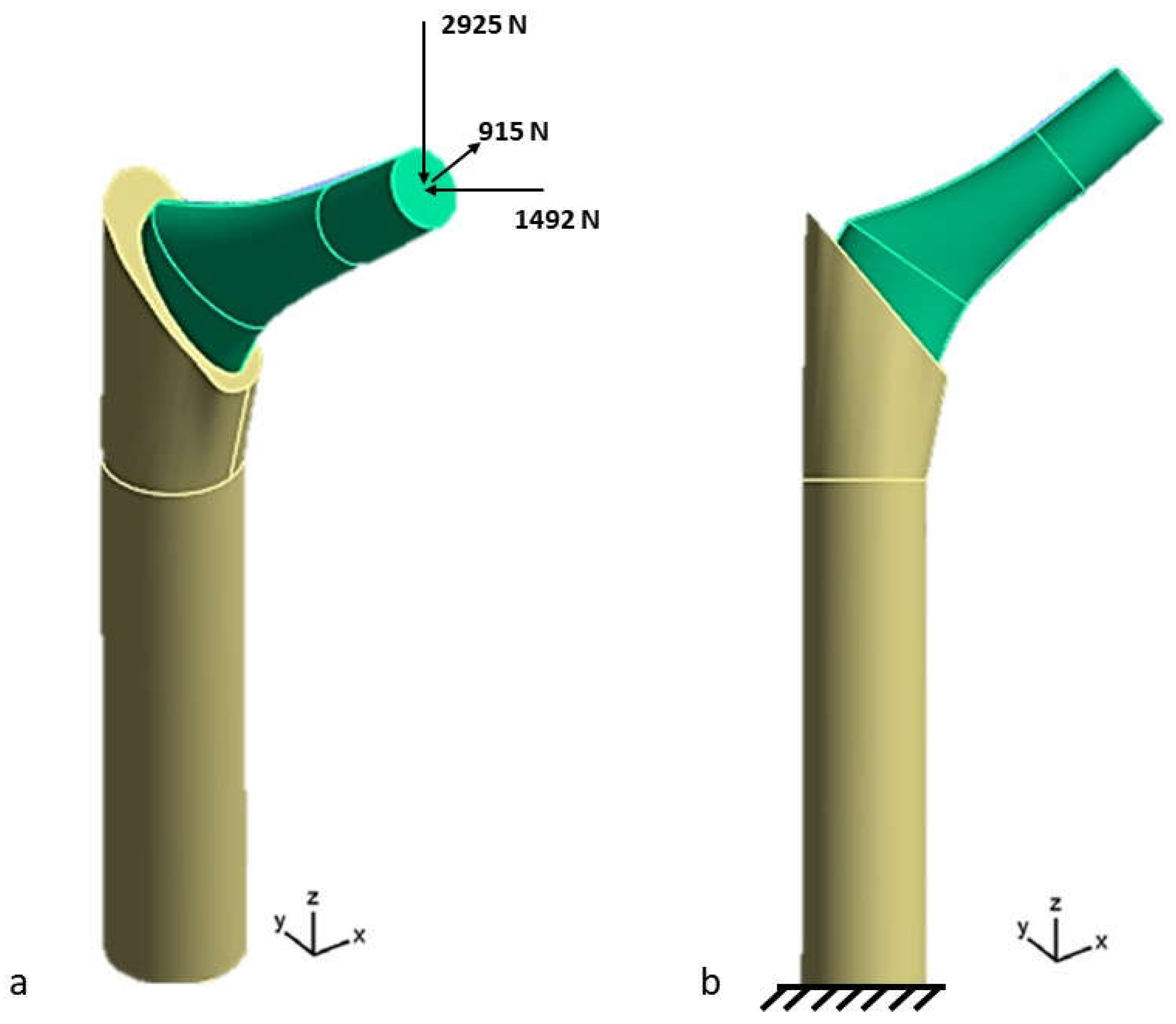
2.2. Loads and Boundary Conditions

The loading condition was considered as a gait cycle on a plane with an average speed of 1.1 m/s [45], which consisted of the loads on the femoral head [4.5 times body weight with force components (x, y, z) (1492, 915, 2925) N] [46]. Consequently, the lower surface of the femur was constrained in all directions (x, y, z) Figure 6 [46]. In addition, to simulate the contact conditions between bone and femoral stem after insertion, a fixed contact interface between bone and femoral stem was defined. For this purpose, surface-to-surface contact elements were used, which do not allow separation and sliding from the proximal zone to the distal zone of the femoral stem. All solutions were processed with ANSYS WORKBENCH R 2023 (ANSYS Inc., Canonsburg, PA, USA).

Calculation of Stress Shielding

The insertion of the prosthesis into the femur generates a reduction in stress in the proximal area because most of the load bypasses this area and is directly transmitted from the femoral stem to the distal portion of the femur. Weinans et al. [47] defined stress shielding may be expressed as a function of stress in the proximal zone of the femur. The finite element method can be used to identify the design solution that best limits the stress shielding phenomenon. In this study, in the absence of an accurate model of the real femoral bone, the effect of stress shielding was evaluated by comparing the two materials for the femoral stem. Specifically, the stress on the bone is evaluated using a prosthesis made of Ti-6Al-4V and one with a distal part made of CFRPC. In addition, muscle insertion forces were not considered in this study because the analysis mainly focuses on the forces exchanged between the femoral stem and bone in the distal and proximal areas. In a future study, the effect of the stress shield will be evaluated using a real femoral bone as a model, including muscle insertion forces.

3. Results

The analysis of the results was carried out considering the von Mises equivalent stress criterion. The von Mises criterion is used in the FEA analysis of a femoral stem because it provides an accurate and reliable assessment of the failure behaviour of ductile materials under complex loads, thus helping to ensure the safety and effectiveness of the prosthetic implant. Figure 7 shows the von Mises stress results of the 3D model consisting of the femoral stem with the two configurations of the distal part in CFRPC and Ti6-Al-4V inserted inside the femur.
Figure 7 shows that the von Mises stress is higher when a modular prosthesis is used, with the proximal and distal parts made of the same material (Ti-6Al-4V) Figure 7a. Specifically, the maximum stress obtained at the implant is 725.25 MPa in the first case and 235.69 MPa in the case where the material of the distal component is CFRPC Figure 7b. In case (a), the stress distribution is mainly absorbed by the prosthesis; in fact, a first analysis shows that the bone in contact with the prosthesis in the proximal zone does not seem to be adequately stimulated. Moreover, in case (a), the distal zone of the femur is subjected to a greater load than the proximal zone. This makes it clear that the phenomenon of stress shielding is greater in the first case than in the second, using a distal part of the CFRPC prosthesis, where a more even distribution of stresses is observed between the femoral stem and the adjacent bone (Figure 7b).
Figure 8 shows the distribution of von Mises stresses calculated along a path (red line) of the femur section. In the case where the distal part of the implant is made of Ti-6Al-4V (Figure 8a), the stress in the proximal zone of the bone is 6.21 MPa, but in the central zone, there is an increase in stress. For example, at 70 mm from the distal zone, the stress is 37.25 MPa. However, in the distal zone, the stress increases, reaching 78.5 MPa. On the other hand, the distribution and trend of the von Mises stress in the case where a distal component of the implant made of CFRPC is used shows significant differences compared to the previous case. In fact, it is observed that the stress in the proximal zone may be 17 MPa compared to 6.21 MPa. Considering 70 mm from the distal zone, the stress is 26.75 MPa. While in the distal zone, stress values of approximately 67.25 MPa are reached compared to 78.5 MPa. This shows how the use of a distal CFRPC component, which has a stiffness similar to that of bone, allows a more even distribution of stress from the proximal to the distal zone.

Stress Shielding Evaluation

In this study, Gruen’s seven periprosthetic zones were considered for stress shielding analysis, in which the tip of the lesser trochanter defines the distal boundary of zones 1 and 7. The midpoint between the lesser trochanter and the bottom tip of the femoral stem defines the limit between zone 2 and zones 3, 5 and 6. Zone 4 represents the total bone area located 20 mm distal to the tip of the femoral stem. Vertically, the central axis of the femur divides the medial and lateral zones (Figure 9).
At a specified Gruen zone, the stress shielding factor was defined as the ratio of the von Mises stress at the zone when the distal part of the femoral stem was made of CFRPC to von Mises stress at the zone when the distal part of the femoral stem was made of Ti-6Al-4V. Thus, it is desirable for the factor to be >1 in the proximal region (Gruen zones 1 and 7) and <1 in the distal region (Gruen zone 4). The present results (Table 3) demonstrate this.
From Table 3, using a distal CFRPC part for a femoral stem, the shielding stress factor is 1.34 in the proximal zone (Gruen zone 1). While in the distal zone (Gruen zone 4), the stress shielding factor is 0.85. This analysis, therefore, showed that the use of a distal part of the femoral stem in CFRPC improved the stress distribution by promoting greater stress in the proximal zone (Gruen zones 1 and 7).

4. Discussion

The use of carbon fibre-reinforced polymer composites CFRPC allows mechanical properties comparable to those of bone in terms of stiffness, contributing to the reduction of the stress shielding phenomenon [48]. The mechanical properties of these materials depend on the orientation and amount of carbon fibres in the composite matrix, with strength ranging from 70 to 1900 MPa and stiffness from 10 to 100 GPa. In addition, CFRPC composites have demonstrated excellent biocompatibility, environmental stability, and chemical resistance [49,50,51]. Nakahara et al. [51] studied the results of uncemented and cemented CFRPC hip prostheses in sheep femoral bone, observing the strength at different loading levels without significant stress shielding effect. Hacking et al. [52] evaluated the tissue response to a hydroxy-apatite-coated composite femoral implant, showing positive bone apposition and no adverse reactions. Scotchford et al. [53] demonstrated good biocompatibility of carbon fibre-based composites through cell attachment and proliferation studies. However, few studies have been conducted using the finite element method, which allows quantitative evaluation of stress transmission on bone tissue and then analyses the effect of stress shielding for different material configurations, shapes and structures of femoral stems. Specifically, a numerical finite element analysis (FEA) performed by Ayham Darwich et al. [54] evaluated the effect of stress shielding on hip prosthesis stems coated with composite (carbon/PEEK) and polymer (PEEK) materials. The results of the study showed that the use of coating materials such as PEEK on a CFRPC femoral stem can reduce the effect of stress shielding. In a numerical study conducted by Akay et al. [55] analysing the stress distribution in a Ti-6Al-4V and CFRPC cemented prosthesis, the authors showed that in the case of CFRPC, the transfer occurred over a larger surface area, thus potentially reducing local stress. In another finite element analysis (FEA) study, Caouette et al. [56] evaluated the performance of a biomimetic hip stem made of a hydroxyapatite-coated carbon fibre composite. Compared to the Ti-6Al-4V stem, the CFRPC femoral stem allowed reduced stress shielding. However, early failure of a CFRPC implant due to inadequate fixation and fracture of the femoral stem was observed in a study by Allcock et al. [57] inadequate fixation is due to the inability of the CFRPC stem to provide surfaces for bone growth and allow adequate osseointegration. Nowadays, modularity between prosthetic components, such as the proximal and distal part of the femoral stem, is used to provide greater versatility in the choice of sizes, lengths and angles of prosthetic components, allowing for better anatomical adaptability and more precise joint alignment in procedures such as total hip or total knee arthroplasty [58,59]. However, it is important to note that excessive modularity can lead to additional risks, such as the potential for component damage, accelerated wear, and the possibility of fractures or other complications related to the interface between different modular components [60]. The idea of modularity was explored in this study using numerical finite element analysis to evaluate the effect of stress shielding on a full Ti-6Al-4V femoral stem and a femoral stem with an interchangeable CFRPC distal section. Only one in vitro study by Bennett et al. [61] was found in the literature, which showed that the femoral stem with a CFRP distal part provided an increase in proximal bone density and a reduction in distal bone density, with promising results at 10 years of follow-up and clinical outcomes like those of an all-metal stem. Therefore, in this study, from a stress point of view, an improvement in stress shielding reduction was obtained by using a distal part of the femoral stem made of CFRPC. In fact, the results showed that with this configuration, the stress shielding factor was 1.34 in the proximal zone and 0.85 in the distal zone of the prosthesis. This finding proves that the stress distribution was more concentrated in the proximal area, thus promoting bone remodelling. From a clinical point of view, the results presented in this work allow the perfect combination of the constituent materials of the femoral stem through modularity. Promoting better stress distribution and reducing the problem of stress shielding. However, the distal part of the femoral stem can be anatomically adapted to the shape of the femur, improving stability and connection with the surrounding bone. The current study is limited by the use of isotropic mechanical properties for the bone model, which may not fully capture the anisotropic nature of bone. Future research should consider the real anisotropic properties for more accurate modelling. In addition, modularity can increase the risk of corrosion between prosthetic components due to the increased complexity of the interface and stresses that can cause micro-fretting, leading to loss of connection between components [62,63]. However, in this study, the contact between the modular parts of the femoral stem was fixed, as the study focused on evaluating stress in the surrounding bony tissues. In addition, another limitation of this study is the application of a static load to the femoral stem. Further studies should consider the effect of variable loading during the gait cycle and the influence of different materials in the modularity of the connection with other components of the femoral stem. Finally, based on the results obtained in this FEA analysis, an evaluation by in vitro tests will be necessary to validate the modelling performed in this study.

5. Conclusions

The Finite Element Method (FEM) was developed and applied for stress analysis and stress shielding evaluation of a modular femoral stem with a distal part made of Ti-6Al-4V or CFRPC. Using the concept of modularity, the distal part of the femoral stem can be designed with innovative materials such as CFRPC to adapt the mechanical properties of the prosthesis to the bone by reducing the risk of stress shielding. The results obtained from this study show that using a distal part made of CFRPC contributes to an increase in stress in the proximal part of the femur with a stress shielding factor of 1.34 and 0.85 in the distal part. In addition, the maximum stresses obtained are lower than those obtained using a femoral stem made entirely of Ti-6Al-4V. These results provide a basis for appropriate validation through in vitro testing.

Author Contributions

Conceptualisation, M.C. and B.T.; methodology, M.C.; software, M.C.; validation, B.T. and G.S. formal analysis, M.C. and B.T.; investigation, M.C.; resources, M.C. and B.T.; data curation, M.C.; writing—original draft preparation, M.C. and B.T.; writing—review and editing, M.C., B.T., G.S. and G.D.G.; visualisation, B.T., G.S., G.G., G.D.G. and M.T.; supervision, G.S. and B.T.; project administration, G.S. and B.T. All authors have read and agreed to the published version of the manuscript.

Funding

This research received no external funding.

Data Availability Statement

All experimental data to support the findings of this study are available by contacting the corresponding author upon request.

Conflicts of Interest

The authors declare no conflicts of interest.

References

  1. Knight, S.R.; Aujla, R.; Biswas, S.P. Total Hip Arthroplasty—Over 100 years of operative history. Orthop. Rev. 2011, 3, 16. [Google Scholar]
  2. Ridzwan, M.I.Z.; Shuib, S.; Hassan, A.Y.; Shokri, A.A.; Mohamad Ibrahim, M.N. Problem of Stress-shielding and Improvement to the Hip Implant Designs: A Review. J. Med. Sci. 2007, 7, 460–467. [Google Scholar] [CrossRef]
  3. Babaei, N.; Hannani, N.; Dabanloo, N.J.; Bahadori, S. A systematic review of the use of commercial wearable activity trackers for monitoring recovery in individuals undergoing total hip replacement surgery. Cyborg Bionic Syst. 2022, 2022, 9794641. [Google Scholar] [CrossRef]
  4. Duffy, S.; Gelfer, Y.; Trompeter, A.; Clarke, A.; Monsell, F. The clinical features, management options and complications of paediatric femoral fractures. Eur. J. Orthop. Surg. Traumatol. 2021, 31, 883–892. [Google Scholar] [CrossRef] [PubMed]
  5. Zhang, B.; Liu, S.; Liu, Z.; Liu, B.; Huo, J.; Li, M.; Han, Y. Clinical and radiologic outcomes in patients undergoing primary total hip arthroplasty with Collum Femoris Preserving stems: A comparison between the direct anterior approach and the posterior approach. BMC Musculoskelet. Disord. 2022, 23, 77. [Google Scholar] [CrossRef]
  6. Rodrigues, L.; Cornelis, F.H.; Chevret, S. Hip Fracture Prevention in Osteoporotic Elderly and Cancer Patients: An On-Line French Survey Evaluating Current Needs. Medicina 2020, 56, 397. [Google Scholar] [CrossRef] [PubMed]
  7. Rozell, J.C.; Donegan, D.J. Periprosthetic Femur Fractures Around a Loose Femoral Stem. J. Orthop. Trauma. 2019, 33, S10–S13. [Google Scholar] [CrossRef] [PubMed]
  8. Ransohoff, C.B.; Wanner, R.; Solinger, T.; Gautier, E.; Eijer, H.; Wahl, P. The different failure modes of the connecting elements of the modular hip arthroplasty revision stem Revitan. J. Mech. Behav. Biomed. Mater. 2021, 123, 104778. [Google Scholar]
  9. Bischoff, P.; Kramer, T.S.; Schröder, C.; Behnke, M.; Schwab, F.; Geffers, C.; Aghdassi, S.J.S. Age as a risk factor for surgical site infections: German surveillance data on total hip replacement and total knee replacement procedures 2009 to 2018. Eurosurveillance 2023, 28, 2200535. [Google Scholar] [CrossRef]
  10. Goodman, S.M.; Mehta, B.Y.; Mandl, L.A.; Szymonifka, J.D.; Finik, J.; Figgie, M.P.; Singh, J.A. Validation of the hip disability and osteoarthritis outcome score and knee injury and osteoarthritis outcome score pain and function subscales for use in total hip replacement and total knee replacement clinical trials. J. Arthroplast. 2020, 35, 1200–1207. [Google Scholar] [CrossRef]
  11. Perticarini, L.; Rossi, S.M.; Benazzo, F. Unstable total hip replacement: Why? Clinical and radiological aspects. Hip Int. 2020, 30, 37–41. [Google Scholar] [CrossRef] [PubMed]
  12. Ray, G.S.; Ekelund, P.; Nemes, S.; Rolfson, O.; Mohaddes, M. Changes in health-related quality of life are associated with patient satisfaction following total hip replacement: An analysis of 69,083 patients in the Swedish Hip Arthroplasty Register. Acta Orthop. 2020, 91, 48–52. [Google Scholar] [CrossRef] [PubMed]
  13. Kim, J.S.; Moon, N.H.; Do, M.U.; Jung, S.W.; Suh, K.T.; Shin, W.C. The use of dual mobility acetabular cups in total hip replacement reduces dislocation rates in hip dysplasia patients. Sci. Rep. 2023, 13, 22404. [Google Scholar] [CrossRef] [PubMed]
  14. Hao, Y.; Wang, L.; Jiang, W.; Wu, W.; Ai, S.; Shen, L.; Dai, K. 3D printing hip prostheses offer accurate reconstruction, stable fixation, and functional recovery for revision total hip arthroplasty with complex acetabular bone defect. Engineering 2020, 6, 1285–1290. [Google Scholar] [CrossRef]
  15. Hevesi, M.; Wyles, C.C.; Rouzrokh, P.; Erickson, B.J.; Maradit-Kremers, H.; Lewallen, D.G.; Berry, D.J. Redefining the 3D topography of the acetabular safe zone: A multivariable study evaluating prosthetic hip stability. JBJS 2022, 104, 239–245. [Google Scholar] [CrossRef] [PubMed]
  16. Lakstein, D.; Eliaz, N.; Levi, O.; Backstein, D.; Kosashvili, Y.; Safir, O.; Gross, A.E. Fracture of cementless femoral stems at the mid-stem junction in modular revision hip arthroplasty systems. J. Bone Jt. Surg. 2011, 93, 57–65. [Google Scholar] [CrossRef] [PubMed]
  17. Cassar-Gheiti, A.J.; McColgan, R.; Kelly, M.; Cassar-Gheiti, T.M.; Kenny, P.; Murphy, C.G. Current concepts and outcomes in cemented femoral stem design and cementation techniques: The argument for a new classification system. EFORT Open Rev. 2020, 5, 241–252. [Google Scholar] [CrossRef]
  18. Al Zoubi, N.F.; Tarlochan, F.; Mehboob, H.; Jarrar, F. Design of titanium alloy femoral stem cellular structure for stress shielding and stem stability: Computational analysis. Appl. Sci. 2022, 12, 1548. [Google Scholar] [CrossRef]
  19. Zajc, J.; Moličnik, A.; Fokter, S.K. Dual modular titanium alloy femoral stem failure mechanisms and suggested clinical approaches. Materials 2021, 14, 3078. [Google Scholar] [CrossRef]
  20. Mavčič, B.; Antolič, V. Cementless femoral stem fixation and leg-length discrepancy after total hip arthroplasty in different proximal femoral morphological types. Int. Orthop. 2021, 45, 891–896. [Google Scholar] [CrossRef]
  21. Radaelli, M.; Buchalter, D.B.; Mont, M.A.; Schwarzkopf, R.; Hepinstall, M.S. A new classification system for cementless femoral stems in total hip arthroplasty. J. Arthroplast. 2023, 38, 502–510. [Google Scholar] [CrossRef] [PubMed]
  22. Springer, B.D.; Hubble, M.J.; Howell, J.R.; Moskal, J.T. Cemented femoral stem fixation: Back to the future. J. Arthroplast. 2023, 38, S38–S44. [Google Scholar] [CrossRef] [PubMed]
  23. Buks, Y.; Wendelburg, K.L.; Stover, S.M.; Garcia-Nolen, T.C. The effects of interlocking a universal hip cementless stem on implant subsidence and mechanical properties of cadaveric canine femora. Vet. Surg. 2016, 45, 155–164. [Google Scholar] [CrossRef] [PubMed]
  24. Toci, G.R.; Magnuson, J.A.; DeSimone, C.A.; Stambough, J.B.; Star, A.M.; Saxena, A. A systematic review and meta-analysis of non-database comparative studies on cemented versus uncemented femoral stems in primary elective total hip arthroplasty. J. Arthroplast. 2022, 37, 1888–1894. [Google Scholar] [CrossRef] [PubMed]
  25. Jafari Chashmi, M.; Fathi, A.; Shirzad, M.; Jafari-Talookolaei, R.A.; Bodaghi, M.; Rabiee, S.M. Design and analysis of porous functionally graded femoral prostheses with improved stress shielding. Designs 2020, 4, 12. [Google Scholar] [CrossRef]
  26. López-Subías, J.; Panisello, J.J.; Mateo-Agudo, J.; Lillo-Adán, M.; Bejarano, C.; Rodríguez-Chacón, L.; Martín-Hernández, C. Bone remodelling, around an anatomical hip stem: A one year prospective study using DEXA. Rev. Española Cirugía Ortopédica y Traumatol. (Engl. Ed.) 2021, 65, 31–40. [Google Scholar] [CrossRef]
  27. Wolff, J. The Classic: On the Inner Architecture of Bones and its Importance for Bone Growth:(Ueber die innere Architectur der Knochen und ihre Bedeutung für die Frage vom Knochenwachsthum). Clin. Orthop. Relat. Res. 2010, 468, 1056–1065. [Google Scholar] [CrossRef]
  28. Frost Harold, M. Wolff’s Law and bone’s structural adaptations to mechanical usage: An overview for clinicians. Angle Orthod. 1994, 64, 175–188. [Google Scholar]
  29. Nabudda, K.; Suriyawanakul, J.; Tangchaichit, K.; Pholdee, N.; Kosuwon, W.; Wisanuyotin, T.; Sukhonthamarn, K. Identification of Flexural Modulus and Poisson’s Ratio of Fresh Femoral Bone Based on a Finite Element Model. Int. J. Online Biomed. Eng. 2022, 16. [Google Scholar] [CrossRef]
  30. Barui, S.; Chatterjee, S.; Mandal, S.; Kumar, A.; Basu, B. Microstructure and compression properties of 3D powder printed Ti-6Al-4V scaffolds with designed porosity: Experimental and computational analysis. Mater. Sci. Engineering. C Mater. Biol. Appl. 2017, 70, 812–823. [Google Scholar] [CrossRef]
  31. Valtanen, R.S.; Hwang, K.L.; Amanatullah, D.F.; Huddleston, J.I., III; Maloney, W.J.; Goodman, S.B. Revision hip arthroplasty using a modular, cementless femoral stem: Long-term follow-up. J. Arthroplast. 2023, 38, 903–908. [Google Scholar] [CrossRef] [PubMed]
  32. Restrepo, C.; Mashadi, M.; Parvizi, J.; Austin, M.S.; Hozack, W.J. Modular femoral stems for revision total hip arthroplasty. Clin. Orthop. Relat. Res. 2011, 469, 476–482. [Google Scholar] [CrossRef] [PubMed]
  33. Hou, C.; Sinico, M.; Vrancken, B.; Denis, K. Investigation of the laser powder bed fusion manufacturing process and quasi-static behaviour of Ti6Al4V Voronoi structures. J. Mater. Process. Technol. 2024, 328, 118410. [Google Scholar] [CrossRef]
  34. Thomas, J.; Alsaleh, N.A.; Ahmadein, M.; Elfar, A.A.; Farouk, H.A.; Essa, K. Graded cellular structures for enhanced performance of additively manufactured orthopaedic implants. Int. J. Adv. Manuf. Technol. 2024, 130, 1887–1900. [Google Scholar] [CrossRef]
  35. Krishna, B.V.; Bose, S.; Bandyopadhyay, A. Low Stiffness Porous Ti Structures for Load–Bearing Implants. Acta Biomater. 2007, 3, 997–1006. [Google Scholar] [CrossRef] [PubMed]
  36. Bougherara, H.; Zdero, R.; Dubov, A.; Shah, S.; Khurshid, S.; Schemitsch, E.H. A preliminary biomechanical study of a novel carbon–fibre hip implant versus standard metallic hip implants. Med. Eng. Phys. 2011, 33, 121–128. [Google Scholar] [CrossRef]
  37. Gok, M.G. Static, fatigue and stress-shielding analysis of the use of different PEEK based materials as hip stem implants. Int. Polym. Process. 2022, 37, 152–163. [Google Scholar] [CrossRef]
  38. Ortega, P.C.; Medeiros, W.B., Jr.; Moré, A.D.O.; Vasconcelos, R.F.; da Rosa, E.; Roesler, C.R.M. Failure analysis of a modular revision total HIP arthroplasty femoral stem fractured in vivo. Eng. Fail. Anal. 2020, 114, 104591. [Google Scholar] [CrossRef]
  39. Chethan, K.N.; Bhat, N.S.; Zuber, M.; Shenoy, B.S. Finite element analysis of hip implant with varying in taper neck lengths under static loading conditions. Comput. Methods Programs Biomed. 2021, 208, 106273. [Google Scholar] [CrossRef]
  40. Alfonzo-González, M.A.; Cerrolaza, M. Simulación y análisis computacional del conducto medular del fémur en presencia de una prótesis de cadera. Rev. Fac. Ing. Univ. Cent. Venez. 2013, 28, 25–34. [Google Scholar]
  41. Morgan, E.F.; Unnikrisnan, G.U.; Hussein, A.I. Bone Mechanical Properties in Healthy and Diseased States. Annu. Rev. Biomed. Eng. 2018, 20, 119–143. [Google Scholar] [CrossRef] [PubMed]
  42. Osterhoff, G.; Morgan, E.F.; Shefelbine, S.J.; Karim, L.; McNamara, L.M.; Augat, P. Bone mechanical properties and changes with osteoporosis. Injury 2016, 47, 11–20. [Google Scholar] [CrossRef] [PubMed]
  43. Ceddia, M.; Trentadue, B. Evaluation of Rotational Stability and Stress Shielding of a Stem Optimized for Hip Replacements—A Finite Element Study. Prosthesis 2023, 5, 678–693. [Google Scholar] [CrossRef]
  44. Xe, G. Mechanical properties of cortical bone and cancellous bone tissue. Bone Mech. Handb. 2001, 10, 1–23. [Google Scholar]
  45. Darwich, A.; Nazha, H.; Daoud, M. Effect of coating materials on the fatigue behavior of hip implants: A three-dimensional finite element analysis. J. Appl. Comput. Mech. 2020, 6, 284–295. [Google Scholar]
  46. Chen, W.-C.; Lai, Y.-S.; Cheng, C.-K.; Chang, T.-K. A cementless, proximally fixed anatomic femoral stem induces high micromotion with nontraumatic femoral avascular necrosis: A finite element study. J. Orthop. Transl. 2014, 2, 149–156. [Google Scholar] [CrossRef]
  47. Weinans, H.; Sumner, D.R.; Igloria, R.; Natarajan, R.N. Sensitivity of periprosthetic stress-shielding to load and the bone density–modulus relationship in subject-specific finite element models. J. Biomech. 2000, 33, 809–817. [Google Scholar] [CrossRef] [PubMed]
  48. Ceddia, M.; Trentadue, B.; De Giosa, G.; Solarino, G. Topology optimization of a femoral stem in titanium and carbon to reduce stress shielding with the FEM method. J. Compos. Sci. 2023, 7, 298. [Google Scholar] [CrossRef]
  49. Stratton-Powell, A.A.; Pasko, K.M.; Brockett, C.L.; Tipper, J.L. The biologic response 423 to polyetheretherketone (PEEK) wear particles in total joint replacement: A systematic review. Clin. Orthop. Relat. Res. 2016, 474, 2394–2404. [Google Scholar] [CrossRef]
  50. Chua, C.Y.; Liu, H.C.; Di Trani, N.; Susnjar, A.; Ho, J.; Scorrano, G.; Rhudy, J.; Sizovs, A.; Lolli, G.; Hernandez, N.; et al. Carbon fiber reinforced polymers for implantable medical 426 devices. Biomaterials 2021, 271, 120719. [Google Scholar] [CrossRef]
  51. Nakahara, I.; Takao, M.; Bandoh, S.; Bertollo, N.; Walsh, W.R.; Sugano, N. In vivo implant fixation of carbon fiber-reinforced PEEK hip prostheses in an ovine model. J. Orthop. Res. 2013, 31, 485–492. [Google Scholar] [CrossRef] [PubMed]
  52. Hacking, S.A.; Pauyo, T.; Lim, L.; Legoux, J.G.; Bureau, M.N. Tissue response to the components of a hydroxyapatite coated composite femoral implant. J. Biomed. Mater. Res. 2010, 94, 953–960. [Google Scholar] [CrossRef] [PubMed]
  53. Scotchford, C.A.; Garle, M.J.; Batchelor, J.; Bradley, J.; Grant, D.M. Use of a novel carbon fibre composite material for the femoral stem component of a THR system: In vitro biological assessment. Biomaterials 2003, 24, 4871–4879. [Google Scholar] [PubMed]
  54. Darwich, A.; Nazha, H.; Abbas, W. Numerical study of stress shielding evaluation of hip implant stems coated with composite (carbon/PEEK) and polymeric (PEEK) coating materials. Biomed. Res. 2019, 30, 169–174. [Google Scholar] [CrossRef]
  55. Akay, M.; Aslan, N. Numerical and experimental stress analysis of a polymeric composite hip joint prosthesis. J. Biomed. Mater. Res. Off. J. Soc. Biomater. Jpn. Soc. Biomater. 1996, 31, 167–182. [Google Scholar] [CrossRef]
  56. Caouette, C.; Yahia, L.; Bureau, M. Reduced stress shielding with limited micromotions using a carbon fibre composite biomimetic hip stem: A finite element model. Proc. Inst. Mech. Eng. H 2011, 225, 907–919. [Google Scholar] [CrossRef] [PubMed]
  57. Allcock, S.; Ali, M.A. Early failure of a carbon-fiber composite femoral component. J. Arthroplast. 1997, 12, 356–358. [Google Scholar] [CrossRef]
  58. Palmisano, A.C.; Nathani, A.; Weber, A.E.; Blaha, J.D. Femoral Neck Modularity: A Bridge Too Far-Affirms. Semin. Arthroplast. 2014, 25, 93–98. [Google Scholar] [CrossRef]
  59. Blakey, C.M.; Eswaramoorthy, V.K.; Hamilton, L.C.; Biant, L.C.; Field, R.E. Mid-Term Results of the Modular ANCA-Fit Femoral Component in Total Hip Replacement. J. Bone Jt. Surg. Ser. B 2009, 91, 1561–1565. [Google Scholar] [CrossRef]
  60. Atwood, S.A.; Patten, E.W.; Bozic, K.J.; Pruitt, L.A.; Ries, M.D. Corrosion-Induced Fracture of a Double-Modular Hip Prosthesis: A Case Report. J. Bone Jt. Surg. Ser. A 2010, 92, 1522–1525. [Google Scholar] [CrossRef]
  61. Bennett, D.B.; Hill, J.C.; Dennison, J.; O’Brien, S.; Mantel, J.L.; Isaac, G.H.; Beverland, D.E. Metal-carbon fiber composite femoral stems in hip replacements: A randomized controlled parallel-group study with mean ten-year follow-up. JBJS 2014, 96, 2062–2069. [Google Scholar] [CrossRef]
  62. Gilbert, J.L.; Mali, S.; Urban, R.M.; Silverton, C.D.; Jacobs, J.J. In Vivo Oxide-Induced Stress Corrosion Cracking of Ti-6Al-4V in a Neck-Stem Modular Taper: Emergent Behavior in a New Mechanism of in Vivo Corrosion. J. Biomed. Mater. Res. Part. B Appl. Biomater. 2012, 100B, 584–594. [Google Scholar] [CrossRef]
  63. Lanzutti, A.; Andreatta, F.; Rossi, L.; Di Benedetto, P.; Causero, A.; Magnan, M.; Fedrizzi, L. Corrosion Fatigue Failure of a High Carbon CoCrMo Modular Hip Prosthesis: Failure Analysis and Electrochemical Study. Eng. Fail. Anal. 2019, 105, 856–868. [Google Scholar] [CrossRef]
Figure 1. 3D model of the femoral prosthesis: (a) main dimensions, (b) model with distal part in Ti6Al4V, (c) model with distal part in CFRPC.
Jcs 08 00254 g001
Figure 2. Healthy femur (HF) and the femur with prosthesis (FP): (a) sectional model of the healthy femur, (b) sectional model of the femur with prosthesis, (c) simplified 3D model of the femur with prosthesis.
Jcs 08 00254 g002
Figure 3. Configuration 1 CFRPC layers.
Jcs 08 00254 g003
Figure 4. 3D mesh model: (a) three-dimensional view (b) sectional view.
Jcs 08 00254 g004
Figure 5. Mesh convergence analysis carried out on the implant neck.
Jcs 08 00254 g005
Figure 6. Loading conditions (a) and constraint conditions (b) in the 3D model consisting of the prosthesis and the femur.
Jcs 08 00254 g006
Figure 7. Von Mises stress results: (a) distal part in Ti6Al4V, (b) distal part in CFRPC.
Jcs 08 00254 g007
Figure 8. Von Mises stress trend in the femur: (a) prosthesis with titanium distal part, (b) prosthesis with CFRPC distal part.
Jcs 08 00254 g008
Figure 9. Gruen’s seven zones: a model for evaluating the stress between the femoral stem and femoral bone.
Jcs 08 00254 g009
Table 1. Modulus of elasticity and Poisson’s ratio of Ti-6Al-4V alloy and bones [43,44,45,46].
MaterialModulus of Elasticity E (GPa)Poisson’s Ratio ν
Cortical bone16.70.3
Trabecular bone0.1550.3
Ti-6Al-4V1100.3
Table 2. Modulus of elasticity and Poisson’s ratio of configuration I of CFRPC [45].
PlaneElastic Modulus E (GPa)Shear Modulus G (GPa)Poisson’s Ratio
ν
xx4 -
yy9.8 -
zz9.8 -
xy-3.50.3
yz-30.3
xz-3.50.3
Table 3. Evaluation of the effect of Stress shielding factors in the 7 Gruen zones.
Jcs 08 00254 i001Gruen ZoneProsthesis with CFRPC Distal Part: Von Mises Stress (MPa)Prosthesis with Ti-6Al-4V Distal Part: Von Mises Stress (MPa)Stress Shielding Factor
14.323.211.34
225.1431.410.80
338.3145.210.84
467.2578.250.85
542.3148.320.87
626.7573.250.36
717.1512.521.36
Disclaimer/Publisher’s Note: The statements, opinions and data contained in all publications are solely those of the individual author(s) and contributor(s) and not of MDPI and/or the editor(s). MDPI and/or the editor(s) disclaim responsibility for any injury to people or property resulting from any ideas, methods, instructions or products referred to in the content.

