Article

Investigating the Influence of Fiber Content and Geometry on the Flexural Response of Fiber-Reinforced Cementitious Composites

by
Dillshad Khidhir Bzeni
College of Engineering, Salahaddin University, Erbil 44001, Iraq
J. Compos. Sci. 2024, 8(9), 347; https://doi.org/10.3390/jcs8090347
Submission received: 17 July 2024 / Revised: 21 August 2024 / Accepted: 23 August 2024 / Published: 5 September 2024
(This article belongs to the Special Issue Research on Sustainable Cement-Based Composites)

Abstract

:
This study investigates fiber-reinforced cementitious composites (FRCCs), concentrating on the geometric features of soft micro- and macro-fibers with a lower elastic modulus and higher aspect ratios than steel fibers. There is no literature predicting the ratio of ultimate flexural strength to the initial cracking strength of FRCC. The composites were made using a cement-to-sand ratio of 1:2.5, with 20% fly ash as a partial substitution and two water-to-binder ratios (0.55 and 0.60). Carbon, polypropylene, and natural sisal fibers were added at quantities ranging from 0.4% to 2.27%, with aspect ratios ranging from 71 to 3750. Flexural strength was determined using 75 × 75 × 380 mm3 prisms, whereas compressive strength was evaluated using 50 mm cubes. Load–deflection curves were created to investigate fracture behavior. The post-cracking behavior was determined using the matrix compressive strength, fiber type, amount, and aspect ratio. Regression analysis of data from this work and previous publications yielded an equation for predicting the ratio of the modulus of rupture (MOR) to the initial fracture strength. After cracking, carbon-fiber-reinforced cementitious composites (CFRCCs) were fragile, but their flexural strength was two to three times higher than that of control specimens. This was because the increased fiber volume and aspect ratio made the materials stronger and better at handling load and deflection.

1. Introduction

Fiber-reinforced concrete is a specific type of concrete that is reinforced by using fiber materials, resulting in increased toughness, ductility, and resistance to cracking. It has been observed [1] that the effectiveness of fiber-reinforced concrete depends on several parameters, such as the type and number of fibers, their geometric properties, and the orientation of the fibers inside the concrete. The addition of fibers of any material type (polymeric, metallic, or natural) into the concrete modifies the mechanical properties of the composite and effectively fixes cracking problems.
Modern research and development efforts have led to significant advancements in FRC technology [2,3,4]. The use of high-performance fibers, such as carbon and aramid fibers, has enabled fiber-reinforced composites (FRCs) to meet the demanding requirements of contemporary infrastructure and building projects.
The fiber content in fiber-reinforced concrete (FRC) is a critical factor in determining its properties. The addition of fibers to concrete has been demonstrated to improve many mechanical characteristics, including tensile strength, flexural strength, toughness, and impact resistance. Nevertheless, it is important to understand that this inclusion might also result in a decrease in the workability of the concrete.
Investigations conducted [5,6] showed how the volume percentage of fibers affects the properties of FRC. Their findings indicate that a fiber’s shape and kind determine the optimal fiber volume in concrete. An example of this is when concrete mixtures are strengthened with basalt fibers and have a greater concentration of fibers, namely, about 0.40% of 12 mm fibers. In such cases, it is common for the fibers to clump together, resulting in what is known as fiber balling. This issue results from fibers clumping, making it harder to obtain a homogenous mix during the concrete-mixing process, thereby affecting the workability of the mixture.
It has been noticed [7] that up to an adequate fiber concentration of 8%, adding steel fibers into slurry-infiltration fiber-reinforced concrete (SIFCON) significantly increases its compressive and flexural strengths. Beyond this amount of fiber, the strength is decreased because of the mortar’s restricted flow through closely packed fibers. It has been shown that both compressive and flexural strengths increase with an increase in the aspect ratio of the fiber; at an aspect ratio of 80, the greatest results were obtained. The optimal volume fraction of fibers in concrete varies depending on factors such as the type and size of the fibers [8]. Additionally, it has been reported [9] that the flexural strength of concrete increases with the addition of polypropylene fibers to up to 0.3%, regardless of the presence or absence of reinforcing steel. The results revealed that the best percentage of polypropylene fiber for flexure is between 0.2% and 0.3%. A study performed by Maksum et al. [10] showed that the addition of steel fibers has a substantial influence on the split tensile and flexural strength of concrete. The magnitude of this effect depends on the aspect ratio and volume fraction (Vf) of the fibers.
The ACI-code 544 committee [11] has shown that incorporating elongated fibers with a high aspect ratio into typical steel-fiber-reinforced concrete (SFRC) can enhance the material’s post-peak load behavior. Nevertheless, it is important to realize that the inclusion of lengthy fibers might also present difficulties with the even distribution and dispersion of these fibers inside the concrete matrix.
The most important factors that significantly govern the tensile strength of concrete are the fiber content and fiber aspect ratio, in addition to the compressive strength, which influences the tensile strength of fiber-reinforced concrete [12]. The observed relationship between an increase in aspect ratio and a rise in tensile strength may be explained by the fact that increased aspect ratios indicate a greater extent of fiber surface area in contact with the matrix, typically resulting in enhanced bonding between the fiber and matrix [13]. An increased level of contact generally leads to a more robust connection between the fiber and the matrix, hence enhancing the tensile strength. Furthermore, it is important to mention that extensive fibers with a substantial aspect ratio have been discovered to be more effective in bridging cracks that may develop within the matrix [14]. These factors collectively impact the tensile characteristics of concrete that is reinforced with fibers. However, exceeding a particular limit in the aspect ratio could cause difficulties in establishing an even distribution over the matrix, perhaps leading to aggregation and, therefore, diminishing the strength [15].
Study was conducted on the influence of steel fiber aspect ratio and fiber type on the flexural performance of UHPFRC [16], demonstrated that the utilization of long straight or twisted steel fibers leads to higher ductility compared with the use of short straight steel fibers. Another study demonstrated that flexural strength could be maximized when using steel fibers with aspect ratios ranging from 30 to 50. The improved dispersion and alignment of fibers inside the geopolymer concrete matrix were identified as the main factors contributing to this phenomenon. However, the advantages begin to decline when problems such as balling and fiber clumping arise [17].
Within the domain of fiber-reinforced concrete (FRC), the scholarly community universally recognizes the significance of certain kinds and amounts of fibers in enhancing mechanical characteristics. More evidence emphasizing the importance of the interaction between fibers and the matrix has been provided, making this a crucial factor in determining the performance of fiber-reinforced composites (FRCs) [18]. Similarly, Amin and Gilbert [19] emphasized the importance of this contact in enabling the transmission of stress from the fibers to the concrete matrix, a crucial aspect in enhancing the toughness of fiber-reinforced concrete (FRC). The cracking strength of fiber-reinforced concrete (FRC) has been shown [20] to be mostly governed by the strength of the concrete matrix. Furthermore, the post-cracking behavior of fiber-reinforced concrete (FRC) is influenced by the properties of the fiber reinforcement and the strength of the bond between the fiber and the matrix.
Numerous studies and reports have looked at the influence of fiber properties on the mechanical properties and design of fiber-reinforced cementitious composites (FRCCs), with a focus on steel fibers [21,22]. According to the American Concrete Institute [11], SFs are defined as discrete, short lengths of steel that have an aspect ratio (the ratio of the length to the diameter) in the range of 20 to 100. However, there is a significant gap in understanding the impact of the aspect ratio of synthetic microfibers, such as carbon, micro-polypropylene, and natural-like sisal fibers. Because of their tiny size, these microfibers have aspect ratios that surpass those of steel fibers by several times. A critical question arises: do these higher aspect ratios of flexible synthetic fibers have a consistently growing rate of influence on the mechanical properties of FRCCs comparable to that of steel fibers, and do they have distinct effects on mixture workability? It is vital to explore the influence of these soft fibers that have lower elastic moduli than rigid steel fibers.
This study aimed to investigate the impacts of different fiber types (carbon, micro- and macro-polypropylene, and sisal fibers) with a tiny diameter on the compressive and flexural strength, as well as the initial cracking resistance and post-cracking behavior of cementitious composites reinforced with fibers FRCCs. The flexural strength and behavior of fiber-reinforced cementitious composites were estimated by incorporating an innovative formula derived from a statistical regression analysis of the current data and data collected from the previous literature. The purpose of this equation is to determine the extent of the influence that different volume fractions and aspect ratios of these soft fibers have on the first cracking stress and maximum flexural stress. An equation has been developed to predict the ratio of maximum flexural strength to the first cracking strength of FRCCs.

2. Materials and Methods

2.1. Materials

Ordinary Portland cement type I that was available in the region and brought from the Bazian cement factory plant was used in this investigation. The physical properties and chemical composition of the cement satisfied the requirements of EN-197-1.
Locally available natural fine aggregate (NFA) was used as a fine aggregate in the mix. The water absorption and specific gravity based on ASTM C128 (2015) [23] in the saturated surface dry condition (SSD) were 1.3% and 2.69, respectively. The maximum size of fine aggregates was 2.36 mm. The grading and properties of the sand are shown in Table 1. The fine aggregates were washed and dried in a laboratory for several hours until saturation and surface drying (SSD) conditions were obtained.
Fly ash was added to 20% by weight of the total cementitious composite. The specific gravity of the fly ash was 2.2, and the chemical compositions are listed in Table 2.
Fibers: the carbon fiber involved in this study was SikaWrap FX-50C, which is a unidirectional cord that is commonly used to strengthen structures. The diameter of the monofilament fiber was 0.008 mm, and various lengths were prepared by cutting the cord to the following lengths: 5 mm, 10 mm, 15 mm, 20 mm, 25 mm, and 30 mm. Thus, the aspect ratio of the fiber, defined as the ratio of the length to the diameter of the fiber, was calculated to be 625, 1250, 1875, 2500, 3125, and 3750. The following characteristics of carbon fiber were provided by the manufacturer: tensile strength, 4000 MPa; modulus of elasticity, 240 kN/mm2; density, 1.825 gm/cm3.
Two types of polypropylene fiber were used in this study (micro- and macro-fibers), and they were also provided by the local Sika company. Micro-PP fiber is commonly added to concrete mixtures to control the plastic shrinkage of concrete. The fiber type was SikaFiber PPM®-12. The diameter of the monofilament fiber provided was 0.032 mm, the fiber length was 12 mm, and the density of the fiber was ~0.91 gm/cm3; hence, the aspect ratio was calculated to be 375. The provided tensile strength of the fiber ranged between 467 and 548 N/mm2. However, the macro-polypropylene fiber was SikaFiber® Force-60— synthetic fibers for structural use in shotcrete and concrete. The equivalent diameter of the fibers was 0.84 mm, and the length was 60 mm; the aspect ratio of the fibers was calculated to be 71.4. The provided tensile strength of the macro-polypropylene fibers was 550 MPa, and the tensile modulus of elasticity was 8.5 kN/mm2.
Local companies employed sisal fibers to reinforce gypsum boards. Agave sisalana, a plant that is found in tropical regions such as Kenya and is renowned for its exceptional strength-to-weight ratio, was the source of these fibers. The dimensions of the individual sisal fibers were measured using digital vernier calipers. The equivalent diameter was determined to be 0.156 mm, with a density of approximately 1.22 g/cm3. In order to investigate the various aspect ratios of 256, 320, 384, 448, and 512, the fibers were prepared in a variety of lengths, including 40 mm, 50 mm, 60 mm, 70 mm, and 80 mm. The laboratory conducted tensile strength testing on three monofilaments, which resulted in an average of 279 N/mm2. Figure 1 shows the shapes and types of fibers used.

2.2. Mix Proportions and Preparation of Samples

The experimental work consisted of preparing four groups of cementitious composites that had the same mix proportions of cement, sand, and fly ash ratio, with variability in the volume fraction of the fibers, the aspect ratio, and the type of fibers used as a reinforcing material, as well as the w/b ratio, as shown in Table 3. The use of a superplasticizer depended on the workability of the mix, in which the rates were slightly varied. Each group had three specimens in cubes of 50 mm to follow the characteristics of the composite in terms of the compressive strength and prisms of size 75 × 75 × 380 mm3 to measure the first cracking strength and post-cracking behavior of the fiber-reinforced cementitious composites. Groups G1, G2, and G3 were made up of a cement-based composite of five subgroups combined with carbon fiber at a w/b ratio of 0.6. The volume percentages of carbon fibers in G1 and G3 were 0.41, 0.82, 1.23, 1.63, and 2.05%, in addition to a reference sample without fiber. The G1 fibers had a constant length of 5 mm, whereas the G3 fibers had a length of 3 mm, resulting in an L/d aspect ratio of around 625 and 375, respectively. Furthermore, G2 featured carbon fibers, but at varying lengths of fibers. The aspect ratios achieved were 1250, 1875, 2500, 3125, and 3750, while the volume fraction of fibers remained constant at around 1%. The cement-based composites of G4 and G5 had the same mix percentage, except for the w/b ratio, which was 0.55, and polypropylene (PP) fiber was used, with micro-PP serving as a reinforcing material for G4 and macro-PP fiber playing this role for G5. Sisal fibers were introduced to the cementitious composites of G6 and G7 as reinforcing materials with volume fractions that varied from 0.41 to 2.03% and different lengths; the aspect ratio, calculated as the ratio of the length to the equivalent diameter, was from 128 to 512. The density of the fresh composite examined ranged from 2130 to 2200 kg/m3. Table 3 displays the kind of fiber, the number of fibers by volume and weight for each batch, and the aspect ratio for each of the four groups of cementitious composites.

2.3. Test Variables and Specimens

2.3.1. Flowability

The flowability of each mix mentioned in Table 3 was measured using the flow table test in accordance with ASTM C1437 [24].

2.3.2. Compressive Strength

The specimens underwent compressive strength testing in accordance with the ASTM standard for cement mortar, namely, the ASTM C109 standard [25]. A computerized compression machine with a maximum load-carrying capability of 2000 kN was employed to assess three similar specimens measuring 50 × 50 × 50 mm3 for each mixture. The compressive strength values were measured at the age of 28 days.

2.3.3. Flexural Strength

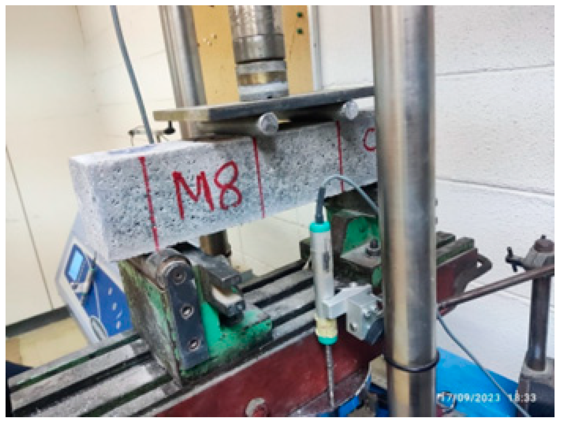
A flexural strength test was conducted on prisms of 75 × 75 × 380 mm3 in accordance with the guidelines outlined in ASTM C1018-97 [26]. A MATEST universal multispeed load frame, capable of applying a maximum force of 50 kN and loading at a rate of 0.5 mm per minute, served as the apparatus. The test was performed after a curing period of 28 days. The flexural strength included the first cracking strength and maximum post-cracking strength, and the load–deflection curve of the specimens was evaluated through the utilization of a typical third-point bending test, as shown in Figure 2.

3. Results

3.1. Flowability

The flowability of the selected mixes was evaluated using a flow table test. The results of the study indicated that an increase in both the volume fraction and aspect ratio of fibers had a negative impact on flowability in all of the mixtures examined. At first, the decrease in flowability was small, but once the volume percentage passed a particular threshold, the deterioration in flowability became more significant. Regarding the aspect ratio, it was observed that the mixes made with carbon fibers exhibited favorable flowability up until an aspect ratio of 3125, corresponding to the mix G2M9. However, it is worth noting that carbon fibers that exceeded this point experienced a notable decline in flowability beyond this point.

3.2. Compressive Strength

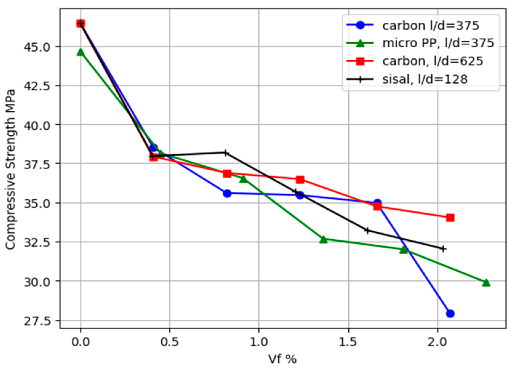
Figure 3 shows how the fiber volume percentages and aspect ratios (l/d) affected the compressive strength of fiber-reinforced cementitious composites (FRCCs). This study found that as the volume percentage of fibers increased, the compressive strength decreased, which was a pattern that was constant across carbon and polypropylene microfibers with l/d = 375. However, while there was a similar pattern of decreasing compressive strength, as seen in mixtures with an l/d ratio of the fibers of 675, there was no precipitous fall in compressive strength when the volume fraction hit 2.06%. This discrepancy emphasized the different impacts of l/d, although increasing the aspect ratio might reduce the compressive strength due to inadequate compaction and flowability difficulties, as occurred for FRCCs with fibers that had an aspect ratio of 375. Higher aspect ratios often result in enhanced tensile strength and a more solid connection; this is the reason for the mixes of FRCCs with an aspect ratio of 625. Critical thresholds were established at 1.6% for carbon fibers and 1.81% for polypropylene fibers with l/d = 375, beyond which the compressive strength decreased by 25% for carbon fibers and by 15% for polypropylene fibers. This reduction was due to the fibers’ lower elastic modulus when compared with plain mortar, which had a major influence on the composites’ total elastic modulus. One study [27] supports these findings by noticing a loss in compressive strength with the presence of lightweight fibers such as polypropylene, with declines of 9.48% and 14.45% after 7 and 28 days, respectively, for combinations containing 4% fibers. At increasing volume fractions, the fibers have a lower modulus of elasticity and less interfacial bonding strength, which accounts for this pattern. It has been shown [28] that adding steel fibers in certain quantities can improve the compressive strength. Their findings showed that short steel fibers at 0.4% and 0.8% volumes can boost strength by 5.84% and 9.98%, respectively, after 28 days, most likely due to the improved tension management between the matrix and fibers, which delays fracture onset.
The influence of Kevlar fiber on the compressive strength of concrete was carefully assessed [29]. The researchers discovered that Kevlar-fiber-reinforced concrete (KFRC) specimens with a 0.5% weight ratio of Kevlar fiber had the maximum compressive strength in both quasi-static and dynamic testing, overcoming those with higher fiber ratios of 1.0% and 1.5%. This suggests that a 0.5% weight ratio of Kevlar fiber is ideal for increasing the compressive strength of concrete under both static and high-strain-rate dynamic loading.
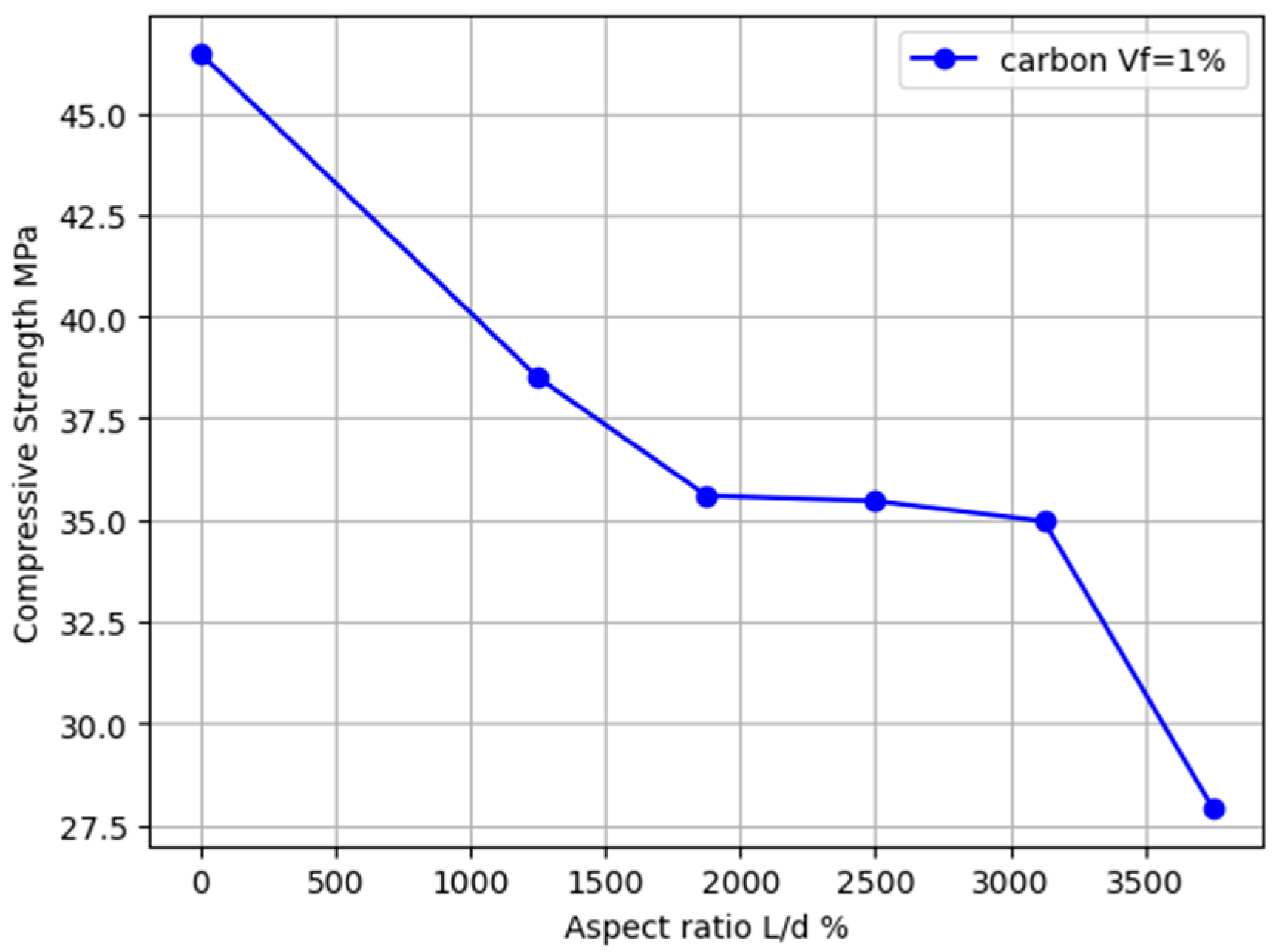
Figure 4 shows how varied aspect ratios of carbon fibers with equal volume fractions impact the compressive strength of fiber-reinforced cementitious composites (FRCCs). This study examined carbon fibers ranging in length from 10 to 30 mm, rising in 5 mm increments, and yielding aspect ratios between 1250 and 3750. The compressive strength was diminished by 30% at an aspect ratio of 3125 and 40% at the maximum aspect ratio of 3750. This decrease comprised a 20% drop due to the inclusion of 1% adjusted fiber content, with an additional 10% and 20% loss as the aspect ratio became 3125 and 3750, respectively. It could be observed that the compressive strength of the composites decreased with the increase in the volume fraction (Vf %) of sisal fibers. At a 2.0% fiber volume fraction, the compressive strength was reduced to about 32.0 MPa. This change represented a decrease in compressive strength of approximately 31.0%.

3.3. Equivalent Elastic Bending Stress versus Deflection

The load resistance is influenced by the dimensions of a specimen and its span. Thus, in order to facilitate comparisons with findings from various scholarly articles, it is more suitable to express the load–deflection curves in terms of the equivalent elastic bending stress versus deflection [30]. The stress can be calculated for any load on the load–deflection curve using the calculation provided in the ASTM C1609/C1609M-12 standard [31] for the third point-loading arrangement as follows:
f = P L / ( b d 2 )
where; (f) is the equivalent elastic bending stress; (P) is the applied load; (b) is the width of the specimen; (h) is the depth of the specimen; (L) is the span between the supports c/c.
Figure 5 shows parts of the prisms and their fracture locations. It is evident that the fractures did not always appear exactly in the center. Several of the cracks were found around the edges of the middle spans, showing that fiber-reinforced concrete (FRC) responded differently from regular concrete. This strength variation could have been connected to areas with densely packed fiber bundles, which may have increased the structural integrity of those sections. As a result, the central line of the span may not have been the weakest point. However, all of the cracks originated within the middle span of the prism.
Figure 6a displays the flexural stress versus deflection curve for carbon-fiber-reinforced mortar samples with fibers of 5 mm in length. Initially, the curve was intended to grow linearly, indicating the material’s elastic behavior, until reaching a peak representing the final flexural strength. The peak flexural stresses measured for the series of G1M1 to G1M5 were 4.61, 5.07, 6.22, 9.26, and 9.59 MPa, respectively. These results exceeded the first crack-formation stress, which was calculated to be 3.8 MPa using the flexural strength of the control samples without fibers. Furthermore, the findings showed that the fiber-reinforced specimens had a larger deflection by approximately two times as a maximum at peak stress, indicating the increased toughness provided by the addition of carbon fibers when compared with the non-fiber-reinforced specimens.
The insertion of fibers with a low elastic modulus into a concrete or mortar matrix reduces the total elastic modulus of the composite material [32]. Following the peak stress, the material’s load-bearing capacity declined significantly, indicating a response subsequent to cracking.
The exhibited stress–deflection curve indicated a primarily brittle failure mode, with material breaking followed by little to no plastic deformation. It is worth noting, however, that the flexural strength increased by two to three times when compared with that of the non-fiber specimens, with only a single fracture appearing prior to reaching the peak load. Following this peak, there was a quick drop in load-bearing capability, with the residual strength varying between 1 and 2.5 MPa depending on the fiber volume percentage in the mixture. Following fracture creation, the specimens maintained structural integrity rather than breaking into two different pieces, as seen in the adjacent figure.
Figure 6b shows the impacts of several carbon fiber lengths within the mortar, ranging from 10 mm to 30 mm and incremented by 5 mm for each mix configuration. Throughout the studies, the fiber concentration was constantly about 1% by volume. This image most likely depicts a succession of curves, each corresponding to a particular fiber length. All of these curves showed a continuous tendency, with flexural stress reaching a peak that far surpassed the flexural strength of the control specimen. By interpolating the values of fiber volume fractions between 0.81% and 1.23%, one could approximate the maximal stress value for a 1% fiber volume fraction, as shown in Figure 6b. This value was slightly greater than the maximum tension detected in specimens reinforced with a 1% volume of fibers at an aspect ratio of 625.
This tendency emphasized the importance of the aspect ratio in determining the composite material’s flexural capabilities, as well as its post-cracking performance. One distinguishing aspect of these curves was the more gradual post-peak decline in bending stress. This was in contrast to the behavior observed in the group with an aspect ratio of 625, which showed a more rapid drop in stress. As the aspect ratio increased to 2500 and higher, the stress decrease along the descending branch became less dramatic, suggesting improved material characteristics.
At an aspect ratio of 3750, an anomaly in which the flexural strength dropped more quickly was discovered, showing higher brittleness in comparison with that of the lower aspect ratios. This increased brittleness was mostly due to a considerable drop in the mix’s flowability and compressive strength produced by the fibers’ excessive length. These lengthy fibers most likely hampered the efficient compaction process during specimen preparation.
Specifically, the specimens with aspect ratios of 2500 and 3125 initially had a quick reduction in load-bearing capacity from peak values of roughly 44% and 28%, respectively, to 4.24 and 5.55 MPa, but this was followed by a more steady fall.
Despite the smooth texture of carbon fibers, the trend of high flexural strength of FRCCs is due to the greater inter-fiber bonding at higher aspect ratios. A higher aspect ratio usually enhances load transmission efficiency between the fiber and the cementitious matrix.
Figure 6c shows the bending stress vs. deflection curve for mortar reinforced with 3 mm carbon fibers. This curve was predicted to follow a pattern similar to that shown in Figure 6a, beginning with a linear section showing elastic behavior and peaking above the first cracking stress or flexural strength observed in the non-fiber specimens. After the peak, the load capacity decreased significantly, decreasing to between 0.5 and 1.5 MPa. Notably, although they had lower peak stress, the specimens with a 2.07% fiber volume percentage showed a steady drop, indicating a more ductile failure style. When we examined these lines, which had a lower length-to-diameter ratio (l/d) than those in Figure 6a at the same fiber volume percentage, we could see that the peak stress was lower. This demonstrated the role of the aspect ratio in increasing the flexural strength of fiber-reinforced cementitious composites (FRCCs).
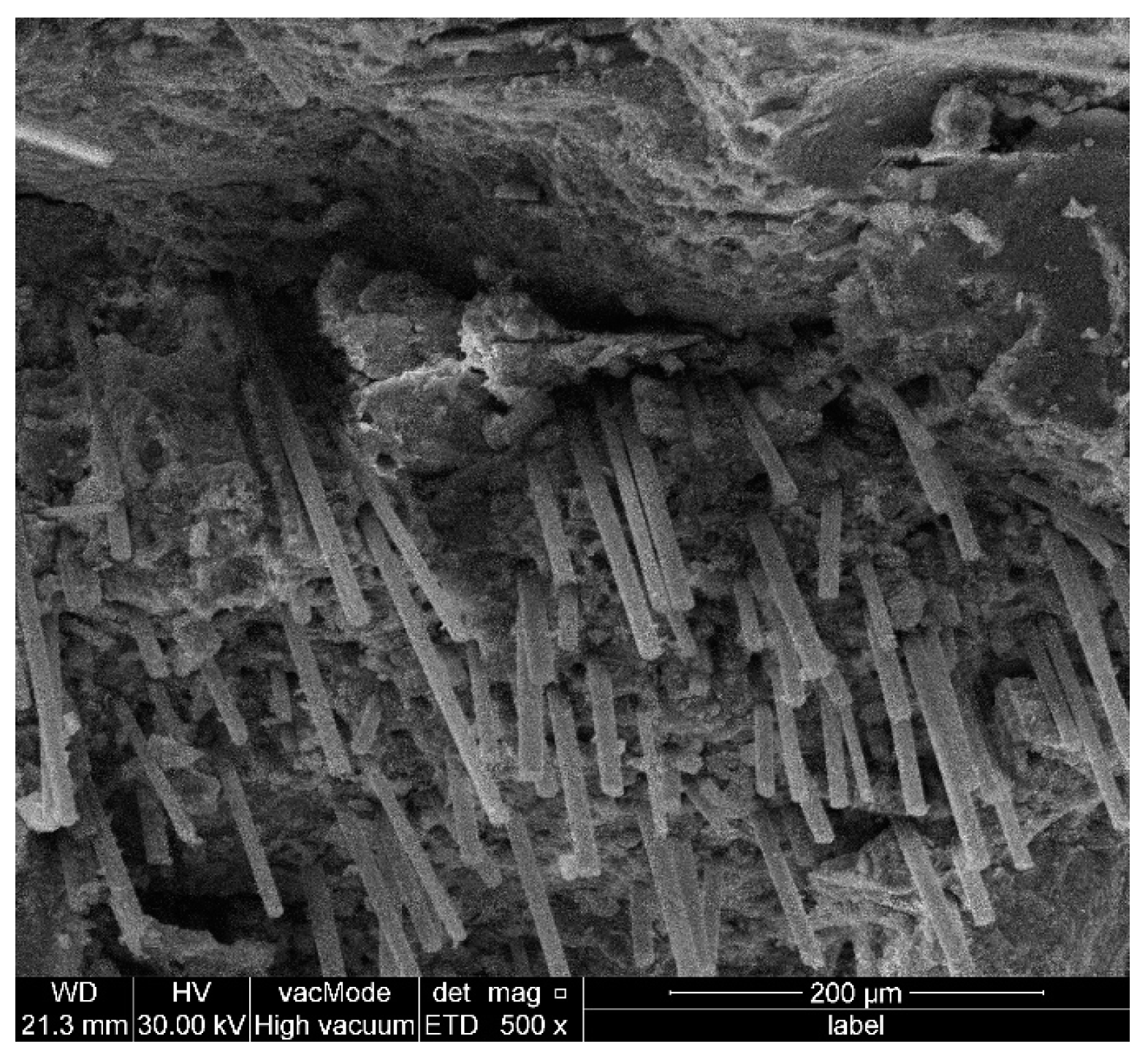
Figure 7 shows SEM images of carbon fibers mixed into a cement-based composite, resulting in short tubular structures with minimal gaps. These fibers have a high aspect ratio and small diameters, resulting in excellent adherence to the cement matrix. Under flexural stress, they increase the composite’s structural integrity. The carbon fibers in the composite help distribute and transmit applied loads across a broader area. This distribution reduces the stress concentration points inside the matrix, allowing the composite to absorb higher loads before failing.
Beyond a maximum flexural load, most of the fibers pull out, causing brittle failure. Despite their outstanding tensile strength, carbon fibers’ smooth surface may result in inadequate energy-dissipation mechanisms during breaking. Consequently, upon surpassing the maximum flexural stress, the weak fiber–matrix link may abruptly and brittlely collapse, causing the fibers to pull out instead of successfully bridging the fissures.
Because of their high aspect ratios, the fibers demonstrated greater inter-fiber bonding prior to reaching maximum flexural stress. These bigger aspect ratios make it easier for the load to be transferred between the fiber and the cementitious matrix. This makes it easier for cracks to be bridged within the matrix. This enhancement boosted the composite’s total strength and deflection at failure [33].
Figure 8a,b provides a detailed evaluation of the effect of polypropylene (PP) fibers on the mechanical response of composite materials. This study focused on the deflection behavior and flexural characteristics at different volume fractions and aspect ratios. The data given in the figures examine the effects of various volume fractions of PP fibers ranging from 0.45% to 2.27%. Figure 8a shows that the micro-PP fibers had an aspect ratio of roughly 375, whereas macro-PP fibers had an aspect ratio of 71. The findings showed a linear connection between deflection and stress up to the limit of proportionality (LOP). The LOP values recorded ranged from 4.37 to 5.17 MPa, with the exception of two mixes (G4M18 and G4M19) that were less than 4 MPa. This observation underscored the material’s early elastic reaction.
Following the limit of proportionality (LOP), there was a significant drop in load, with varying magnitudes depending on the fiber volume percentage. It is worth noting that there was an inverse connection between the fiber content and drop quantity, indicating that increased fiber content increased the material’s ability to withstand cracking and structural failure. In specimens reinforced with micro-fibers, the ratio between the maximum flexural stress (MOR) and the first cracking stress (LOP) was found to be less than one, indicating the presence of deflection-softening behavior. However, when specimens with volume fractions of 1.36% and 1.81% were considered, the aforementioned ratio tended to unity, demonstrating a favorable link between fiber content and improved flexural behavior. Specimens with a volume fraction of 2.27% exhibited distinctive behavioral features. The substantial volume percentage of fibers had a detrimental influence on the mix’s workability, making complete compaction and thorough mixing difficult to achieve. As a result, the percentage decrease in compressive strength was about 33%, emphasizing the need to carefully consider the interactions between fiber content, workability, and strength.
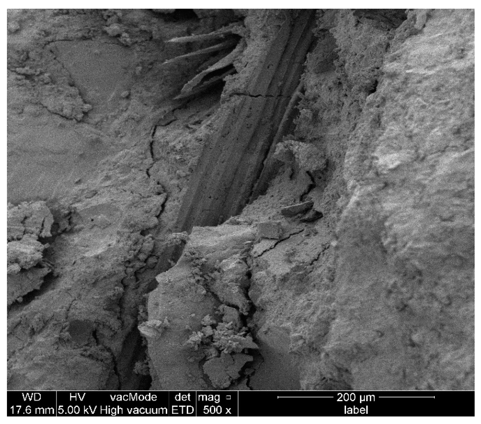
Figure 8b shows the relationship between the equivalent bending stress and deflection for the samples reinforced with macro-polypropylene fibers. The findings showed that deflection hardening occurred equally across these specimens, as the maximal bending stress (MOR) exceeded the limit of proportionality (LOP). This trend was consistent across all samples, with the exception of those with a 0.45% volume percentage of macro-polypropylene fibers. The MOR-to-LOP ratio of 0.66 for these individual specimens was less than 1, indicating a considerable divergence from the overall trend seen. Furthermore, each of these specimens showed significant deflection while maintaining their flexural strength. This separated them from other examples that were strengthened with carbon fibers. Despite having a lower length-to-diameter ratio (l/d), longer macro-polypropylene fibers greatly improved the flexural strength and flexibility of the specimens compared with micro-PP fibers. This discovery emphasized the importance of the volume percentage; the presence of indentations on the surface of macro-polypropylene fibers could enhance the interactions between these fibers and the cement matrix to improve the deflection capacity and post-cracking stress behavior of the composite. The interfacial bond strength is an important aspect of better flexural performance; this highlighted the relevance of fiber qualities other than the aspect ratio in designing fiber-reinforced concrete mixes customized to specific structural needs. Figure 9 displays a scanning electron microscope (SEM) image of a micro-polypropylene (PP)-fiber-reinforced matrix. The image shows several fibers that had completely debonded from their original positions within the matrix. This debonding led to increased deflection under stress. The total percentage of fibers that remained effective in resisting the applied load after cracking decreased, which reduced the overall load-carrying capacity of the material.
Figure 10 shows SEM images of macro-PP-fiber-reinforced cementitious composites, and it is shown that the fibers are partially debonded from the matrix.
Figure 11a,b provide a detailed evaluation of the effect of sisal fibers on the flexural behavior of the cementitious composites. Figure 11a shows how increasing the percentage volume of sisal fibers improved the bending stress obtained by the mortar composite up to the first cracking point; beyond this point, there was a sudden drop in the load, which decreased with an increase in the volume fraction of fibers, particularly when the volume of fibers exceeded 0.81%. Following that decrease, the fibers were able to withstand the imposed stress, and the flexural capacity was gradually raised until it reached the maximum flexural capacity or MOR. The ratio of MOR to the first cracking strength was changed from 0.8 to 1 for specimens reinforced with fiber volumes greater than 0.81%. Following the post-peak load, the load gradually decreased.
Figure 11b shows the effect of sisal fiber (L/d) on the flexural behavior of fiber-reinforced composites with a constant fiber volume percentage (Vf = 1.44%). Up to the point of the initial cracking stress, the behavior of all curves was essentially linear and identical, implying that the composite structure acted consistently regardless of the fiber aspect ratio. After the first cracking stress, each curve showed a significant decrease in stress that was approximately identical across all analyzed aspect ratios, demonstrating a consistent failure process despite changes in fiber length, with minor variances representing the influence of various aspect ratios. The highest flexural stress after cracking was recorded at L/d = 384, indicating an optimal relationship between fiber length and matrix binding at this ratio. For larger aspect ratios, such as L/d = 448 and 512, the curves showed a more notable decrease and poorer stress recovery, highlighting possible concerns such as increased micro-cracking caused by diminished fiber–matrix contact. This was supported by SEM images, as shown in Figure 12, which revealed non-uniform dispersion and gaps leading to micro-cracks.

3.4. Modulus of Rupture

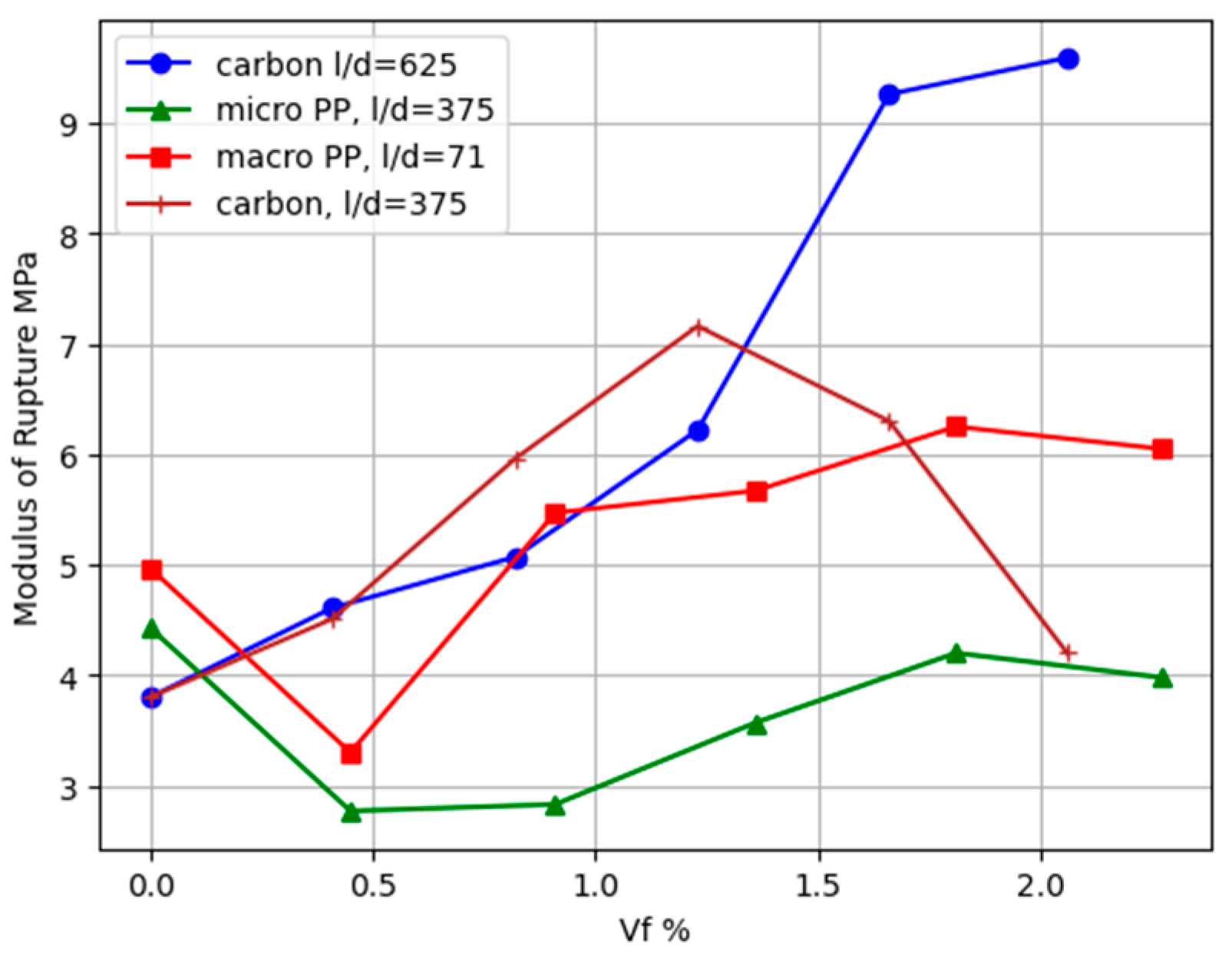
Figure 13 shows how integrating fibers affected the MOR, illustrating how the MOR corresponded with the fiber volume percentage in the mix. For mortars without fibers and a small volume fraction, the MOR was within certain limitations. At first, the inclusion of fibers decreased the MOR (modulus of rupture), suggesting that a small number of fibers did not significantly enhance the ability to bear loads right before failure, as shown in both micro- and macro-polypropylene fibers. However, when the volume percentage of fibers reached a critical threshold, which may be viewed as the minimum volume fraction of fibers, there was an observed increase in the modulus of rupture (MOR). The minimum volume fraction of fibers required to avoid a sudden breakdown may be estimated by calculating the ratio of the tensile strength of the fiber to the tensile strength of the matrix. For prisms reinforced with polypropylene fibers, this value was roughly 0.9%, whereas for prisms reinforced with carbon fibers, it was about 0.1%. Both macro- and micro-polypropylene fibers exhibited a lower modulus of rupture at 0.41%. However, as the volume fraction increased, the modulus of rupture increased for macro-PP fibers, while for micro-PP fibers, it remained lower than the first cracking strength even when the volume fraction reached 0.82%. This difference can be attributed to the lower interfacial bond strength of short and smooth micro-polypropylene fibers compared with long and deformed macro-polypropylene fibers.
However, the addition of carbon fiber, even at a small volume fraction of 0.41%, resulted in a flexural strength that was somewhat higher than the critical threshold. This enhancement signified the participation of the fibers in connecting and bridging the fractures of the prisms, hence enhancing the composite’s capacity to withstand forces following breaking.
Notably, specimens reinforced with carbon fibers had a peak stress that exceeded the flexural strength of the control specimens across all fiber volume fractions. This emphasized the distinct advantages of carbon fibers, such as their higher aspect ratio and tensile strength, over PP fibers in reinforcing mortars.
It was derived by Naaman [34] that the post-cracking strength of fiber-reinforced-cement-based products under direct tension depends on the fiber content, aspect ratio, and interfacial bond strength between fibers and the matrix (τ), as shown in the following equation:
σ P c = Λ . τ . L d   V f
where the coefficient Λ is the result of multiplying numerous factors that determine the effectiveness of the fiber.
The equation accurately predicts the tensile strength after cracking and can be utilized to predict the modulus of rupture for specimens under flexural stress by analyzing the stress distribution across the section of the members. This prediction takes into consideration various characteristics of fibers, such as the fiber content, aspect ratio, and interfacial bond strength between the fiber and matrix.
However, measuring the interfacial bond strength between the fiber and matrix in fiber-reinforced concrete (FRC) is challenging because fiber parameters (e.g., material, texture, shape) have a major influence on bond strength, resulting in inconsistent findings and measurement issues. Furthermore, the stress distribution among cement fibers and the entrance of air spaces during mixing and compaction introduce heterogeneity into bond strength measurements. Despite numerous estimation approaches, the absence of a standard that is agreed upon worldwide for measuring bond strength makes comparisons between studies complicated.
In this study, rather than focusing on the interfacial bond strength between the fiber and matrix, two properties closely related to the bond strength were introduced: fiber tensile strength and matrix compressive strength. This study looked at how various factors affect the flexural strength of fiber-reinforced cementitious composites (FRCCs). The primary variable of interest was the ratio of maximum post-cracking stress to the initial cracking stress, which is called the limit of proportionality (MOR/LOP). This ratio correlated with several independent variables, including the fiber volume percentage (Vf), fiber aspect ratio (L/d), matrix compressive strength (C), and fiber material tensile strength (T). The information gathered was submitted to multi-logistic regression analysis using statistical techniques for predicting nonlinear curves. The overall model structure is shown below:
M O R L O P = b 0 × V f b 1   × ( L d ) b 2   × C b 3 × T b 4
Figure 14 was generated by calculating the ratio of MOR to LOP using the measured flexural strength, as well as the anticipated ratios resulting from this model’s output, for all laboratory specimens and extra data obtained from the literature, which totaled 96 instances. In addition, 33 of the above instances were derived from this study’s experimental work, with the other data points coming from the previous literature [28,33,35,36]. The figure displays a linear connection with the MOR-to-LOP ratio as the dependent variable and V f 0.48 × L / d 0.037 × C 0.161 × T 0.25 as the independent variable; the relation was approximately linear, with a coefficient of determination of R2 = 0.84 and a sum of residual squares of ( O b s P r e d ) 2 = 8.13 ; the slope of the best-fit line was determined to be 0.095.
The prediction equation indicates that fiber characteristics, specifically, the fiber quantity and aspect ratio, have varying effects. Unlike steel fibers, synthetic soft fibers are not rigid, may be folded in a variety of directions, and can be crushed by shear force. As a result, the aspect ratio has far less of an effect than the fiber content.

4. Conclusions

This study looked at the impacts of the content, shape, and type of synthetic nonrigid fibers on the mechanical properties of fiber-reinforced cementitious composites (FRCCs). The key results include the following:
  • Carbon fiber composites have greater flexural strength but poorer ductility than polypropylene. The stress behavior varies greatly depending on the fiber type and aspect ratio, affecting the composite’s mechanical performance.
  • Increasing the fiber volume reduced the compressive strength by 20% for carbon fibers at 1.66% and decreased it by 15% for polypropylene fibers at a volume fraction of 1.81%; beyond this point, the compressive strength decreased notably.
  • Adding additional fibers improved the peak load deflection in composites reinforced with carbon and macro-polypropylene fibers. However, the composites containing micro-polypropylene and natural sisal fibers had nearly the same or lower first cracking load and less deflection in comparison with the fiber-less cementitious matrix, despite the fact that they enhanced the toughness.
  • Carbon fibers with an aspect ratio of 625 increased the modulus of rupture by about three times at a volume fraction of more than 1.66% compared with the cementitious matrix without fibers.
  • Macro-polypropylene at a volume fraction greater than 0.8% contributed to deflection-hardening behavior, which was attributed to the higher interfacial bond strength between fibers, whereas micro-PP fibers with higher aspect ratios tended to display deflection softening following cracking at all volume fractions.
  • According to the results and the model for predicting the ratio of the modulus of rupture to the first cracking strength, the role of the increase in the volume fraction was much greater than the role of the aspect ratio in enhancing the properties of the composite.

Funding

This research received no external funding.

Data Availability Statement

The experimental work conducted as part of this research and the supplementary data obtained from the literature were the sources of all datasets utilized in this study. In total, 96 instances were analyzed, with 33 instances originating from the experimental work in this study, and the remaining data points were sourced from the following references: [27,32,33,34]. The datasets generated and/or analyzed during the current study are available from the corresponding author upon appropriate request.

Acknowledgments

I am deeply appreciative of the invaluable support provided by the Civil Engineering Department staff, particularly those in the Concrete Laboratory and Soil Laboratory, during the preparation and testing of materials.

Conflicts of Interest

The author declares no conflicts of interest.

References

  1. Ravikumar, C.S.; Ramasamy, V.; Thandavamoorthy, T.S. Effect of Fibers In Concrete Composites. Int. J. Appl. Eng. Res. 2015, 10, 419–430. [Google Scholar]
  2. Hao, Y.; Shi, C.; Bi, Z.; Lai, Z.; She, A.; Yao, W. Recent Advances in Properties and Applications of Carbon Fiber-Reinforced Smart Cement-Based Composites. Materials 2023, 16, 2552. [Google Scholar] [CrossRef]
  3. Tabatabaei, Z.S.; Volz, J.S.; Gliha, B.P.; Keener, D.I. Development of Long Carbon Fiber-Reinforced Concrete for Dynamic Strengthening. J. Mater. Civ. Eng. 2013, 25, 1446–1455. [Google Scholar] [CrossRef]
  4. Talikoti, R.; Kandekar, S. Strength and Durability Study of Concrete Structures Using Aramid-Fiber-Reinforced Polymer. Fibers 2019, 7, 11. [Google Scholar] [CrossRef]
  5. Yazıcı, Ş.; İnan, G.; Tabak, V. Effect of aspect ratio and volume fraction of steel fiber on the mechanical properties of SFRC. Constr. Build. Mater. 2015, 21, 1250–1253. [Google Scholar] [CrossRef]
  6. Soufeiani, L.; Raman, S.N.; Jumaat, M.Z.; Bin Alengaram, U.J.; Ghadyani, G.; Mendis, P. Influences of the volume fraction and shape of steel fibers on fiber-reinforced concrete subjected to dynamic loading—A review. Eng. Struct. 2016, 124, 405–417. [Google Scholar] [CrossRef]
  7. Soylu, N.; Bingöl, A.F. Research on effect of the quantity and aspect ratio of steel fibers on compressive and flexural strength of SIFCON. Chall. J. Struct. Mech. 2019, 5, 29. [Google Scholar] [CrossRef]
  8. Liu, T.; Yang, Y.; Chen, Z.; Li, Y.; Bai, R. Optimization of fiber volume fraction to enhance reinforcing efficiency in hybrid fiber reinforced strain hardening cementitious composite. Cem. Concr. Compos. 2020, 113, 103704. [Google Scholar] [CrossRef]
  9. Mashrei, M.A.; Ali, A.S.; Alaa, M.M. Effects of Polypropylene Fibers on Compressive and Flexural Strength of Concrete Material. Int. J. Civ. Eng. Technol. 2018, 9, 2208–2217. [Google Scholar]
  10. Maksum, M.; Alrasyid, H.; Irmawan, M.; Piscesa, B. Effect of steel fiber volume fraction to the tensile splitting strength of concrete cylinder. IOP Conf. Ser. Mater. Sci. Eng. 2020, 930, 012058. [Google Scholar] [CrossRef]
  11. ACI Committee 544. Report on Fiber Reinforced Concrete, ACI 544.1R-96 (Reapproved 2009), American Concrete Institute. 2001. Available online: https://www.studocu.com/pe/document/universidad-peruana-de-ciencias-aplicadas/construccion-i/aci-report-aci-committee-544/54183586 (accessed on 22 August 2024).
  12. Musmar, M. Tensile strength of steel fiber reinforced concrete. Contemp. Eng. Sci. 2013, 6, 225–237. [Google Scholar] [CrossRef]
  13. Banthia, N.; Trottier, J. Test Methods for Fexural Toughness Characterization of Fiber Reinforced Concrete: Some Concerns and a Proposition. Eng. Mater. Sci. 1995, 92, 48–57. [Google Scholar] [CrossRef]
  14. Naaman, A.E.; Reinhardt, H.E. Chapter Characterization of High Performance Fiber Reinforced Cement Composites–HPFRCC, 1st ed.; Naaman, A.E., Reinhardt, H.W., Eds.; CRC Press: London, UK, 1996. [Google Scholar] [CrossRef]
  15. Alrawashdeh, A.; Eren, O. Mechanical and physical characterization of steel fiber reinforced self-compacting concrete: Different aspect ratios and volume fractions of fibers. Results Eng. 2022, 13, 100335. [Google Scholar] [CrossRef]
  16. Yoo, D.-Y.; Yoon, Y.-S. A Review on Structural Behavior, Design, and Application of Ultra-High-Performance Fiber-Reinforced Concrete. Int. J. Concr. Struct. Mater. 2016, 10, 125–142. [Google Scholar] [CrossRef]
  17. Lee, S.K.; Oh, T.; Banthia, N.; Yoo, D.-Y. Optimization of fiber aspect ratio for 90 MPa strain-hardening geopolymer composites (SHGC) with a tensile strain capacity over 7.5%. Cem. Concr. Compos. 2023, 139, 105055. [Google Scholar] [CrossRef]
  18. Lin, C.; Kanstad, T.; Jacobsen, S.; Ji, G. Bonding property between fiber and cementitious matrix: A critical review. Constr. Build. Mater. 2023, 378, 131169. [Google Scholar] [CrossRef]
  19. Amin, A.; Gilbert, R.I. Steel Fiber-Reinforced Concrete Beams-Part II: Strength, Ductility and Design. ACI Struct. J. 2019, 116, 113–123. [Google Scholar] [CrossRef]
  20. Lee, Y.; Kang, S.-T.; Kim, J.-K. Pullout behavior of inclined steel fiber in an ultra-high strength cementitious matrix. Constr. Build. Mater. 2010, 24, 2030–2041. [Google Scholar] [CrossRef]
  21. RILEM TC 162-TDF Test and design methods for steel fibre reinforced concre. Mater. Struct./M 2000, 33, 75–81.
  22. Singh, H. Steel Fiber Reinforced Concrete; Springer: Singapore, 2017; pp. 1–181. [Google Scholar] [CrossRef]
  23. ASTM C128-15; Standard Test Method for Relative Density (Specific Gravity) and Absorption of Fine Aggregate. ASTM Book of Standards. ASTM International: West Conshohocken, PA, USA, 2015; Volume 4.02. [CrossRef]
  24. ASTM C 1437–07; Standard Test Method for Flow of Hydraulic Cement Mortar. ASTM Book of Standards. ASTM International: West Conshohocken, PA, USA, 2007; Volume 4.01.
  25. ASTM C109/C109M-08; Standard Test Method for Compressive Strength of Hydraulic Cement Mortars (Using 2-in. or [50-mm] Cube Specimens). ASTM Book of Standards. ASTM International: West Conshohocken, PA, USA, 2009; Volume 4.01.
  26. ASTM C1018-97; Standard Test Method for Flexural Toughness and First-Crack Strength of Fiber-Reinforced Concrete (Using Beam With Third-Point Loading). ASTM Book of Standards. ASTM International: West Conshohocken, PA, USA, 2017; Volume 4.05.
  27. Abd Elmoaty, A.E.M.; Morsy, A.M.; Harraz, A.B. Effect of Fiber Type and Volume Fraction on Fiber Reinforced Concrete and Engineered Cementitious Composite Mechanical Properties. Buildings 2022, 12, 2108. [Google Scholar] [CrossRef]
  28. Başsürücü, M.; Fenerli, C.; Kina, C.; Akbaş, Ş.D. Effect of Fiber Type, Shape and Volume Fraction on Mechanical and Flexural Properties of Concrete. J. Sustain. Constr. Mater. Technol. 2022, 7, 158–171. [Google Scholar] [CrossRef]
  29. Li, Y.-F.; Huang, Y.-R.; Syu, J.-Y.; Tsai, Y.-K.; Huang, C.-H. A study on mechanical behavior of Kevlar fiber reinforced concrete under static and high-strain rate loading. Int. J. Prot. Struct. 2023, 14, 407–437. [Google Scholar] [CrossRef]
  30. Naaman, A.E. What Do Fibers Do To Concrete: Part I Key Mechanical Properties. In Fiber Reinforced Cement and Concrete Composites; Techno Press 3000: Sarasota, FL, USA, 2018; pp. 89–91. [Google Scholar]
  31. ASTM C1609/C1609M-12; Standard Test Method for Flexural Performance of Fiber-Reinforced Concrete (Using Beam With Third-Point Loading)1. ASTM Book of Standards. ASTM International: West Conshohocken, PA, USA, 2009; Volume 4.05.
  32. Naaman, A.E. High Performance Fiber Reinforced Cement Composites. In High-Performance Construction Materials; World Scientific: Singapore, 2008; pp. 91–153. [Google Scholar] [CrossRef]
  33. Yoo, D.-Y.; Kim, S.; Park, G.-J.; Park, J.-J.; Kim, S.-W. Effects of fiber shape, aspect ratio, and volume fraction on flexural behavior of ultra-high-performance fiber-reinforced cement composites. Compos. Struct. 2017, 174, 375–388. [Google Scholar] [CrossRef]
  34. Naaman, A.E. Modeling Tension. In Fiber Reinforced Cement and Concrete Composites; Techno Press 3000: Sarasota, FL, USA, 2018; pp. 464–472. [Google Scholar]
  35. Ramakrishna, G.; Sundararajan, T. Impact strength of a few natural fiber reinforced cement mortar slabs: A comparative study. Cem. Concr. Compos. 2005, 27, 547–553. [Google Scholar] [CrossRef]
  36. Li, B.; Xu, L.; Shi, Y.; Chi, Y.; Liu, Q.; Li, C. Effects of fiber type, volume fraction and aspect ratio on the flexural and acoustic emission behaviors of steel fiber reinforced concrete. Constr. Build. Mater. 2018, 181, 474–486. [Google Scholar] [CrossRef]
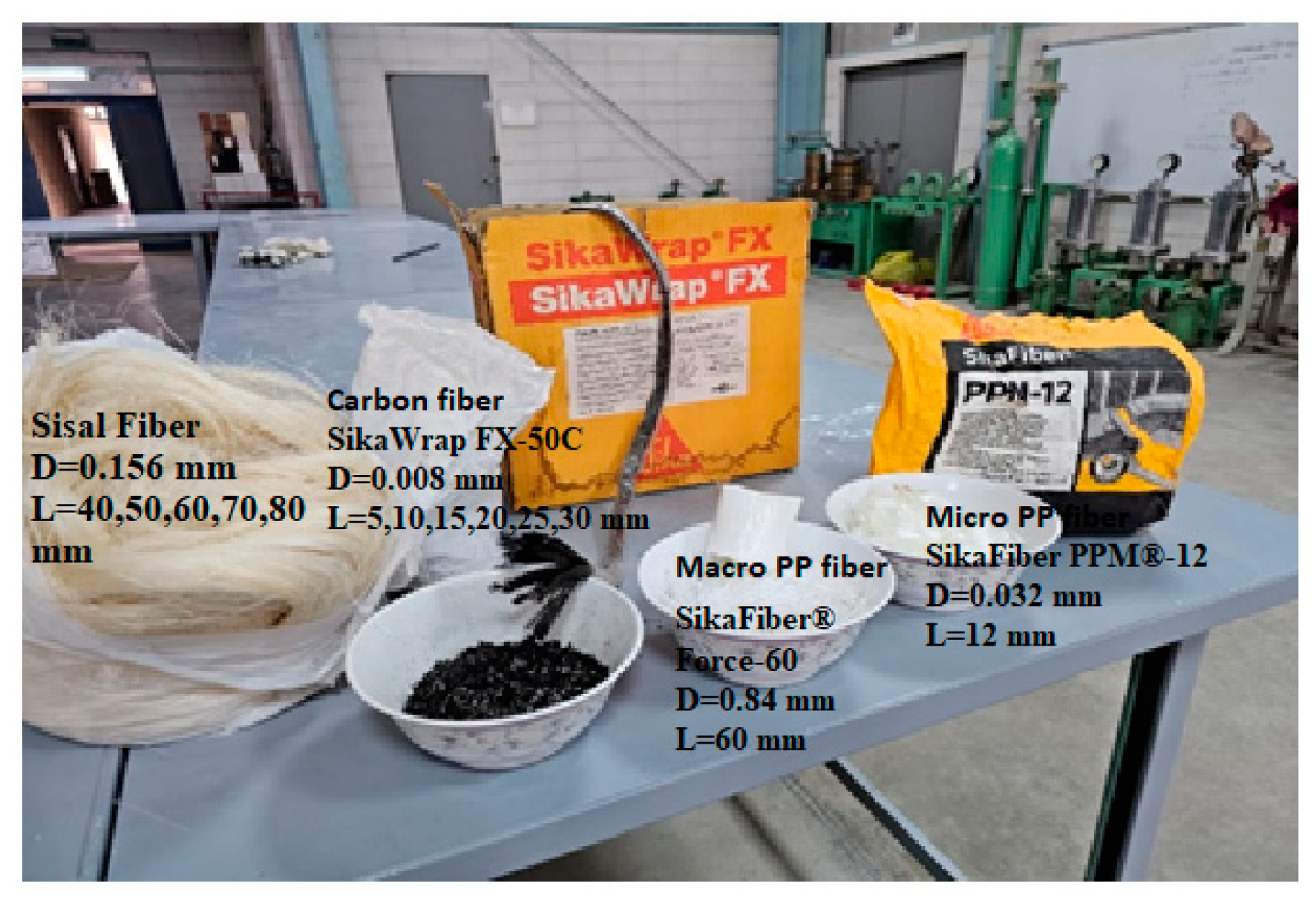
Figure 1. Various types of fibers used for the preparation of specimens.
Jcs 08 00347 g001
Figure 2. Testing setup used for evaluating the flexural strength and behavior of FRCC specimens using a four-point bending test.
Jcs 08 00347 g002
Figure 3. The percentage decrease in the compressive strength of FRCCs versus the volume fraction of different types of fibers at different aspect ratios.
Jcs 08 00347 g003
Figure 4. Percentage decrease in compressive strength of FRCCs versus the aspect ratio of fibers.
Jcs 08 00347 g004
Figure 5. Parts of the prisms showing the modes of failure and crack locations.
Jcs 08 00347 g005
Figure 6. Equivalent elastic bending stress versus deflection of carbon-fiber-reinforced mortar prisms: (a) with different volume fractions of fibers and L/d = 625; (b) with different aspect ratios at Vf = 1%; (c) with different volume fractions of fibers and L/d = 375.
Jcs 08 00347 g006
Figure 7. SEM image of carbon fibers in a mortar matrix. Pull out most of the fibers and matrix failures at the maximum flexural load.
Jcs 08 00347 g007
Figure 8. Equivalent elastic bending stress versus deflection of polypropylene-fiber-reinforced mortar prisms: (a) with different volume fractions of fibers at L/d = 375 (micro-polypropylene); (b) with different volume fractions of fibers at L/d = 71 (macro-polypropylene).
Jcs 08 00347 g008
Figure 9. SEM image of micro-PP fibers in a cement matrix; some of them debonded at the maximum flexural load.
Jcs 08 00347 g009
Figure 10. SEM image of macro-PP fibers in a cement matrix; many fibers were partially debonded from the matrix.
Jcs 08 00347 g010
Figure 11. Equivalent elastic bending stress versus deflection of sisal-fiber-reinforced mortar prisms: (a) with different volume fractions of fibers at L/d = 128; (b) with different aspect ratios of fibers at volume fraction = 1.44%.
Jcs 08 00347 g011
Figure 12. SEM image showing sisal fibers in a cement matrix that are partially debonded due to very small fractures in the matrix and breaking in the fibers.
Jcs 08 00347 g012
Figure 13. Effect of the volume fraction of fibers on the maximum equivalent elastic bending stress (modulus of rupture) of FRCCs reinforced with carbon and polypropylene fibers.
Jcs 08 00347 g013
Figure 14. Regression model fit compared to collected data [28,33,35,36].
Jcs 08 00347 g014
Table 1. Grading and physical properties of the sand.
Sieve Size (mm)% Passing Physical Properties
5 100Bulk specific gravity (SSD): 2.69
2.3699Water absorption: 1.3%
1.1868Moisture content (stock): 1.0%
0.651Fineness modulus: 2.64
0.3015
0.153
Table 2. Chemical composition of fly ash.
OxidesMgO Al2O3SiO2P2O5Sulfur K2O CaO TiO2Fe2O3SrZr
Percent3.96725.07760.1600.2500.2490.5423.570.2035.510.180.151
Table 3. Volume fractions, aspect ratios, and types of fibers used for the preparation of the cementitious mixtures.
Group No.Mix Designationw/bType of FiberVolume Fraction
Vf %
Weight /Batch
(kg/m3)
Aspect Ratio L/d
1G1M00.60None0.00.000
G1M10.60Carbon0.417.47625
G1M20.60Carbon0.8214.94625
G1M30.60Carbon1.2322.41625
G1M40.60Carbon1.6630.29625
G1M50.60Carbon2.0637.59625
2G2M60.60Carbon1.0018.231250
G2M70.60Carbon1.0018.231875
G2M80.60Carbon1.0018.232500
G2M90.60Carbon1.0018.233125
G2M100.60Carbon1.0018.233750
3G3M110.60Carbon0.417.47375
G3M120.60Carbon0.8214.94375
G3M130.60Carbon1.2322.41375
G3M140.60Carbon1.6630.29375
G3M150.60Carbon2.0637.59375
4G4M160.55Plain000
G4M170.55PP (Micro)0.454.09375
G4M180.55PP (Micro)0.918.28375
G4M190.55PP (Micro)1.3612.37375
G4M200.55PP (Micro)1.8116.47375
G4M210.55PP (Micro)2.2720.65375
5G5M220.55Plain000
G5M230.55PP (Macro)0.454.0971
G5M240.55PP (Macro)0.918.2871
G5M250.55PP (Macro)1.3612.3771
G5M260.55PP (Macro)1.8116.4771
G5M270.55PP (Macro)2.2720.6571
6G6M280.60Sisal0.40627128
G6M290.60Sisal0.81153128
G6M300.60Sisal1.20679128
G6M310.60Sisal1.609106128
G6M320.60Sisal2.027133128
7G6M330.60Sisal1.4495256
G6M340.60Sisal1.4495320
G6M350.60Sisal1.4495384
G6M360.60Sisal1.4495448
G6M370.60Sisal1.4495512
Disclaimer/Publisher’s Note: The statements, opinions and data contained in all publications are solely those of the individual author(s) and contributor(s) and not of MDPI and/or the editor(s). MDPI and/or the editor(s) disclaim responsibility for any injury to people or property resulting from any ideas, methods, instructions or products referred to in the content.