Article

Hollow Concrete Block Based on High-Strength Concrete as a Tool for Reducing the Carbon Footprint in Construction

by
Mikhail Elistratkin
1,*,
Alena Salnikova
1,
Nataliya Alfimova
1,
Natalia Kozhukhova
2 and
Elena Pospelova
3
1
Department of Building Materials Science, Products and Structures, Belgorod State Technological University Named after V.G. Shukhov, 46 Kostyukova Str., 308012 Belgorod, Russia
2
Department of Material Science and Material Technology, Belgorod State Technological University Named after V.G. Shukhov, 46 Kostyukova Str., 308012 Belgorod, Russia
3
Department of Standardization and Quality Management, Belgorod State Technological University Named after V.G. Shukhov, 46 Kostyukova Str., 308012 Belgorod, Russia
*
Author to whom correspondence should be addressed.
J. Compos. Sci. 2024, 8(9), 358; https://doi.org/10.3390/jcs8090358
Submission received: 1 August 2024 / Revised: 20 August 2024 / Accepted: 11 September 2024 / Published: 13 September 2024
(This article belongs to the Special Issue Research on Sustainable Cement-Based Composites)

Abstract

:
The production and servicing of cement-based building materials is a source of large amounts of carbon dioxide emissions globally. One of the ways to reduce its negative impact, is to reduce concrete consumption per cubic meter of building structure through the introduction of hollow concrete products. At the same time, to maintain the load-bearing capacity of the building structure, it is necessary to significantly increase the strength of the concrete used. However, an increase in strength should be achieved not by increasing cement consumption, but by increasing the efficiency of its use. This research is focused on the development of technology for the production of thin-walled hollow concrete blocks based on high-strength, self-compacting, dispersed, micro-reinforced, fine-grained concrete. The use of this concrete provides 2–2.5 times higher strength in the amount of Portland cement consumed in comparison with ordinary concrete. The formation of external contours and partitions of thin-walled hollow blocks is ensured through the use of disposable formwork or cores used as void formers obtained by FDM 3D printing. This design solution makes it possible to obtain products based on high-strength concrete with higher structural and thermal insulation properties compared to now existing lightweight concrete-based blocks. Another area of application of this technology could be the production of wall structures of free configuration and cross-section due to their division, at the digital modeling stage, into individual element-blocks, manufactured in a factory environment.

1. Introduction

Reducing CO2 emissions in all production areas has become a global objective necessity in recent decades. Even if the negative impact of this factor on climate change and ecology turns out to be not as significant as it seems now, the struggle for the use of decarbonization methods has already played a positive role and acted as a powerful stimulus for technological development [1,2,3].
A significant number of studies indicate that industries such as construction and the production of building materials are one of the main sources of carbon footprint, ranking third among all industries [4,5,6]. In this regard, research and development aimed at finding ways to reduce CO2 emissions at all stages of the life cycle of construction projects are relevant [6,7,8,9].
As a solution to this problem, a large number of researchers consider an integrated approach to reducing CO2 emissions to be effective, by optimizing all stages of the life cycle of buildings and structures. The authors of [10] offer a roadmap for adjusting concrete production technology. The general idea of the roadmap is to use the following three tools: (1) consume less concrete for new structures; (2) consume less cement in concrete mixtures; (3) consume less clinker in cementing material.
Reducing concrete consumption (Tool (1)), which is the logical pinnacle of this scheme, presents certain difficulties in practice. The most effective method of reducing concrete consumption, increasing the efficiency of cement use, and improving the performance of structures is the use of high-strength concrete instead of traditional ones [11,12,13,14,15]. This is due to the fact that the formation of the structure of high-strength concrete is based on slightly different principles. The main one is to ensure the possibility of self-organization of the relative arrangement of particles in a concrete mass at the submicroscopic level, due to the targeted control of the grain composition and rheology of fresh concrete [16]. With this approach, it has become possible to increase the strength of concrete several times without a significant increase in cement consumption. The positive effect of this approach is achieved by increasing the efficiency of its use and allows the goals of decarbonization methods to be realized.
For example, the authors of [17] carry out a comparative analysis of resource costs and assess the negative impact on the environment of two bridges with similar parameters but built from different types of concrete. The authors conclude that building with high-strength concrete can provide significant reductions in CO2 emissions (up to 50%) for some specific structures. In other cases, where the increase in strength does not lead to a significant reduction in concrete consumption, the reduction in CO2 emissions is achieved by increasing the durability of the structure.
A serious obstacle to the widespread introduction of high-strength concrete is that existing production methods often do not allow the formation of the required rational cross-section of the product, which should become multi-hollow or thin-walled. As an illustration of this idea, the structure of mammalian bones can be referred to as a natural analogue of effective multi-hollow structural elements with a rational structure [18].
The creation of a large number of voids, thin walls and a more complex longitudinal profile creates great technological difficulties. As a rule, this causes the need to simplify the section shape (returning to the traditional T-beam, I-beam, or channel). Due to this, there is again an overconsumption of concrete compared to calculation models, the efficiency of cement use decreases, and, as a result, the level of CO2 emissions increases. Moreover, for many types of concrete products, it is important to save the external configuration, for example, for wall blocks. Taking into account these difficulties, the proportion of structures made from high-strength concrete in the total volume of cement consumption is not large.
In the total volume of concrete production, a significant amount of cement is required for the production of various ordinary building products with low strength, in particular wall blocks, as well as mortars for connecting them together and plastering them. At the same time, the thermal conductivity of wall blocks has a significant impact on the energy efficiency of the building (in CO2 emissions) over the many years of its operation.
A logical step in this direction is to integrate the advantages of high-strength concrete into the large-scale production of building materials for wall construction, such as wall concrete blocks. This will also ensure increased operational efficiency of the wall structures being increased. But, at the moment, no published research results on this issue have been found.
In this regard, the mission of this research was to develop original technological solutions for the production of hollow wall blocks and other high-strength concrete-based products with a complex structure topology.
The proposed approach required solving the following problems:
  • A significant increase in the strength characteristics of the concrete used without excess consumption of cement;
  • Adapting the properties of concrete for the manufacture of hollow blocks with complex configurations with thin walls;
  • Solving the issue of creating the desired external configuration of the block and the structure of its partitions;
  • Solving the issue of connecting products into a wall structure.
Problems 1 and 2 were the subject of a separate study, therefore this article presents only previously obtained results without discussing the process of obtaining them [19,20].

2. Materials and Methods

In accordance with the mission of the study, the research design shown in Figure 1 is proposed.
One of the recognized methods for increasing the efficiency of cement use is the introduction of various mineral additives and increasing its dispersity. The mixture obtained as a result of such actions is called a composite binder. Portland cement CEM II/A-P 42.5N was used to obtain composite binders used for the production of fine-grained concrete. Its mineral composition and some properties are presented in Table 1. A special feature of this cement is the presence of natural opoka in its composition. Opoka is a natural pozzolanic material that is found in many regions and contains, as a rule, 66–85% of reactive silica [21,22,23].
The following components were used as additional ones for the production of composite binders and concretes:
-
Waste from processing heavy concrete with a particle size of 0–1.25 mm (CW).
-
An additive for micro-reinforcement of cement paste (AMRC), which consists of glass fibers shortened to 0.1–0.45 mm with a diameter of 9–13 microns (initial length 12 mm). This additive was produced in laboratory conditions during research.
-
CENTRILIT FUME S is an aqueous suspension of microsilica and Aerosil with an optimal particle-size distribution produced by MC-Bauchemie.
-
The superplasticizing additive “MC-PowerFlow 3100”.
The need to create and use the AMRC additive is associated with the presence of thin partitions in the developed products, which cause the fragility of the hollow concrete blocks. At the same time, the concrete mixture must have high fluidity and penetration capability, which does not allow the use of traditional types of fibers. The proposed reinforcement solution was to reduce the fiber length with the transfer of its effect to the large-scale level of cement paste. This made it possible to partially achieve the main positive effects of a dispersed reinforcement of self-compacting concrete mixtures without compromising their unique properties.
The AMRC additive was obtained by joint mixing and grinding in a ball drum mill of quartz sand and glass fiber with a mass ratio of components of 2:1. Here, sand particles acted as small-sized grinding bodies, transmitting the effect of the main grinding bodies directly to the fibers. Due to this, a decrease in fiber length occurred, depending on the duration of processing. In addition, sand grains were partially crushed and subsequently acted as an additional fine filler in the concrete mixture and prevented the clumping of fiber fibers. Quartz sand was used as a fine aggregate, the granulometry of which is shown in Table 2.
To give the required configuration to the experimental samples, polymer formwork and molds were used. As part of laboratory experiments, the production of disposable formwork and void formers was carried out using the FDM 3D-printing method. PLA material was used as filament. The production process of void formers is shown in Figure 2.
As a criterion for assessing the effectiveness of using Portland cement in concrete (CEUC—criterion of effectiveness of using clinker), the ratio of concrete strength (at 28 days) to the specific proportion of clinker was adopted, i.e., this is the strength value provided by 1% of clinker (CC—clinker component) of the total weight of solid components in concrete (specific strength, MPa per 1% of CC). This criterion allowed us to select the most effective solutions for different strengths. The CEUC criterion or specific strength was calculated using the formula:
CEUC = R28/CC,
where CC is the clinker proportion in concrete to the total weight of its solid components, in wt.%; R28 is the compressive strength of concrete after 28 days, in MPa.

3. Results

3.1. Justification of the Idea

Most wall blocks nowadays manufactured are made from the following two types of lightweight concrete:
-
Cellular concrete;
-
Concrete containing porous aggregates.
The blocks made of cellular concrete are the most consistent with the considered resource-saving criteria. Due to the peculiarities of the technology and structure, they have minimal filling of the section with concrete and are characterized by good thermal performance. However, the technology for manufacturing cellular concrete is quite complex and energy-consuming (grinding of components, autoclave processing), and attempts to improve the ratio of strength and thermal conductivity further aggravate these disadvantages and have a certain physical limit.
The production of wall blocks based on lightweight concrete with porous aggregates, on the contrary, is simple and provides acceptable results, but a further decrease in thermal conductivity without loss of strength is limited by the density and strength of porous aggregates.
In addition, the optimization of the properties of lightweight concrete is always complicated by the presence of a negative feedback between strength and thermal conductivity (or average density), and the efficiency of wall masonry made of concrete blocks is further reduced by the use of cheap but low-effectiveness masonry mortars.
In light of the above, the idea of improving the quality of structural and thermal insulation wall blocks by increasing the proportion occupied by voids in them, while reducing the thickness of the walls and increasing their density, seemed promising, as shown in Figure 3. This could be achieved by manufacturing these wall blocks using high-strength self-compacting concrete mixtures poured into molds containing special non-removable cores that formed the required volume and shape of voids in the final concrete.
The use of polymer void formers of various configurations ensured the formation of the required topology of the block structure and, if necessary, a butt connection system of the “Lego block” type.
This approach made it possible to clearly distribute the structural and thermal insulation functions between structural elements (concrete walls and air voids), which simplified the design and optimization of the block properties.
The use of high-strength concrete of at least strength grade B90–B100 to obtain thin-walled hollow blocks opened up the possibility of reducing the thickness of partitions compared to traditional concrete of strength grade B5–B20. This allowed us to significantly reduce the degree of filling of the section with the most expensive and resource-consuming raw component by reducing the thickness of the walls to 5–10 mm, and the thickness of the internal partitions to 3–5 mm. This also reduced the weight of concrete-based blocks, making them more convenient to use.
An important advantage of the proposed technology is that the use of highly fluid self-compacting concrete mixtures and 3D additive technologies for the production of void formers makes it possible to obtain almost any configuration of the internal space of the final concrete material. This will make it possible to implement in real products structures created by computer modeling methods that minimize thermal and acoustic flows, uniformly distributing internal stresses.

3.2. Composition and Properties of Self-Compacting Concrete

For the manufacture of hollow concrete blocks with thin walls, mixes of self-compacting fine-grained high-strength concrete (1–3), shown in Table 3, were used, and their properties are given in Table 4.
These concrete mixes were developed as part of previous research [19,20]. The main component of self-compacting high-strength concrete was a composite binder with the following component ratio: Portland cement (CEM II/A-P 42.5N)—70%; recycled heavy concrete products of a fraction of 0–1.25 mm (CW)—30%, which is produced by their joint grinding. The specific surface area of the resulting composite binders was 490–530 m2/kg.
The strength of the consolidated composite binder (without the use of sand) was 96.7 MPa at a water/binder ratio of 0.22. The compressive strength of the composite binder, at a cement/sand ratio of 0.305 (ensuring a standard mixture consistency) was 58.3 MPa.
In this study, cement type CEM II/A-P 42.5N with increased sulfate resistance was used, containing about 10% (by wt. %) of natural pozzolana (opoka) (Table 1). This choice was justified by the need to ensure maximum binding of free Ca(OH)2 released during the hardening of the C3S and C2S phases to obtain durable high-strength concrete and increase the efficiency of using the clinker component. The presence of natural pozzolana in cement reduces its cost, clinker component, and makes it possible to reduce, and in some cases, completely avoid the use of microsilica additive, which have a high cost and complicate the technology.
Portland cement CEM I 42.5N was used to produce the ordinary fine-grained concrete as a control (Table 4, Mix 4).
A new solution aimed at increasing the efficiency of using the clinker and reducing the fragility of high-strength concrete was the use of micro-reinforcing additives. The micro-reinforcing additive used in the study was a glass fiber with a fiber length of 12 mm, which was reduced to 0.1–0.45 mm by mechanical processing in a ball mill together with quartz sand. The microstructure of Mix 1 (Table 4), containing a micro-reinforcing additive, is shown in Figure 4.
Fractionated quartz sand, the granulometry of which is presented in Table 2, was used as a fine aggregate in concrete.
The resulting concrete mixtures had a very high fluidity, necessary for the manufacture of blocks with thin walls, and at the same time had a high compressive strength of over 140 MPa. These characteristics explained the absence of filler or fiber particles larger than 0.6–0.8 mm in the mixtures. The microstructure of the resulting concrete, shown in Figure 4, was characterized by a high density and good adhesion of the cement paste to the aggregate and fiber and a fairly uniform distribution of micro-reinforcing fibers.
An important environmental feature of the developed concrete was the high efficiency of using the clinker component (CC proportion) in comparison with traditional fine-grained concrete (Mix 4), expressed by the CEUC parameter (Table 4, columns 12 and 13) of 1.9 MPa. The high-strength concrete used in the study (Mixes 1, 2, 3) had CEUC values above 5.1 MPa/1%, which increased with the introduction of microsilica and micro-reinforcing additives.
Thus, the developed high-strength self-compacting fine-grained concrete had all the characteristics necessary to obtain energy- and resource-saving thin-walled blocks with complex configurations, such as the following:
-
High fluidity and absence of large particles in the mixture;
-
Strength grade over B110;
-
Increased impact strength;
-
Efficiency of cement use 2.5–3 times higher compared to ordinary concrete.

3.3. Creating the External Configuration and Partitions of the Block

Traditional methods of manufacturing wall blocks involve the use of special molds or press molds, which specify the required dimensions and configuration of the final products. They make it possible to produce compact or hollow products with several standard configurations (depending on the forms used) with quite thick walls. The high wall thickness (more than 15–20 mm) is due to the relatively low strength of the concrete used, the presence of large particles of porous aggregate, and the low formability of the mixture. Also, the reason for the formation of thick walls is the need to immediately demold the block when using the vibration compaction method, or for a block that has not reached the stripping strength after 1–2 days, when using plastic mixtures.
To implement the proposed concept of thin-walled or hollow concrete blocks, with maximum use of the advantages of self-compacting high-strength concrete, the focus was on the use of non-removable polymer void formers produced using 3D printing with the FDM method (Figure 2).
In the case when it is necessary to produce blocks (or samples) of standard sizes, using the FDM method, only void formers are produced, which, during molding, are placed in a collapsible metal mold (Figure 5).
In the case where it is required to manufacture a product with a non-standard shape or size, the entire disposable formwork (Figure 6), consisting of external walls and internal partitions, can be printed using the FDM method and a 3D printer.
The process of direct production of concrete blocks using the developed technology is very simple. The prepared high workable concrete mixture is poured into any zones of the future wall of the concrete block through a special tray, as shown in Figure 7a. If possible, to speed up the process, it is advisable to supply the concrete mixture to the zone where several channels intersect or simultaneously pour it into several zones of the future concrete product.
Under gravity, the concrete mixture, like any ordinary liquid, is uniformly distributed, filling the entire available volume. Pouring the mixture through a tray is necessary to remove more air bubbles from the concrete mixture. Otherwise, air bubbles trapped in the lower part of the product, due to the high viscosity of the mixture, do not have time to rise to the top before the concrete begins to set, which deteriorates the quality of the resulting hollow concrete block.
An important advantage of high-strength concrete is the high rate of hardening in the initial period, which is achieved without the use of accelerating additives or heat treatment. Depending on the air temperature in the laboratory, 12 h after molding, the concrete reaches a strength of 20–25 MPa, which is enough to demold block with simple configuration without the risk of damage. If the hollow concrete block has a complex configuration and has thin protruding parts, then demolding (including removal of the outer polymer shell) is recommended after 2–3 days, when the strength is 50–60% of the designed one. This helps reduce the risk of damage to the thinnest parts and front surfaces of the hollow concrete block.
The final stage of solidification of the hollow concrete block can occur either in aero-aquatic conditions or in a water environment, as shown in Figure 7b. The strength of concrete, hardening under the above-mentioned conditions at a temperature of 20 ± 2 °C, after 5 days, was more than 70% of the 28-day value, which would allow the blocks to be immediately sent to the stockroom or to the consumer. Due to low water absorption, up to 3% (Table 4 Column 10), and low content of concrete matrix, hollow blocks do not require a drying procedure even after curing in water. It is enough to remove water from the void formers if they have horizontal partitions or have a bottom.
Thus, the use of high-strength concrete, within the framework of the proposed concept to increase the efficiency of wall concrete blocks, provides an additional reduction in energy consumption and CO2 emissions due to the elimination of the heat treatment of concrete blocks.
Polymer void formers are not removed from the resulting concrete blocks, and during their subsequent service, they help improve the thermal insulation characteristics of the blocks. Due to the presence of a partition system inside the void formers, the total volume of the cavity in the block is divided into separate chambers, which helps reduce the intensity of convection heat transfer. At the same time, there are no significant concerns about the possible migration of volatile substances from the polymer void former into the interior space of the room due to the low porosity and permeability of the high-strength concrete matrix in the block.

3.4. Opportunities, Prospects, and Challenges of the Technology

The small thickness of the walls and partitions of the developed hollow concrete blocks initiates problems of connecting them into a single structure. The basic method seems to be the use of the “Lego-block” connection principle. For this, the studied thin-walled blocks were equipped with a butt connection system, which consisted of concrete X-shaped protrusions at the top of the internal partitions. At the bottom of the blocks, corresponding recesses were made. The production of X-shaped joint elements was carried out by modifying the configuration of polymer void formers (Figure 6), and the concrete blocks were molded upside down. Figure 8 shows options for the linear and angular assembly of several blocks into a fragment of a wall structure. The proposed method ensures easy and precise placement of blocks in the wall structure and their good horizontal shear resistance.
To ensure the possibility of building walls with a more complex configuration, it is necessary to expand the list of elements used, in particular, the following ones:
-
Half blocks—to build door and window openings;
-
Blocks for creating angles of 30 and 45°;
-
Blocks without an upper X-shaped projection for the top row of masonry, including reinforced ones, for supporting floors and other horizontal elements.
To seal and strengthen masonry joints, commercial adhesive compositions suitable for concrete or special ones developed based on organic and mineral components can be used. In some cases, wall blocks can be used without gluing, while forming a reliable structure only due to the butt connection system. For example, this method can be very useful for temporary zoning of space when arranging various events (for example, exhibitions) in large rooms.
The most important advantage of the developed technology is the ability to create wall structures with free configuration: variable cross-section, bending at any angles with any radii, etc. This possibility is achieved by dividing the digital model of a curved linear wall into separate sections—blocks with any configuration. Based on the developed digital models, a special mold is made for each block using the 3D printing method, where a concrete block based on a self-compacting concrete mixture is molded by pouring. The final stage is the assembly of the wall structure from the resulting blocks at the construction site.
Nowadays, the proposed technology for manufacturing walls with a free configuration can only compete with the 3D-printing construction method. This method is extremely promising. However, its classical application cannot ensure the efficiency of cement use, strength, and other performances corresponding to concretes with a quality grade of B100 and higher, which are used in the proposed technology.
Another advantage of the proposed technology compared to the 3D-printing method is the high-quality and durable front surface of concrete blocks, which does not require additional finishing or protection. To further improve the decorative effect of hollow concrete blocks, they can be made of white or volume-colored concrete, and their surface can be textured to resemble traditional wall materials, complemented with decors, monograms, logos, information inscriptions, etc.
The two methods of implementing the technology described above can be successfully combined with each other. For example, non-standard design elements can be added to a structure made from standard Lego blocks to increase its architectural expressiveness, and the internal free-form walls of the building can be made of standard Lego blocks. However, to implement these capabilities, it is necessary to create special software products and additional design work.
One of the most controversial aspects of our technology is the cost and speed of production of polymer void former or disposable molds. The production rate of a void former using a small 3D printer is slow and requires expensive filament with high power consumption. For the industrial implementation of the technology, it is necessary to develop specialized energy-efficient 3D printers with high speed for thermal printing of polymer void formers. Moreover, as a raw material for void formers, various wastes that require recycling should be used, such as polymer bottles and utensils, reused fragments of disposable forms, and other plastic waste. The above issues require appropriate specialized research and unfortunately do not fall within the competence of the authors.
When producing thin-walled blocks with standard dimensions, an alternative solution to the use of the FDM method is the production of non-removable void former from extruded polystyrene foam (XPS) with enough strength and low thermal conductivity. Such void formers can be used in combination with reusable metal molds, as described above.
Another problem that requires attention is the development of a rational configuration of walls and internal partitions in blocks to ensure, with a minimum proportion of concrete in the block, the best combination of structural, heat-insulating, and sound-proofing characteristics.
To assess the potential of the proposed technology, the data presented in Table 5 can be used.
For a comparative assessment, we used data on lightweight concrete-based blocks of the same dimensions obtained in other studies. Block D was made on the basis of large-pore expanded clay concrete [24] with the same average density as blocks A–C, and block E was a cement foam concrete-based block with a lower average density [25]. Since the compositions of all concrete blocks are known, the CC and CEUC parameters were calculated. Based on [26], the CO2 emissions resulting from the manufacture of each block were calculated, including those related to its strength. Based on the data in Table 5, the proposed technology, in comparison with the technology for expanded clay concrete, provided an absolute reduction in CO2 emissions by 10–15%. The relative reduction in carbon dioxide emissions, taking into account the 1.5 times higher strength of samples A–C, was more than 2 times.
In accordance with the data in Table 5, cross-section areas for blocks A–C were similar. At the same time, in block A, the outer walls had the same thickness, but in blocks B and C, the thickness varied. In block B, the weight of the concrete matrix was shifted to the centers of the lateral sides, and in block C, to the corners. A more rational distribution of the concrete matrix made it possible to increase the strength of the blocks, and hence the efficiency of cement use by more than 20% with almost the same consumption of concrete mixture and constant external dimensions of the blocks. At the same time, the manufacturing technology for all blocks was the same, since the main labor intensity took place at the digital modeling stage.
Similarly, by changing the configuration of the walls and partitions of the blocks, their thermal insulation and acoustic properties could be optimized using various modern theoretical and computational models. However, within the framework of this research, the issue of rationalization of sections in blocks was not specifically studied, since it did not fall within the scope of the authors’ competence.
Thus, the proposed technology is a universal tool for the production of concrete products with any configuration and complex rational sections, inaccessible to most existing technologies. Its use is a link in a chain of ways aimed at minimizing CO2 emissions (or carbon footprint) during the production and service of concrete building products.

4. Conclusions

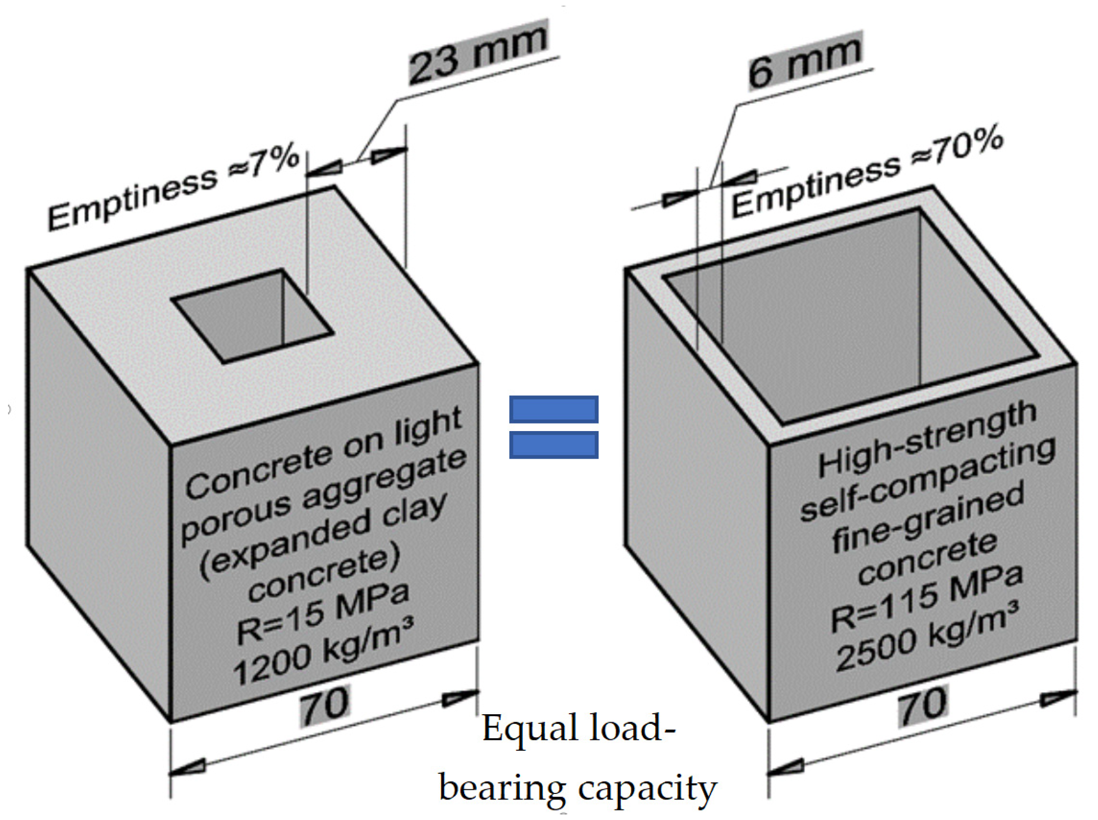
  • Global CO2 emissions can be significantly reduced by increasing the efficiency of production and the use of Portland cement-based building materials. As a new idea, a rejection of the manufacture of wall blocks from structural and thermal insulating lightweight concrete was proposed, in favor of hollow blocks made from high-strength fine-aggregate concrete, produced using the most advanced technical solutions. This made it possible to increase the efficiency of using Portland cement by 2–2.5 times compared to that in ordinary concrete.
  • The maximum reduction in the thickness of walls and partitions and ensuring a rational configuration provided enough strength, minimal conductive and convection heat transfer of the concrete used, with a maximum volume of voids, and low material consumption and weight of the wall block. This approach made it possible to easily rationalize the block cross-section to increase the efficiency of using Portland cement, including by reducing the volume of concrete mixture in the block.
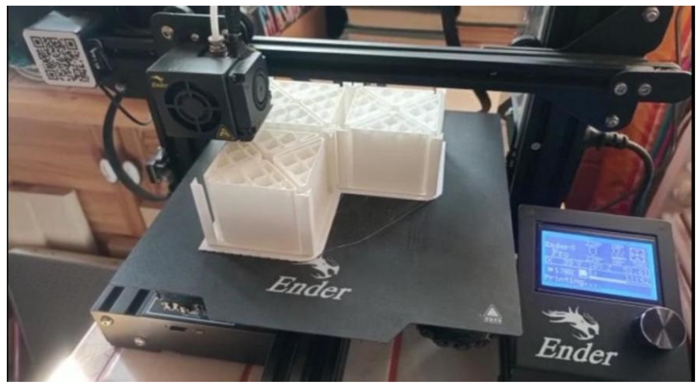
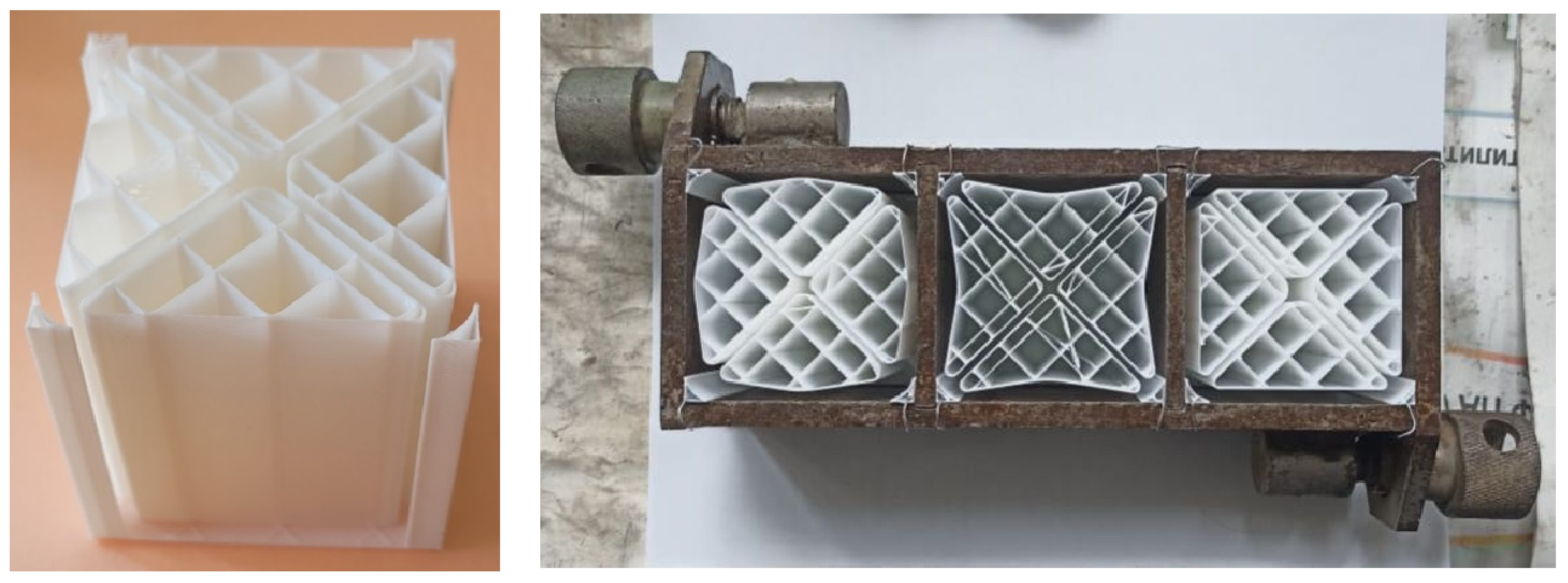
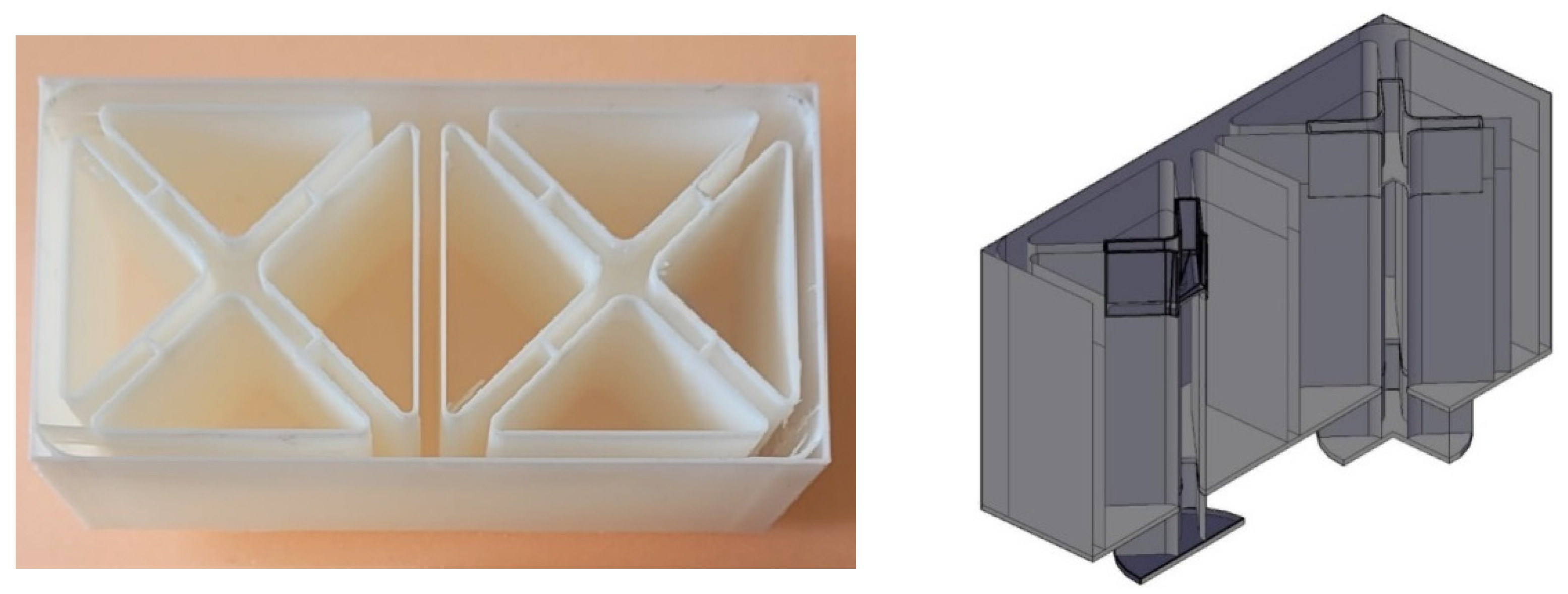
  • The use of the FDM 3D printing method allowed the production of disposable formwork or void formers for the production of hollow concrete blocks with a free configuration of walls and partitions in a horizontal section. Due to this, it became possible to use at each zone of the section the minimum amount of concrete necessary to bear all design loads, taking into account the standardized coefficient of safety. At the same time, varying the configuration of the cross-section in blocks had virtually no effect on their manufacturing technology.
  • The simplicity of wall blocks’ production with a free cross-section configuration allows the developed technology to compete with the 3D printing method in the production of building structures with a free configuration.

Author Contributions

Conceptualization, M.E., A.S., N.A., N.K. and E.P.; methodology, M.E., A.S., N.A., N.K. and E.P.; software, M.E., A.S., N.A., N.K. and E.P.; validation, M.E., A.S., N.A., N.K. and E.P.; formal analysis, M.E., A.S., N.A., N.K. and E.P.; investigation, M.E., A.S., N.A., N.K. and E.P.; resources, M.E., A.S., N.A., N.K. and E.P.; data curation, M.E., A.S., N.A., N.K. and E.P.; writing—original draft preparation, M.E., A.S., N.A., N.K. and E.P.; writing—review and editing, M.E., A.S., N.A., N.K. and E.P.; visualization, M.E., A.S., N.A., N.K. and E.P.; supervision, M.E., A.S., N.A., N.K. and E.P.; project administration, M.E., A.S., N.A., N.K. and E.P.; funding acquisition, M.E., A.S., N.A., N.K. and E.P. All authors have read and agreed to the published version of the manuscript.

Funding

This work was realized in the framework of the Program «Priority 2030» on the base of the Belgorod State Technological University named after V G Shukhov. The work was carried out using equipment of High Technology Center at BSTU named after V. G. Shukhov.

Data Availability Statement

The original contributions presented in the study are included in the article material, further inquiries can be directed to the corresponding author.

Conflicts of Interest

The authors declare no conflicts of interest.

References

  1. Lee, C.-C.; Zhao, Y.-N. Heterogeneity analysis of factors influencing CO2 emissions: The role of human capital, urbanization, and FDI. Renew. Sustain. Energy Rev. 2023, 185, 113644. [Google Scholar] [CrossRef]
  2. Ghazali, A.; Ali, G. Investigation of key contributors of CO2 emissions in extended STIRPAT model for newly industrialized countries: A dynamic common correlated estimator (DCCE) approach. Energy Rep. 2019, 5, 242–252. [Google Scholar] [CrossRef]
  3. Dziejarski, B.; Serafin, J.; Andersson, K.; Krzyżyńska, R. CO2 capture materials: A review of current trends and future challenges. Mater. Today Sustain. 2023, 24, 100483. [Google Scholar] [CrossRef]
  4. Xu, C.; Yang, F.; Zhou, B.; Xu, Y.; Jiang, J.; Chen, X.; Song, M. Total-factor CO2 performance in China’s construction sector: Spatiotemporal trend, driver and future pathway. Environ. Impact Assess. Rev. 2024, 104, 107346. [Google Scholar] [CrossRef]
  5. Chai, S.Y.W.; Ngu, L.H.; How, B.S.; Chin, M.Y.; Abdouka, K.; Adini, M.J.B.A.; Kassim, A.M. Review of CO2 capture in construction-related industry and their utilization. Int. J. Greenh. Gas Control 2022, 119, 103727. [Google Scholar] [CrossRef]
  6. Supriya; Chaudhury, R.; Sharma, U.; Thapliyal, P.C.; Singh, L.P. Low-CO2 emission strategies to achieve net zero target in cement sector. J. Clean. Prod. 2023, 417, 137466. [Google Scholar] [CrossRef]
  7. Ropo, M.; Mustonen, H.; Knuutila, M.; Luoranen, M.; Kosonen, A. Considering embodied CO2 emissions and carbon compensation cost in life cycle cost optimization of carbon-neutral building energy systems. Environ. Impact Assess. Rev. 2023, 101, 107100. [Google Scholar] [CrossRef]
  8. Farahzadi, L.; Kioumarsi, M. Application of machine learning initiatives and intelligent perspectives for CO2 emissions reduction in construction. J. Clean. Prod. 2023, 384, 135504. [Google Scholar] [CrossRef]
  9. Mishina, Y.; Sasaki, Y.; Yokoyama, K. Study on Worldwide Embodied Impacts of Construction: Analysis of WIOD Release 2016. Energies 2021, 14, 3172. [Google Scholar] [CrossRef]
  10. Mehta, P.K.; Meryman, H. Tools for Reducing Carbon Emissions Due to Cement Consumption. Structure 2009, 1, 11–15. [Google Scholar]
  11. Yoo, D.-Y.; Banthia, N. Mechanical properties of ultra-high-performance fiber-reinforced concrete: A review. Cem. Concr. Compos. 2016, 73, 267–280. [Google Scholar] [CrossRef]
  12. Gu, C.; Ye, G.; Sun, W. Ultrahigh performance concrete-properties, applications and perspectives. Sci. China Technol. Sci. 2015, 58, 587–599. [Google Scholar] [CrossRef]
  13. Zhang, X.; Wu, Z.; Xie, J.; Hu, X.; Shi, C. Trends toward lower-carbon ultra-high performance concrete (UHPC)—A review. Constr. Build. Mater. 2024, 420, 135602. [Google Scholar] [CrossRef]
  14. Ji, C.; Wu, Y.; Zhao, Z.; Chen, C.; Yao, L. Life Cycle Assessment of Off-Site Construction Using Ultra-High-Performance Concrete. Sustainability 2022, 14, 6907. [Google Scholar] [CrossRef]
  15. Wang, D.; Shi, C.; Wu, Z.; Xiao, J.; Huang, Z.; Fang, Z. A review on ultra high performance concrete: Part II. Hydration, microstructure and properties. Constr. Build. Mater. 2015, 96, 368–377. [Google Scholar] [CrossRef]
  16. Bonneau, O.; Vernet, C.; Moranville, M.; Aïtcin, P.-C. Characterization of the granular packing and percolation threshold of reactive powder concrete. Cem. Concr. Res. 2000, 30, 1861–1867. [Google Scholar] [CrossRef]
  17. Habert, G.; Arribe, D.; Dehove, T.; Espinasse, L.; Roy, R.L. Reducing environmental impact by increasing the strength of concrete: Quantification of the improvement to concrete bridges. J. Clean. Prod. 2012, 35, 250–262. [Google Scholar] [CrossRef]
  18. Bulygina, I.; Senatov, F.; Choudhary, R.; Kolesnikov, E.; Kaloshkin, S.; Scholz, R.; Knyazeva, M.; Walther, F.; Anisimova, N.; Kiselevskiy, M. Biomimetic scaffold fabricated with a mammalian trabecular bone template. Polym. Degrad. Stab. 2020, 172, 109076. [Google Scholar] [CrossRef]
  19. Lesovik, V.S.; Elistratkin, M.Y.; Sal’nikova, A.S. High strength concrete for lego-blocks. Bull. BSTU Named V.G. Shukhov 2021, 5, 8–18. [Google Scholar] [CrossRef]
  20. Lesovik, V.S.; Elistratkin, M.Y.; Salnikova, A.S.; Pospelova, E.A. Analysis of the Factors of Increasing the Efficiency of Employment Binder in High-Strength Self-Compacting Concretes. Lect. Notes Civ. Eng. 2021, 160, 237–243. [Google Scholar] [CrossRef]
  21. McCarthy, M.J.; Dyer, T.D. Pozzolanas and Pozzolanic Materials. In Lea’s Chemistry of Cement and Concrete, 5th ed.; Butterworth-Heinemann: Oxford, UK, 2019; Volume 9, pp. 363–467. [Google Scholar] [CrossRef]
  22. Liu, Y.; Jia, H.; Sun, Z.; Pan, Y.; Zhang, G.; Zheng, S. High-efficiency removal of gaseous HCHO by amine functionalized natural opoka. Chem. Phys. Lett. 2019, 722, 32–38. [Google Scholar] [CrossRef]
  23. Strokova, V.; Zhernovsky, I.; Ogurtsova, Y.; Maksakov, A.; Kozhukhova, M.; Sobolev, K. Artificial aggregates based on granulated reactive silica powders. Adv. Powder Technol. 2014, 25, 1076–1081. [Google Scholar] [CrossRef]
  24. Sheremet, A.A.; Elistratkin, M.Y.; Sheremet, E.O.; Lesovik, V.S.; Shatalova, S.V. Investigation of physico-mechanical properties of coarse-pored expanded clay concrete for three-layer 3d additive construction. Bull. BSTU Named V.G. Shukhov 2022, 11, 30–39. [Google Scholar] [CrossRef]
  25. Shatalova, S.V.; Chernysheva, N.V.; Lesovik, V.S.; Elistratkin, M.Y.; Sheremet, A.A. Development of a comprehensive solution for 3d printing of wall structures. Bull. BSTU Named V.G. Shukhov 2022, 10, 8–19. [Google Scholar] [CrossRef]
  26. Wu, Q.; Xue, Q.; Yu, Z. Research status of super sulfate cement. J. Clean. Prod. 2021, 294, 126228. [Google Scholar] [CrossRef]
Figure 1. Research design.
Jcs 08 00358 g001
Figure 2. Production of void formers using a 3D printer.
Jcs 08 00358 g002
Figure 3. Visualization of reducing the material consumption of concrete products due to the use of high-strength concrete.
Jcs 08 00358 g003
Figure 4. Structure of high-strength fine-grained concrete with a micro-reinforcing additive.
Jcs 08 00358 g004
Figure 5. Polymer void former and metal cube mold 70 × 70 × 70 mm with installed void formers prepared for molding.
Jcs 08 00358 g005
Figure 6. Disposable polymer mold for producing blocks of free configuration.
Jcs 08 00358 g006
Figure 7. Molding and subsequent consolidation of hollow concrete blocks: (a)—pouring concrete mixture into the mold; (b)—hardening of samples in water; (c)—hardened samples ready for testing.
Jcs 08 00358 g007
Figure 8. Hollow concrete blocks connected with a “Lego block-type” principle: (a)—products with a connection system based on the “Lego block-type” principle; (b)—assembling blocks into a linear structure; (c)—assembling blocks into an angular structure.
Jcs 08 00358 g008
Table 1. Mineral composition and properties of Portland cement CEM II/A-P 42.5N.
Mineral Composition, %Mineral AdditiveSpecific
Surface
(m2/kg)
Setting Time (min)Compressive Strength at 28 Day, MPa
C3SC2SC3AC4AFContent, %TypeInitialFinal
62.2516.444.2513.139.5Opoka34012028054.7
Table 2. Granulometry of quartz sand.
Sieve Opening, mm0.160.3150.63Fineness Modulus
Partial residue,%4145141.4
Total residue, wt. %1005914
Table 3. Mixes of self-compacting fine-grained high-strength concrete.
Mix IDMix CompositionWater/Binder RatioBinder: Quartz Sand
Binder IDSuperplasticizing Additive, %AMRC %Microsilica, %
1Composite binder *1.5200.221:1
2105
3
ControlCEM I 42.5N100.451:3
* Composite binder composition: CEM II/A-P 42.5N–70%; CW—30%.
Table 4. Properties of self-compacting fine-grained high-strength concrete.
Mix IDParameters of Fresh ConcreteParameters of Consolidated ConcreteParameters of the Efficiency of Using Portland Cement
Workability GradeCone Flow Diameter (According to Abrams Cone), cmViscosity GradeAverage Density, kg/m3Compressive Strength (28 Days), MPaStrength GradeImpact Strength, J/cm3Shrinkage, mm/mWater Absorbance, %Freeze–Thaw Resistance Grade, FCC Proportion,
%
CEUC,
MPa per 1% CC
12345678910111213
1PK268V22400145B1100.170.082.9>10025.35.7
2PK267V22455160B1200.170.072.1>10026.95.9
3PK270V22463162B1250.150.093.0>10031.75.1
4not applicable208543B300.110.4410.610022.51.9
Table 5. Characteristics of hollow concrete blocks with different configurations of void formers.
Void Former IDVoid Former ConfigurationCross-Section Area, mm2Weight,
g
Voids’ Proportion in Hollow Wall Concrete Blocks, %Average Density, kg/m3Compressive Strength of Hollow Concrete Block, MPaCC, %CEUC, MPa/1%CO2 Emission, g:
per Block 7 × 7 × 7 cm,
per 1 MPa
Hollow Concrete BlockConcrete Matrix5
Days
28
Days
AJcs 08 00358 i00114782877085824749.813.114.80.8932.5
2.5
BJcs 08 00358 i002147828870840248410.914.60.9932.6
2.2
CJcs 08 00358 i003147028070816250612.316.41.1131.7
1.9
DJcs 08 00358 i004490028765–67820-5.89.2170.5437.3
4.1
EJcs 08 00358 i005490018982550-0.721.9670.0396.9
51
Disclaimer/Publisher’s Note: The statements, opinions and data contained in all publications are solely those of the individual author(s) and contributor(s) and not of MDPI and/or the editor(s). MDPI and/or the editor(s) disclaim responsibility for any injury to people or property resulting from any ideas, methods, instructions or products referred to in the content.

