Article

A New Approach to Designing Multi-Element Planar Solar Concentrators: Geometry Optimization for High Angular Selectivity and Efficient Solar Energy Collection

P.N. Lebedev Physical Institute of the Russian Academy of Sciences, 119991 Moscow, Russia
*
Author to whom correspondence should be addressed.
Optics 2025, 6(1), 6; https://doi.org/10.3390/opt6010006
Submission received: 25 December 2024 / Revised: 28 January 2025 / Accepted: 18 February 2025 / Published: 19 February 2025

Abstract

:
This paper introduces a novel approach to the design of multi-element planar solar concentrators, aimed at optimizing solar energy harvesting systems. The proposed methodology is based on the integration of identical unit cells, strategically arranged to enhance solar radiation capture efficiency and achieve high angular selectivity. Mathematical modeling of the operational principles of the unit cells forms the foundation for determining production parameters and streamlining the concentrator assembly process. Particular emphasis is placed on analyzing key performance metrics, such as solar radiation concentration and optical efficiency, thereby advancing the understanding of the relationship between design parameters and energy output. The study employs MATLAB R2022b and ZemaxOpticStudio 13 software to model the solar concentrator, identifying the optimal cell configuration to achieve a geometric concentration ratio of 3.45, with angular selectivity ranging from 23° to 90°. This research contributes significantly to the field of solar concentrator technology, offering a pathway for more efficient utilization of renewable energy sources and improved adaptability to diverse operating conditions.

1. Introduction

Solar radiation, as the most abundant and widely available natural energy source, possesses the potential to meet global electricity demand. However, the relatively low energy density of solar radiation reaching the Earth’s surface necessitates the use of extensive areas of photovoltaic (PV) converters for efficient energy conversion. These converters are typically composed of silicon wafers with specific electronic structures, such as p-n junctions, heterojunctions, etc. [1]. Unfortunately, the substantial quantities of semiconductor materials required, coupled with the associated manufacturing processes, pose significant limitations to the widespread adoption of solar panels. Consequently, a promising approach to enhancing the deployment of photovoltaic technologies lies in reducing the area of photosensitive elements. This can be achieved by increasing the energy density of incident solar radiation through the use of solar concentration techniques [2].
Solar concentrators are highly efficient devices that convert low-density solar energy into a concentrated radiation flux. Currently, a wide variety of solar concentrator configurations exist, predominantly based on traditional optical systems such as lenticular [3], mirror [4], and planar (Fresnel) optics [5,6]. Table 1 presents the primary types of basic elements used in solar concentrators, their operational mechanisms, and typical values of key characteristics, including the geometric concentration ratio (GCR) and acceptance angle (AA).
The first four rows of Table 1 describe basic elements based on reflective surfaces. These elements exhibit high reflection and are achromatic across the entire solar radiation spectrum, making them suitable as primary components in multicomponent systems. However, their complex manufacturing processes and susceptibility to contamination in outdoor environments significantly reduce their operational efficiency. The subsequent rows of Table 1 summarize volumetric elements that operate on the principles of refraction and total internal reflection. With the exception of Fresnel lenses, achieving high GCRs with these elements often requires a substantial amount of optical material, which increases the mass and dimensions of the concentrator. Consequently, such elements are typically employed as secondary components in more complex multicomponent systems [7]. It is important to note that concentrator configurations are not limited to the shapes listed in Table 1; they can be significantly more complex, combining multiple simple shapes [8] or utilizing materials with varying refractive indices [9].
For solar concentrators to be viable in photovoltaic applications, they must be compact and fabricated from cost-effective materials, such as PMMA or PC plastics [10,11]. Unlike traditional silicon photovoltaic panels, which pose disposal challenges at the end of their lifecycle, plastics can be efficiently recycled or reprocessed for further use. This advantage has led to the limited adoption of concentrators based on lenticular systems or metal parabolic mirrors [12], which are often bulky and prone to issues such as high wind resistance, dust accumulation, and snow buildup. Planar solar concentrators, on the other hand, offer a compact and thin design, avoiding these drawbacks [5]. However, systems like Fresnel lenses [13] are constrained by their aperture size, limiting their ability to collect energy from large areas. Additionally, at larger apertures, Fresnel lenses exhibit a significant back segment, increasing the overall thickness of the system. Their narrow acceptance angle further limits their practical application. Figure 1 provides schematic illustrations of these elements for clarity.
An optimal approach to designing compact solar concentrators involves planar schemes based on optical waveguide principles [38]. Despite their compactness, these systems face challenges in efficiently coupling radiation into the planar waveguide. Current methods for radiation injection include: (i) reflective and refractive elements, which complicate the system; (ii) luminescent materials, which drastically reduce efficiency; and (iii) diffraction gratings, which exhibit strong spectral selectivity. These limitations highlight the need for alternative solutions in the development of planar solar concentrators.
In this paper, we propose a novel approach to the design of multi-element planar solar concentrators with variable geometry and high AA to the angle of incident solar radiation. By combining identical, easily manufacturable elementary cells and arranging them in a specific configuration, we achieve efficient solar energy collection. The number of elementary cells can be adjusted to tailor the radiation concentration area to specific requirements. The study begins with a mathematical analysis of a single unit cell to determine optimal manufacturing parameters, followed by the assembly of a solar concentrator from these cells. Key parameters such as GCR, optical efficiency, and AA are analyzed and presented, providing a comprehensive understanding of the proposed concentrator’s performance. This work contributes to advancing solar concentrator technology, offering a pathway for more efficient and adaptable renewable energy systems.

2. Theoretical Model of Unit Cells

A planar solar concentrator designed for operation in a medium with a refractive index of n 0 λ = 1 consists of an array of identical plane-parallel plates. These plates feature mutually parallel inclined surfaces oriented at an angle β relative to the normal of their receiving surfaces. Each plate has a thickness d and a length l 0 , as illustrated in Figure 2.
The operational principle of a solar concentrator unit cell can be described through the following three key steps:
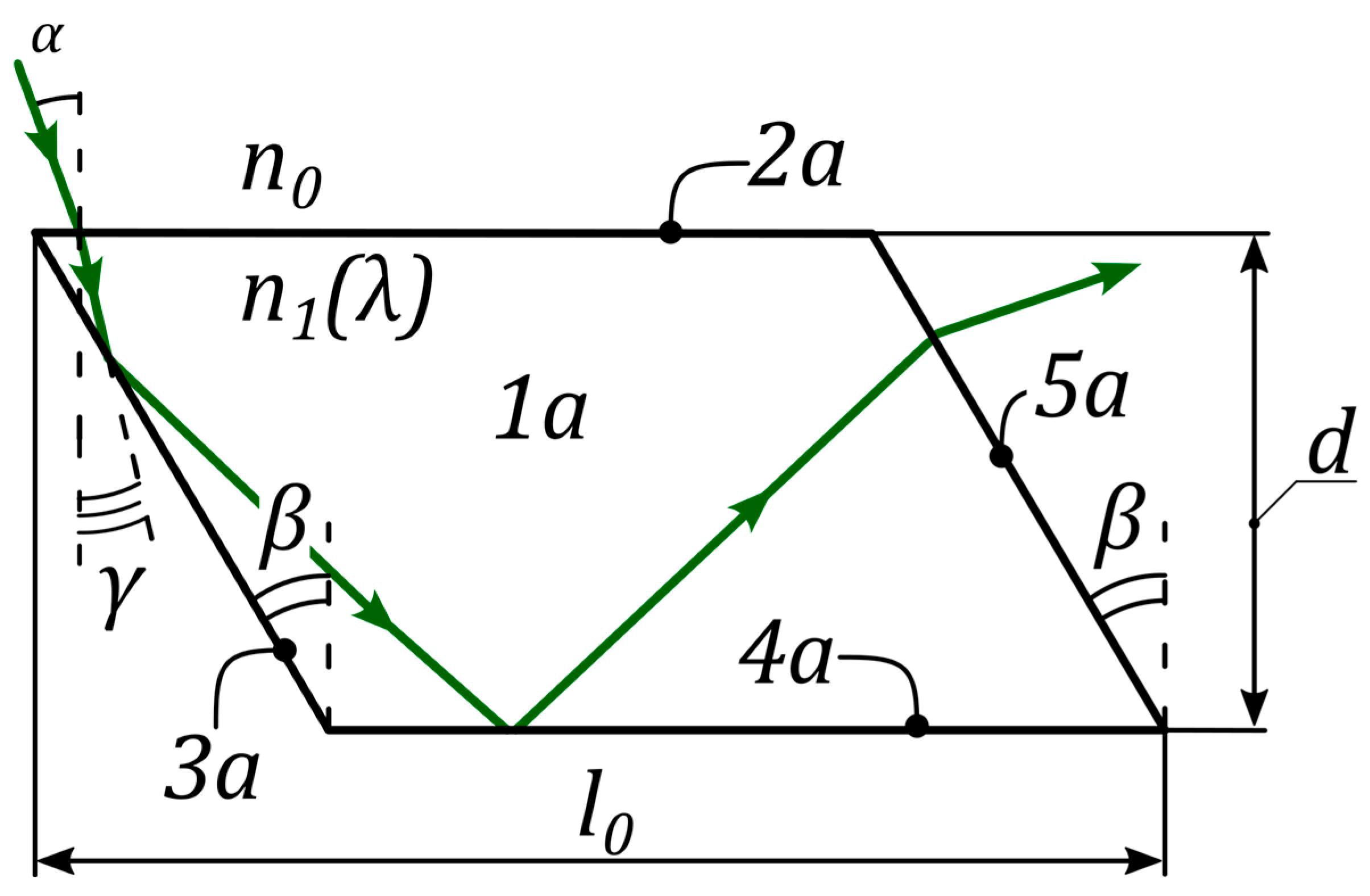
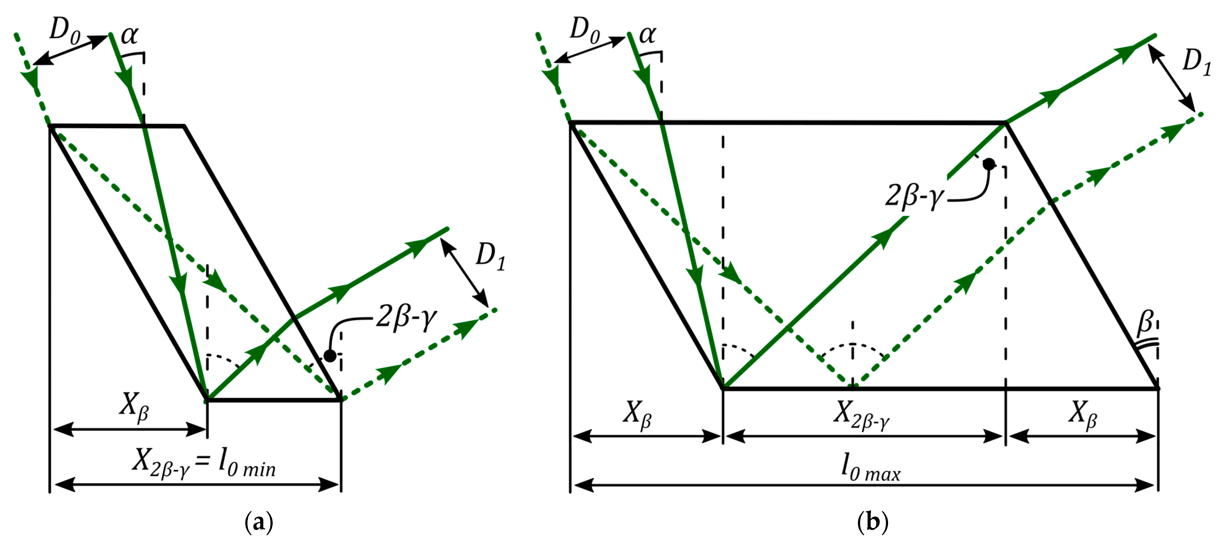
  • Refraction at the Receiving Surface: Electromagnetic waves emitted by the Sun strike the receiving surface (2a) of the plates (1a) at an angle α . Upon entering the material, the waves are refracted according to Snell’s law due to the difference in refractive indices between the external medium n 0 λ and the material of the concentrator cell n 1 ( λ ) , where n 1 ( λ ) represents the refractive index of the cell material.
  • Propagation and First Reflection: As illustrated in Figure 2, the refracted electromagnetic wave propagates at an angle γ toward the nearest end surface (3a) of the corresponding plate (1a). At this surface, the wave undergoes TIR, adhering to the principles of geometric optics.
  • Subsequent Reflections and Propagation: Following the first reflection, the electromagnetic wave travels along the plate (1a) toward the surface (4a), where it is again reflected via TIR. This reflection directs the wave toward the opposite end surface (5a), ensuring its continued propagation within the cell.
For the solar concentrator to function effectively, it is essential to achieve the confinement of solar radiation within the cell through TIR at both the left and bottom faces. The critical parameter governing the fulfillment of these conditions is the angle of radiation propagation γ inside the cell, which is determined by Snell’s law:
γ = arcsin ( n 0 ( λ ) n 1 ( λ ) sin α ) ,
where α is the angle of incidence of radiation on the front face of the cell, and γ is the angle of propagation inside the cell. This angle is pivotal, as it dictates whether the conditions for TIR are met, ensuring efficient radiation propagation within the concentrator.
To optimize the design parameters of the planar solar concentrator, mathematical modeling was conducted using MATLAB software. Figure 3 provides a graphical representation of the relationship between the propagation angle γ , the refractive index of the cell material n 1 , and the angle of incidence α . This relationship is critical, as it directly influences the fulfillment of TIR conditions, which are essential for the effective operation of the concentrator cell.
Next, we derive the angle of inclination β of the side surfaces as a function of the angle of incidence α and the refractive index n 1 λ of the cell material. For the ray incident on the left side face to undergo TIR, the angle γ must satisfy two conditions: (i) γ must be less than the prism angle β , as otherwise the ray will not reach the left face, and (ii) the angle of incidence on the left face must exceed the critical angle for TIR. These conditions yield the first set of constraints:
90 β + γ arcsin ( n 0 ( λ ) n 1 ( λ ) ) β γ .
The second condition for ray propagation within the cell requires TIR to occur at the bottom edge. This imposes the following double inequality on the angles:
arcsin   n 0 ( λ ) n 1 ( λ )     2 β + γ   90 .
Finally, to ensure that the radiation exits the unit cell without undergoing TIR at the right (exit) face, the following constraints must be satisfied:
3 β γ 90 arcsin ( n 0 ( λ ) n 1 ( λ ) ) β 90 2 β + γ .
Combining these conditions, the permissible range for the angle β is determined by the final relation:
β   90 + γ + α e x   3 β γ ,
where α e x = arcsin ( n 0 ( λ ) n 1 ( λ ) ) . The solution region for these constraints is illustrated in Figure 4, where the abscissa represents the angle β (inclination of the side faces), and the ordinate represents the angle α (angle of incidence on the input face). The intensity map highlights the solution regions for different ranges of the cell’s refractive index n 1 ( λ ) .
Analysis of the obtained solution region reveals that an inclination angle of the side face β = 43 ° enables the solar concentrator cell to operate effectively across the entire range of incident radiation angles, 0 < α < 90 ° . This condition, however, is only satisfied when the cell is fabricated from a material with a refractive index n 1 λ within the range of 1.47 to 1.61.
Subsequently, based on the selected parameters, the GCR was calculated for a single solar concentrator cell with side faces inclined at β = 43 ° , independent of the intrinsic length-to-thickness ratio of the cell. The ray-tracing diagram required for this calculation is illustrated in Figure 5. The GCR is defined as the ratio of the maximum beam diameter D 0 incident on the entrance face of the cell to the beam diameter D 1 propagating within the cell.
The aperture of the beam incident on the element, which, after refraction, fully illuminates the side face, is denoted as D 0 . Since the beam strikes the receiving face at an angle α , the relationship between D 0 and its projection x 0 on the input face is given by
D 0 = x 0 cos α ,
where x 0 represents the projection of D 0 onto the input face. The projection x 0 can be expressed as follows:
x 0 = X β X γ ,
where X β is the projection of the side face onto the horizontal plane, and X γ is the projection of the path traveled by the ray propagating inside the cell at an angle γ to the vertical. Consequently, the value of D 0 is determined by
D 0 = d · tan β tan γ · cos α ,
where d is the thickness of the cell.
The aperture of the beam D 1 at the exit from the cell corresponds to the projection of the aperture onto the horizontal axis. This projection is defined as the difference in the optical paths of the dashed and solid beams in the horizontal plane (see Figure 5b). Thus, D 1 can be calculated as follows:
D 1 = d · tan 2 β γ tan β · cos 2 β + γ .
The final expression for the GCR, which depends on the prism angle β and the angle of incidence α , is given by
G C R = tan β tan γ · cos α tan ( 2 β γ ) tan β · cos ( 2 β γ ) .
Figure 6 provides a graphical interpretation of this relationship for a fixed β = 43 ° . It is evident that, across the entire range of incident angles, the GCR remains below 1 and decreases as the angle of incidence α increases.
The next parameter calculated for the solar concentrator cell is the minimum and maximum cell length. Referring again to Figure 5, which illustrates two boundary cases of ray propagation within the cell, the minimum cell length l 0   m i n is determined by the dashed ray striking the leftmost point of the entrance face, while the maximum cell length l 0   m a x is defined by the solid ray. In the former case, the optical path length between refraction and reflection is treated as infinitesimal, whereas in the latter case, the path length between refraction and reflection from the side and bottom edges is considered infinitesimal. The minimum length corresponds to the intersection of the dashed ray with the bottom edge, while the maximum length corresponds to the intersection of the solid ray with the top edge.
For convenience, the cell length l 0 is normalized by its thickness d . The relationship between these parameters, as a function of β and γ , is described by the inequality:
l 0   m i n d tan 2 β γ l 0   m a x d 2 · tan β + tan 2 β γ .
Figure 7 presents a graphical illustration of the solution region for this relationship, while Figure 8 shows a cross-section of the two-dimensional distributions from Figure 7 for β = 43 ° . As previously established, this angle of inclination ensures maximum AA ( 0 ° < α < 90 ° ) when the cell is made of a material with a refractive index n 1 ( λ ) in the range of 1.47 to 1.61. The functions describing l 0   m a x d and l 0   m i n d define the permissible limits for the cell length l 0 .
Analysis of Figure 8 reveals that no single cell length l 0 can achieve AA across the entire range from 0° to 90°. As the angle of incidence α decreases, the acceptable region for l 0 narrows, further constraining the cell’s operational conditions. To maximize the effective length while minimizing the thickness of both the unit cell and the overall concentrator, the minimum value of l 0   m a x d was selected as the optimal length. This minimum value, denoted by a horizontal line in Figure 8, is m i n ( l 0   m a x ) = 2.81 . By determining the intersection of this line with the function describing l 0   m i n d , the AA of the cell was established as 24 ° α < 90 ° , with l 0 d = 2.81 .
In summary, the unit cell of the planar solar concentrator, as illustrated in Figure 2, is a plane-parallel plate with mutually parallel end surfaces inclined at β = 43 ° . The cell should have a length-to-thickness ratio l 0 d = 2.81 and be fabricated from a material with a refractive index n 1 ( λ ) between 1.47 and 1.61. Under these conditions, the cell exhibits AA in the range 24 ° α < 90 ° and achieves an average GCR of 0.59.

3. Theoretical Model of Solar Concentrator

After determining the fundamental parameters of a single cell, the design of the entire planar solar concentrator was developed. The concentrator comprises an array of identical plane-parallel plates with mutually parallel inclined surfaces, oriented at an angle β = 43 ° relative to the normal of the receiving surfaces. Each plate has a maximum length-to-thickness ratio of l 0 d = 2.81 , as illustrated in Figure 9.
The operational principle of the planar solar concentrator can be described through the following eight steps:
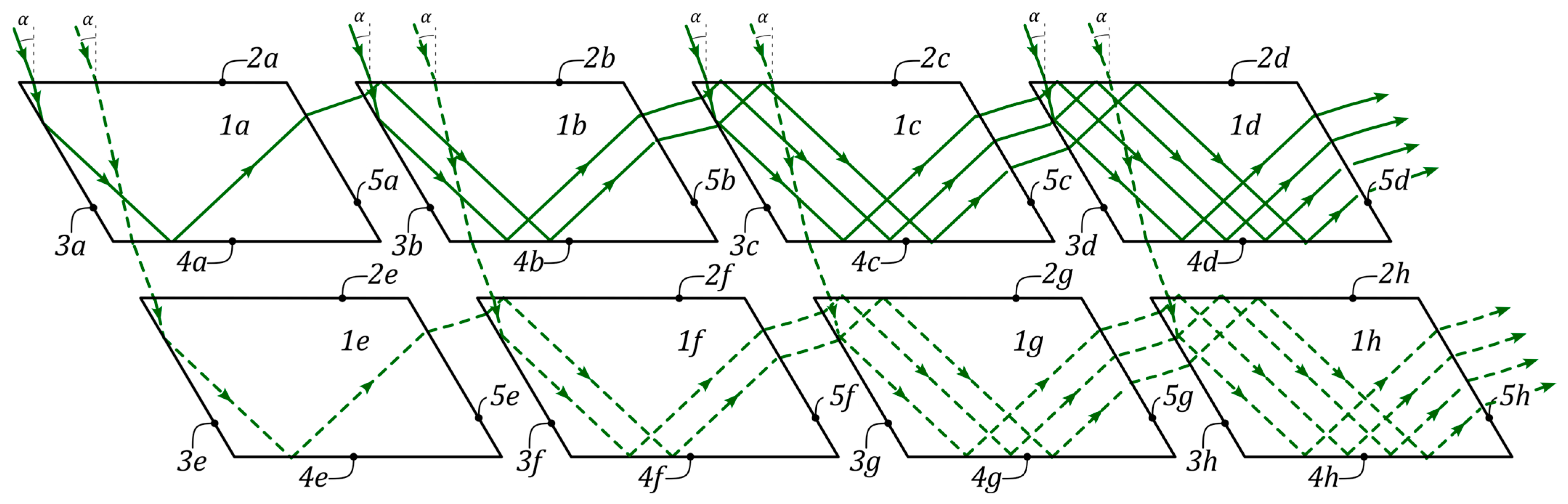
  • Wave Propagation Between Cells: As depicted in Figure 9, an electromagnetic wave exits the first plate (1a) and propagates through the air to the adjacent cell (1b) in the row.
  • Refraction at the Next Cell: The wave enters the end surface (3b) of the plate (1b) and is refracted due to the difference in refractive indices n 0 λ and n 1 ( λ ) .
  • Reflection Within the Cell: The wave propagates along plate (1b) toward the receiving surface (2b), where it undergoes TIR toward the opposite surface (4b).
  • Second Reflection and Propagation: The wave is reflected again from the surface (4b) via TIR and propagates toward the end surface (5b).
  • Repetition Across Cells: The wave exits plate (1b), and the process repeats for each subsequent cell in the row. The propagation concludes at the exit of the final cell, after which the wave travels to the radiation receiver (not shown in Figure 9).
  • Waves Incident on Intermediate Cells: If waves strike the receiving surfaces (2a or 2b) of plates (1a and 1b) that are not at the row’s beginning, the process described above repeats for each respective cell.
  • Waves Missing End Surfaces: Waves that strike the receiving surfaces (2a and 2d) but, due to refraction, miss the end surfaces (3a and 3d) exit through surfaces (4a and 4d) and propagate to the next row of plates (1e and 1h). The process repeats for each cell in the new row.
  • Waves Passing Through Multiple Rows: Waves that do not strike the end surfaces of any plate pass through the rows until they reach the last row, where they finally interact with the end surfaces, repeating the described process.
Optimization of Cell Arrangement
The planar solar concentrator, as shown in Figure 10, can consist of 2 to N y rows of unit cells spaced Y apart. Each row is horizontally offset by Δ x , with all side faces lying in the same plane. The maximum number of rows N y is determined by ensuring that all rays incident on the first row’s receiving surfaces strike the left side edge of the last row.
For a single electromagnetic wave, the wave shifts horizontally by X γ = d · tan γ after refraction on the receiving surface (2a). Upon exiting the cell, the wave’s propagation angle remains unchanged, resulting in an additional shift of X α = Y · tan α over the distance Y between rows. The lateral displacement of each row’s side surface is given by
X β + X Δ = d + Y · tan β ,
except for the first row, which only contributes
X β = d · tan β .
The criterion for determining N y is that the lateral displacement of the side faces must exceed the wave’s horizontal shift. This leads to the following inequality:
N y d = tan 2 β γ + tan γ ( tan β tan γ ) Y ( tan β tan α ) ,
where Y = d n , and n is a natural number between 1 and 10. Values of n < 1 increase the concentrator’s size, while n > 10 complicates assembly and alignment.
Figure 11 shows the result of modeling the number of rows N y in a planar solar concentrator depending on the angle of incidence of radiation on the receiving surface of the cell and depending on the refractive index of the material from which the cell is made. The figure shows that in the region of small angles of incidence, there is an increase in the number of rows to capture all the radiation. This value can reach up to 14 rows. It was previously found that the optimum AA of the cell is in the range of 24 ° to 90 ° (the right border of the region is not included), and in this region, the maximum number of rows is already 7. This result was achieved with β = 43 ° and a cell gap value Y = d 10 .
Figure 11 shows the modeled number of rows N y as a function of the incident angle α and the cell’s refractive index n 1 ( λ ) . For small angles of incidence, up to 14 rows may be required to capture all radiation. However, within the optimal AA range of 24 ° α < 90 ° , the maximum number of rows is 7, achieved with β = 43 °   and Y = d 10 .
GCR Calculation
For a concentrator with N y = 7 rows and one cell per row, the GCR is the ratio of the receiving face area of the first cell to the total side face area of all cells. The receiving face area is
D 0   b i g = X β + X 2 β γ ,
where X β = d · tan β , and X 2 β γ = d · tan ( 2 β γ ) . The side face area is
D 1   b i g = d + N y · ( d + Y ) cos β ,
where Y = d n . The GCR is
G C R = cos β · ( d · tan β + d · tan ( 2 β γ ) ) d + N y · ( d + Y ) .  
For n = 10 , this simplifies to
G C R = cos β · ( tan β + tan ( 2 β γ ) ) 1 + 1.1 · N y .
Figure 12 shows the GCR distribution for this configuration. The GCR remains below 1, with an average value of 0.21 within the optimal AA range.
Gap Between Cells in a Row
The permissible gap X   between cells in a row was calculated by considering the propagation of boundary electromagnetic waves, as shown in Figure 13. The gap must ensure that the outermost ray from the first cell’s side edge strikes the neighboring cell’s side edge:
0 < X d 0.12 .
Maximum Number of Cells per Row
Using Zemax OpticStudio, a full 3D model of the concentrator was created, and ray tracing was performed for the AM0 solar spectrum (280–4000 nm) at incident angles from 24° to 90°. The optimal number of cells per row was found to be N x = 15 .
Final GCR Calculation
The final GCR for the entire concentrator, optimized for N x = 15 and N y = 7 , is
G C R = cos β · tan β + tan 2 β γ + N x ( 0.12 + tan β + tan 2 β γ ) 1 + 1.1 · N y
Figure 14 shows the GCR distribution for this configuration. The GCR exceeds 1, with an average value of 3.45 within the optimal AA range. This demonstrates the concentrator’s ability to efficiently capture and concentrate solar radiation.

4. Discussion

The results of the proposed planar solar concentrator are compared with existing solar energy harvesting devices in Figure 15, which presents a histogram of the GCR and AA for various methods. The comparison highlights the unique advantages and trade-offs of the proposed design relative to established technologies. Below is a detailed analysis of the key findings:
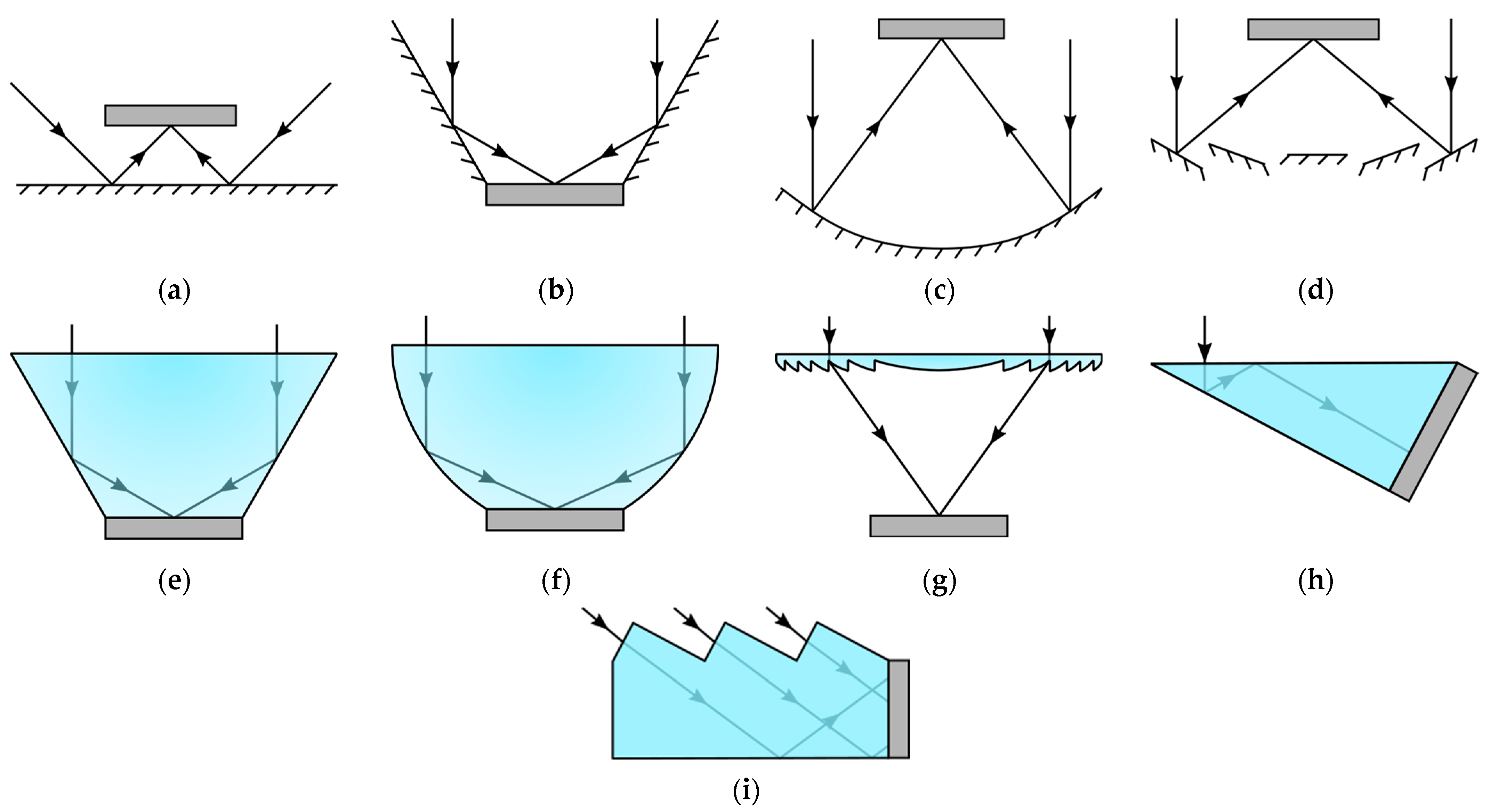
  • Light Funnel/Homogenizer (Method 1): This method achieves a GCR of 1.5 with an AA range of 0° to 20° [3]. While it offers moderate concentration, its limited angular range restricts its applicability in environments with varying solar angles.
  • Flat Mold (Method 2): With a GCR of 2 and an AA of 0° to 1° [4], this method provides higher concentration but is highly sensitive to alignment, making it impractical for most real-world applications.
  • V-Shaped Trough (Method 3): This design achieves a GCR of 2 and an AA of 0° to 20° [5]. Although it offers a wider angular range than Method 2, its concentration efficiency remains relatively low.
  • Wedge Prism (Method 4): This method achieves a higher GCR of 3.77 with an AA of 0° to 50° [6]. Its broader angular range makes it more versatile, but its concentration efficiency is still limited compared to more advanced designs.
  • Compound Parabolic Concentrator (Method 5): With a GCR of 4 and an AA of 0° to 20° [8], this method offers improved concentration but remains constrained by its narrow angular range.
  • Linear Fresnel Reflector (Method 6): This design achieves a GCR ranging from 6 to 15, with an AA of 0° to 1° [10]. While it provides high concentration, its extreme sensitivity to alignment limits its practicality.
  • Parabolic Shape (Method 7): This method achieves a GCR of 70 with an AA of 0° to 0.26° [12]. Although it offers exceptional concentration, its extremely narrow angular range makes it unsuitable for applications requiring flexibility in solar tracking.
  • Fresnel Lens (Method 8): With a GCR of 1000 and an AA of 0° to 1.3° [13], this method provides the highest concentration among the compared technologies. However, its narrow angular range and complexity in manufacturing and alignment pose significant challenges.
  • Proposed Planar Solar Concentrator: The proposed design achieves a GCR of 3.45 with an AA of 23° to 90° (excluding boundaries). This represents a significant improvement in angular range compared to most existing methods, making it highly adaptable to varying solar angles without requiring precise alignment. While its GCR is lower than that of parabolic or Fresnel lens-based systems, its broad AA and simplicity in design and assembly make it a promising solution for practical applications, particularly in environments where solar tracking is impractical or cost-prohibitive.
Key Advantages of the Proposed Design
  • wide range of incident angles (23° to 90°), making it suitable for stationary installations and regions with significant seasonal variations in solar elevation.
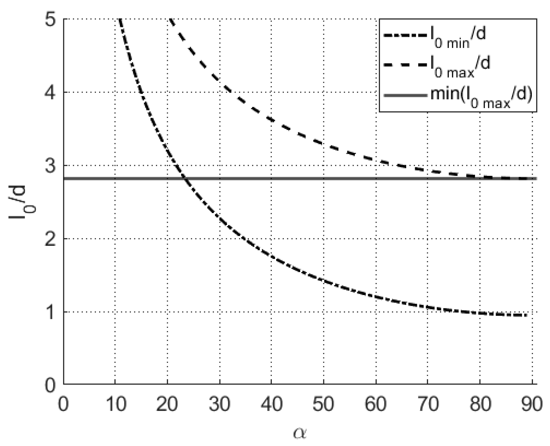
  • Simplified Design and Assembly: The use of identical plane-parallel plates with a fixed inclination angle ( β = 43 ° ) and a length-to-thickness ratio of l 0 d = 2.81 simplifies manufacturing and assembly processes.
  • Material Efficiency: The design minimizes the use of optical materials, reducing both cost and weight while maintaining performance.
  • Scalability: The modular nature of the design allows for easy scaling by adjusting the number of rows ( N y ) and cells per row ( N x ).
Figure 15. Comparative analysis of the obtained simulation results of the planar solar concentrator concept with the existing different analogues: (a) GCR and (b) AA.
Optics 06 00006 g015

5. Conclusions

This paper presents a comprehensive calculation and modeling study conducted using MATLAB software, grounded in the principles of geometrical optics. The study culminates in the development of a novel planar solar concentrator designed for operation in a medium with a refractive index of n 0 = 1 . The concentrator comprises at least one row of unit cells, each of which is an identical plane-parallel plate with mutually parallel end surfaces inclined at an angle β = 43 ° relative to the normal of the receiving surfaces. The material used for the concentrator cells has a refractive index n 1 λ within the range of 1.47 to 1.61 and is optically transparent across the wavelength range λ of 0.3 to 2.5 μm.
The cells are spaced at a distance X from one another, with the length l 0 and thickness d of each plate, as well as the spacing X , selected based on the following conditions: l 0 d = 2.81 and 0 < X d 0.12 . These parameters ensure optimal performance and alignment of the concentrator cells.
To validate the proposed design, the configuration of the planar solar concentrator was thoroughly investigated using the commercial ray-tracing software Zemax OpticStudio. A total of 106 rays across the entire AM0 solar spectrum (280–4000 nm) were traced to evaluate the system’s performance. The results confirmed that the optimal configuration consists of N x = 15 cells per row and N y = 7 rows, with the distance between rows Y = d n , where n is a natural number between 1 and 10. The value of n can be adjusted based on specific design requirements and constraints.
The GCR of the developed concentrator was determined to be GCR = 3.45, with an AA range of 23° to 90° (excluding boundaries). This combination of moderate concentration efficiency and broad AA makes the proposed design highly adaptable to varying solar angles, offering a practical and efficient solution for solar energy harvesting applications. The findings of this study contribute to the advancement of planar solar concentrator technology, providing a scalable and cost-effective approach to renewable energy systems.

Author Contributions

Conceptualization, N.S.; methodology, N.S. and M.K.; software, N.S.; validation, M.K., I.P. and S.K.; formal analysis, I.P.; investigation, N.S. and I.P.; resources, M.K. and S.K.; data curation, N.S.; writing—original draft preparation, N.S., M.K. and I.P.; writing—review, and editing, M.K.; visualization, N.S. and I.P.; supervision, M.K. and S.K.; project administration, M.K.; funding acquisition, M.K. All authors have read and agreed to the published version of the manuscript.

Funding

The study was supported by the Ministry of Science and Higher Education of the Russian Federation, the agreement no. 075-15-2023-612.

Data Availability Statement

The raw data supporting the conclusions of this article will be made available by the authors on request.

Conflicts of Interest

The authors declare no conflicts of interest.

Abbreviations

The following abbreviations are used in this manuscript:
GCRGeometrical concentration ratio
AAAcceptance angle
TIRTotal internal reflection

References

  1. Ballif, C.; Haug, F.-J.; Boccard, M.; Verlinden, P.J.; Hahn, G. Status and perspectives of crystalline silicon photovoltaics in research and industry. Nat. Rev. Mater. 2022, 7, 926. [Google Scholar] [CrossRef]
  2. Sharma, V.K.; Singh, R.; Gehlot, A.; Buddhi, D.; Braccio, S.; Priyadarshi, N.; Khan, B. Imperative Role of Photovoltaic and Concentrating Solar Power Technologies towards Renewable Energy Generation. Int. J. Photoenergy 2022, 13, 3852484. [Google Scholar] [CrossRef]
  3. Shanks, K.; Senthilarasu, S.; Mallick, T.K. Optics for concentrating photovoltaics: Trends, limits and opportunities for materials and design. Renew. Sustain. Energy Rev. 2016, 60, 394–407. [Google Scholar] [CrossRef]
  4. Ma, X.; Zheng, H.; Liu, S. A Review on Solar Concentrators with Multi-surface and Multi-element Combinations. J. Daylighting 2019, 6, 80–96. [Google Scholar] [CrossRef]
  5. Xie, W.; Dai, Y.; Wang, R.; Sumathy, K. Concentrated solar energy applications using Fresnel lenses: A review. Renew. Sustain. Energy Rev. 2011, 15, 2588–2606. [Google Scholar] [CrossRef]
  6. Khamooshi, M.; Salati, H.; Egelioglu, F.; Hooshyar Faghiri, A.; Tarabishi, J.; Babadi, S. A Review of Solar Photovoltaic Concentrators. Int. J. Photoenergy 2014, 958521, 17. [Google Scholar] [CrossRef]
  7. Fu, L.; Leutz, R.; Annen, H.P. Secondary optics for Fresnel lens solar concentrators. In Proceedings of the SPIE OPTICAL ENGINEERING + APPLICATIONS, San Diego, CA, USA, 1–5 August 2010. [Google Scholar]
  8. Soule, D.E. Hybrid Solar Energy Generating System. U.S. Patent 4,700,013, 13 October 1987. [Google Scholar]
  9. Tremblay, R. Electromagnetic Wave Concentrator. U.S. Patent US4505264A, 27 December 1983. [Google Scholar]
  10. Miller, O.E.; McLeod, J.H.; Sherwood, W.T. Thin Sheet Plastic Fresnel Lenses of High Aperture. J. Opt. Soc. Am. 1951, 41, 807–814. [Google Scholar] [CrossRef]
  11. Pociask-Bialy, M. Polyethylene Protective Coating with Anti-Reflective Properties for Silicon Photovoltaic Cells. Materials 2023, 16, 4004. [Google Scholar] [CrossRef]
  12. Price, H.; Lupfert, E.; Kearney, D.; Zarza, E.; Cohen, G.; Gee, R.; Mahoney, R. Advances in Parabolic Trough Solar Power Technology. J. Sol. Energy Eng. ASME 2002, 124, 109–125. [Google Scholar] [CrossRef]
  13. Buljan, M.; Mendes-Lopes, J.; Benítez, P.; Miñano, J.C. Recent trends in concentrated photovoltaics concentrators’ architecture. J. Photon. Energy 2014, 4, 040995. [Google Scholar] [CrossRef]
  14. Weber, K.J.; Everett, V.; Deenapanray, P.N.K.; Franklin, E.; Blakers, A.W. Modeling of static concentrator modules in-corporating lambertian or v-groove rear reflectors. Sol. Energy Mater. Sol. Cells 2006, 90, 1741–1749. [Google Scholar] [CrossRef]
  15. Yu, Y.; Liu, N.; Li, G.; Tang, R. Performance comparison of CPCs with and without exit angle restriction for concentrating radiation on solar cells. Appl. Energy 2015, 155, 284–293. [Google Scholar] [CrossRef]
  16. Yu, Y.; Tang, R. Diffuse reflections within CPCs and its effect on energy collection. Sol. Energy 2015, 120, 44–54. [Google Scholar] [CrossRef]
  17. Tang, R.; Liu, X. Optical performance and design optimization of V-trough concentrators for photovoltaic applications. Sol. Energy 2011, 85, 2154–2166. [Google Scholar] [CrossRef]
  18. Canavarro, D.; Chaves, J.; Collares-Pereira, M. Manuel New second-stage concentrators (XX SMS) for parabolic primaries; Comparison with conventional parabolic trough concentrators. Sol. Energy 2013, 92, 98–105. [Google Scholar] [CrossRef]
  19. Murphree, Q. Point focusing double parabolic trough concentrator. Sol. Energy 2001, 70, 85–94. [Google Scholar] [CrossRef]
  20. Canavarro, D.; Chaves, J.; Collares-Perreira, M. New Optical Designs for Large Parabolic Troughs. Energy Procedia 2014, 49, 1279–1287. [Google Scholar] [CrossRef]
  21. Collares-Pereira, M.; Gordon, J.; Rabl, A.; Winston, R. High concentration two-stage optics for parabolic trough solar collectors with tubular absorber and large rim angle. Sol. Energy 1991, 47, 457–466. [Google Scholar] [CrossRef]
  22. El Gharbi, N.; Derbal-Mokrane, H.; Bouaichaoui, S.; Said, N. A comparative study between parabolic trough collector and linear Fresnel reflector technologies. Energy Procedia 2011, 6, 565–572. [Google Scholar] [CrossRef]
  23. Abbas, R.; Montes, M.J.; Piera, M.; Martínez-Val, J.M. Solar radiation concentration features in Linear Fresnel Reflector arrays. Energy Convers. Manag. 2012, 54, 133–144. [Google Scholar] [CrossRef]
  24. Abbas, R.; Muñoz-Antón, J.; Valdés, M.; Martinez-Val, J. High concentration linear Fresnel reflectors. Energy Convers. Manag. 2013, 72, 60–68. [Google Scholar] [CrossRef]
  25. Selvanayagam, B.F.; Krishnamoorthy, S.; Gowtham, S.; Balaji, N. A review of parabolic collector with shell and tube heat exchanger. Mater. Today Proc. 2022, 66, 1382–1388. [Google Scholar] [CrossRef]
  26. Mills, D.R.; Morrison, G.L. Compact Linear Fresnel Reflector solar thermal powerplants. Sol. Energy 2000, 68, 263–283. [Google Scholar] [CrossRef]
  27. Omer, S.; Infield, D. Design and thermal analysis of a two stage solar concentrator for combined heat and thermo-electric power generation. Energy Convers. Manag. 2000, 41, 737–756. [Google Scholar] [CrossRef]
  28. Tang, R.; Wang, J. A note on multiple reflections of radiation within CPCs and its effect on calculations of energy collection. Renew. Energy 2013, 57, 490–496. [Google Scholar] [CrossRef]
  29. Yu, X.; Su, Y.; Zheng, H.; Riffat, S. A study on use of miniature dielectric compound parabolic concentrator (dCPC) for daylighting control application. Build. Environ. 2011, 74, 75–85. [Google Scholar] [CrossRef]
  30. Chaoqing, F.; Hongfei, Z.; Rui, W.; Xu, Y.; Yuehong, S. A novel solar multifunctional PV/T/D system for green building roofs. Energy Convers. Manag. 2015, 93, 63–71. [Google Scholar]
  31. Li, X.; Dai, Y.; Li, Y.; Wang, R. Comparative study on two novel intermediate temperature CPC solar collectors with the U-shape evacuated tubular absorber. Sol. Energy 2013, 93, 220–234. [Google Scholar] [CrossRef]
  32. Benítez, P.; Miñano, J.C.; Zamora, P.; Mohedano, R.; Cvetkovic, A.; Buljan, M.; Chaves, J.; Hernández, M. High performance Fres-nel-based photovoltaic concentrator. Opt. Express 2010, 26, A25–A40. [Google Scholar] [CrossRef]
  33. Pham, T.T.; Vu, N.H.; Shin, S. Novel Design of Primary Optical Elements Based on a Linear Fresnel Lens for Concentrator Photovoltaic Technology. Energies 2019, 12, 1209. [Google Scholar] [CrossRef]
  34. Fabian, L.; Karl, F.; Cédric, L.; Jérôme, L.; Donat, R.; Tanguy, T.; Serge, H. Flat Fresnel doublets made of PMMA and PC: Combining low cost production and very high concentration ratio for CPV. Opt. Express 2011, 19, A280–A294. [Google Scholar]
  35. Waritanant, T.; Boonruang, S.; Chung, T.-Y. High angular tolerance thin profile solar concentrators designed using a wedge prism and diffraction grating. Sol. Energy 2013, 87, 35–41. [Google Scholar] [CrossRef]
  36. Hughes, M.; Maher, C.; Borca-Tasciuc, D.A.; Polanco, D.; Kaminski, D. Performance comparison of wedge-shaped and planar luminescent solar concentrators. Renew. Energy 2013, 52, 266–272. [Google Scholar] [CrossRef]
  37. Lin, H.-H.; Yang, W.-H. Light Concentration Module. U.S. Patent US20140196785A1, 24 October 2013. [Google Scholar]
  38. Ramachandran, A.M.; Thampi, A.S.; Singh, M.; Asok, A. A comprehensive review on optics and optical materials for planar waveguide-based compact concentrated solar photovoltaics. Results Eng. 2022, 16, 100665. [Google Scholar] [CrossRef]
Figure 1. Schematic simplified images of the basic elements of solar concentrators of the type: (a) Flat reflector [14]; (b) V-trough [15,16,17]; (c) Parabolic dish/trough [18,19,20,21]; (d) Linear Fresnel reflector [22,23,24,25,26,27]; (e) Light funnel/homogenizer [7,28]; (f) Compound parabolic concentrator [29,30,31]; (g) Fresnel lens [32,33,34]; (h) Wedge prism [35,36]; (i) Wedge prism with planar waveguide [37].
Optics 06 00006 g001
Figure 2. Schematic representation of electromagnetic wave propagation in one cell of the claimed solar concentrator is shown.
Optics 06 00006 g002
Figure 3. Dependence of the angle of propagation of radiation γ inside the cell on the refractive index n 1 and the angle of incidence α .
Optics 06 00006 g003
Figure 4. Operating area of the solar concentrator as a function of α , β and n 1 λ .
Optics 06 00006 g004
Figure 5. Beam path and basic values used in the calculations for the GCR and for (a) minimum and (b) maximum unit cell length.
Optics 06 00006 g005
Figure 6. GCR value of a unit cell of a planar solar concentrator depending on the angle of incidence of radiation on the receiving surface of the cell and depending on the refractive index of the material from which the cell is made (the color school corresponds to the quantitative value of the GCR coefficient).
Optics 06 00006 g006
Figure 7. Graphical illustration of the solution region of the system of inequalities (7) for the case when (a) the minimum length ( l 0   m i n d ) and (b) the maximum length ( l 0   m a x d ) of a unit cell are calculated. The color school corresponds to the value of the parameter.
Optics 06 00006 g007
Figure 8. Dependence of the minimum ( l 0   m i n d ) and maximum length ( l 0   m a x d ) of the solar concentrator cell on the angle of incidence α .
Optics 06 00006 g008
Figure 9. A schematic representation of electromagnetic wave propagation in a claimed solar concentrator, according to a partial embodiment, is shown.
Optics 06 00006 g009
Figure 10. The course of the rays and the basic values used in calculating the distance Y between the rows and their number.
Optics 06 00006 g010
Figure 11. Simulation of the number of rows N y in a planar solar concentrator depending on the angle of incidence of radiation on the receiving surface of the cell and depending on the refractive index of the material from which the cell is made (color school corresponds to the number of required rows).
Optics 06 00006 g011
Figure 12. Modeling of the GCR coefficient depending on the angle of incidence of radiation on the receiving surface of the cell and depending on the refractive index of the material from which the cell is made, if the planar solar concentrator consists of N y = 7 number of rows, but in each row, there is only one cell in the planar solar concentrator (the color school corresponds to the quantitative value of the GCR coefficient).
Optics 06 00006 g012
Figure 13. The course of rays and the basic values used in calculating the distance X between cells in one row of rows and their number.
Optics 06 00006 g013
Figure 14. Modeling of the GCR coefficient depending on the angle of incidence of radiation on the receiving surface of the cell and depending on the refractive index of the material from which the cell is made, if a planar solar concentrator consists of N x = 15 number of cells in one row, and such rows N y = 7 (the color school corresponds to the quantitative value of the GCR coefficient).
Optics 06 00006 g014
Table 1. The main types of solar concentrator base elements and their typical characteristics.
TypeOperation MechanismGCR (arb. Units)AA (°)
Flat reflectorReflective coating21
V-troughReflective coating220
Parabolic dish/troughReflective coating700.26
Linear Fresnel reflectorReflective coating6–151
Light funnel/
homogenizer
Refractive and Total internal reflection (TIR)1.520
Compound parabolic concentratorRefractive and TIR420
Fresnel lensRefractive10001.3
Wedge prismRefractive and TIR or reflective coating3.7750
Wedge prism with planar waveguideRefractive and TIR or reflective coating45
Disclaimer/Publisher’s Note: The statements, opinions and data contained in all publications are solely those of the individual author(s) and contributor(s) and not of MDPI and/or the editor(s). MDPI and/or the editor(s) disclaim responsibility for any injury to people or property resulting from any ideas, methods, instructions or products referred to in the content.

