Article

Reduced Graphene Oxide Decorated Titanium Nitride Nanorod Array Electrodes for Electrochemical Applications

1
Department of Chemistry, Virginia Commonwealth University, Richmond, VA 23284-2006, USA
2
Department of Physics, Virginia Commonwealth University, Richmond, VA 23284-2000, USA
*
Authors to whom correspondence should be addressed.
Electrochem 2024, 5(3), 274-286; https://doi.org/10.3390/electrochem5030017
Submission received: 16 May 2024 / Revised: 10 June 2024 / Accepted: 14 June 2024 / Published: 3 July 2024
(This article belongs to the Collection Feature Papers in Electrochemistry)

Abstract

:
This work describes the fabrication and characterization of a new high surface area nanocomposite electrode containing reduced graphene oxide (rGO) and titanium nitride (TiN) for electrochemical applications. This approach involves electrochemically depositing rGO on a high surface area TiN nanorod array electrode to form a new nanocomposite electrode. The TiN nanorod array was first formed by the glancing angle deposition technique in a DC (Direct Current) sputtering system. GO flakes of ~1.5 μm in diameter, as confirmed by Dynamic Light Scattering (DLS), were electrodeposited on the nanostructured TiN electrode via the application of a fixed potential for one hour. The surface morphology of the as-prepared rGO/TiN electrode was evaluated by scanning electron microscopy (SEM) and the presence of rGO on TiN was confirmed by Raman Microscopy. The CV shows an increase in the capacitive current at rGO/TiN as compared to TiN. The rGO decorated TiN electrode was then used for analyzing the electrocatalytic oxidation of ascorbic acid and dopamine, and the reduction of nitrate by CV and linear sweep voltammetry (LSV), respectively. CV or LSV show that the electrochemical kinetics of these three analytes are significantly faster on rGO/TiN than TiN itself. Overall, the rGO/TiN electrode showed better electrochemical behavior for biomolecules like ascorbic acid and dopamine as well as another target analyte, nitrate ions, compared to TiN by itself.

1. Introduction

With its sp2 carbon atoms and pi electrons, graphene is an exciting material with which to fabricate composite materials due to its unique mechanical, thermal, and electronic properties [1,2,3]. Recently, nanocomposites containing graphene such as graphene–noble metals [4], graphene–metal oxides [5], graphene–quantum dots [6], and graphene–polymers [7] have been fabricated and applied in different fields of science. Such graphene-based nanocomposites often show better electrochemical properties than either material on their own. They have thus been used to fabricate electrochemical sensors, supercapacitors, graphene-based lithium-ion batteries, solar cells, and other devices [8,9,10].
One promising material in electrochemical sensing is titanium nitride (TiN) because of its useful properties, including its high melting point, good electrical conductivity, hardness, and chemical stability; it is also much less expensive than noble metals [11,12]. TiN is a promising metal nitride employed for solar cells [13], supercapacitors [14], lithium-ion batteries [15], and biosensors [16]. It has also been proposed as a support for electroanalytical applications [11]. However, more electrochemically active sites need to be incorporated into this material to improve its electrochemical properties. In previous work, we used gold to improve the electrochemical properties of TiN [17] while others have used platinum or palladium [18,19]. Graphene is much less expensive than noble metals and it can provide an easy and useful means to further tune the electrochemical properties improving sensing capabilities. Graphene-TiN composite electrodes, for example, have been used for the detection of dopamine and uric acid [20], acetaminophen and 4-aminophenol [21], NGF (Nerve Growth Factor) [22], BPA (Bisphenol A) [23], and chloramphenicol [24]. In these electrodes, the TiN is either premade and then mixed with graphene oxide (GO) and the GO reduced to rGO [20,21,23] or the Ti precursor (for example, TiO2) is mixed with GO followed by nitridation [22]. To form the composite electrode, typically a suspension of the TiN-rGO dispersed in a suitable solvent is drop cast on a glassy carbon electrode. The former approach is not conducive to the formation of a composite electrode with a nanoporous structure, while the latter does not offer much control over the amount of GO that can be deposited on and within the porous framework.
In this work, we report on a very different approach for the formation of high surface area TiN-rGO electrodes. Rather than starting with a TiN powder, which then has to be mixed with GO and then drop cast or spread on a surface of a conductor such as glassy carbon, we start with a high surface area, nanoporous TiN structure, and then strategically and controllably modify it with rGO using an electrochemically assisted deposition approach. The TiN nanostructures are formed directly on a substrate using glancing angle deposition (GLAD), which is a physical vapor deposition technique used to produce thin films where deposition flux occurs onto a substrate with a large angle with respect to the surface normal while the substrate is rotating [25,26,27,28]. GLAD has been used to produce different nano-sized columnar arrays with controlled porosity and shapes [29,30,31]. It is a powerful and useful approach for preparing nanostructured materials [25,26] because their porosity and surface area-to-volume ratio can be changed, they can be mass-produced, and physical vapor deposition approaches allow for large-area deposition in an economical fashion [28].
One simple and effective approach to controllably decorate the TiN nanorods with rGO and thus form a nanocomposite material with better properties is via electrodeposition. Such an approach takes many forms. A traditional electrodeposition approach involves the reduction of a metal salt at the electrode surface through the transfer of electrons upon application of a suitable cathodic potential (e.g., PtCl4 → Pts). An alternative method involves the electrogeneration of OH through the reduction of nitrate ions and/or water, which causes a significant drop in the pH at the electrode-solution interface and subsequent deposition [32]. In the case of rGO, the application of a sufficiently negative potential to an electrode immersed in a dispersed GO suspension leads to the reduction of GO at/near the electrode surface, resulting in its precipitation on the electrode surface [33,34]. This approach has been used to deposit GO on different electrode surfaces, including gold [35,36,37], copper, nickel, platinum, CoCr alloy [38], glassy carbon [39,40,41], tin oxide [42], Ti [43], and ITO [44].
Unlike simply drop-casting a suspension of chemically reduced GO flakes on a surface, an electrodeposition approach is more controllable and can potentially allow for conformal-like thin films of rGO to be formed on a conductive substrate without the need for volatile solvents or chemical reducing agents [33,34]. It provides a cheap and efficient tool to decorate high surface area materials, such as TiN nanorods, to form a composite material with more electrochemically active sites and thus improved electrochemical properties. By controlling the potential, one can control the extent of the reduction of GO by selective removal of the oxygenated functional groups from GO [45].
In this work, we describe the fabrication of TiN–graphene high surface area nanocomposite electrodes and demonstrate their improved detection of ascorbic acid, dopamine, and nitrate ions. These composite electrodes are made by electrochemically depositing GO on high surface area TiN nanorod array electrodes prepared through GLAD. These new composite electrodes are first characterized using scanning electron microscopy, voltammetry, and Raman spectroscopy. The composite electrodes show much better electrochemical properties than TiN electrodes by themselves, particularly when used to detect ascorbic acid, dopamine, and nitrate ions.

2. Materials and Methods

2.1. Reagents

Potassium chloride (KCl), potassium hydroxide (KOH), potassium phosphate monobasic (KH2PO4), potassium phosphate dibasic (K2HPO4), and L-ascorbic acid (AA) were commercially purchased from VWR CHEMICALS BDH line, Radnor, PA, USA. Sodium sulfate (Anhydrous, Powder) (Na2SO4) and potassium nitrate (KNO3) were purchased from VWR Chemicals J.T. Baker line., Radnor, PA, USA, and Fisher Scientific Co., Ltd., Hampton, NH, USA, respectively. Water (18.2 MΩ cm) was purified using a Millipore water purification system at 25 °C. Graphene oxide (GO) was obtained from Dr. Samy El-Shall’s group in the Department of Chemistry, VCU, and was prepared using the Hummer’s method using high-purity graphite powder as a starting material. All reagents were freshly prepared. All solutions were prepared in 0.1 M phosphate buffer at pH 7.4. Gold (Au) substrates were purchased from EMF Corporation (Ithaca, NY, USA) and consisted of 5 nm of Ti followed by 100 nm of Au coating on float glass slides. The substrates were cut into 10–12 rectangular pieces. The TiN sputtering target (99.5% purity) was purchased from Kurt J. Lesker Co. (Jefferson Hills, PA, USA).

2.2. Graphene-TiN Electrode Fabrication

The electrode fabrication follows two steps: TiN deposition on a planar Au substrate followed by electrochemical deposition of GO on TiN.
(a)
TiN Fabrication
Planar Au substrates were cut into appropriate sizes (~2.5 cm × 0.5 cm) and cleaned by ethanol (190 proof) and ultrapure water for 10 min each successively, followed by sonication, and then dried under N2 gas. The gold slides were then further cleaned in an oxygen plasma (PE 2000 RF Plasma Etcher, South Bay Technology, San Clemente, CA, USA) for 5 min at 25–30 W.
TiN nanorods were deposited on the cleaned Au substrates using the glancing angle deposition (GLAD) technique under an Argon (Ar) environment in a DC (Direct Current) sputtering system. The base pressure of the chamber was lower than 1.0 × 10⁻⁶ Torr, pumped by a turbomolecular pump. The chamber pressure during deposition was adjusted to 1.5 mTorr with a needle-valve-controlled continuous Ar flow. The DC sputtering power was 100 W, and the time of deposition was 45 min. The angle of deposition was 85° as measured between the normal direction of the target surface and the normal of the substrates. The substrates were rotated continuously by a stepper motor at 20 rpm. After the deposition of TiN nanorods, the samples were annealed at 350 °C for 1 h in a tube furnace under a nitrogen gas flow to improve the crystalline structure and electrical properties. The TiN fabrication process is illustrated in Scheme 1.
(b)
rGO electrodeposition
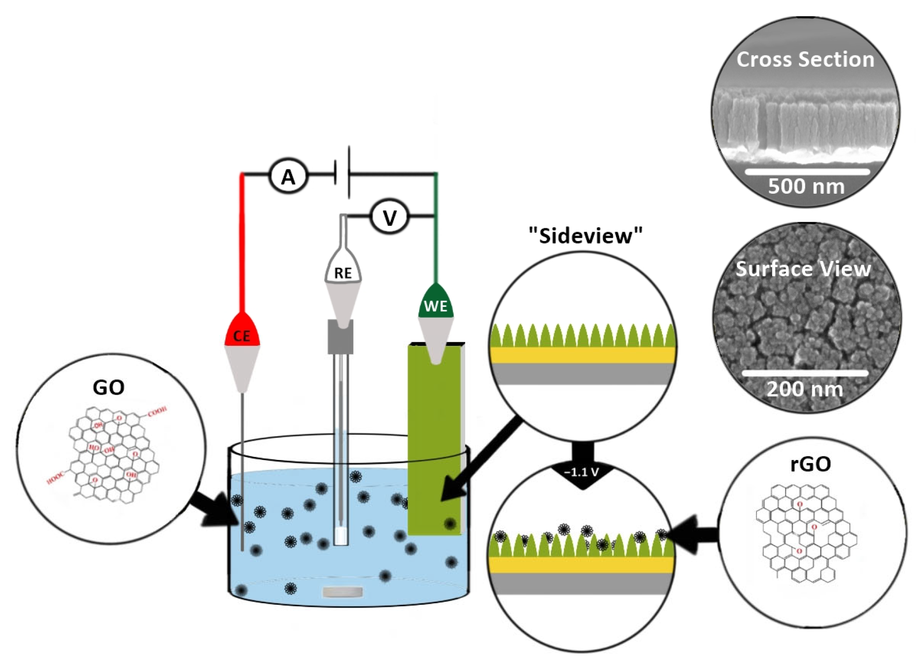
To decorate TiN with rGO, GO (0.714 mg/mL in 0.1 M phosphate buffer (PB), pH 9.0) was first actively sonicated (on (3 s) and off (7 s)) for 30 min with a probe sonicator (Qsonica L.L.C. Sonicators, Newtown, CT, USA; 500 Watts, 20 KHz). A 1 mL aliquot of the as-sonicated GO dispersion was diluted with phosphate buffer and actively sonicated for 60 min to obtain a uniform dispersion ready for electrochemical deposition. The dispersed GO (0.0510 mg/mL in PB of pH 9.0) was electrochemically deposited on the TiN electrode for 60 min while stirring. Potentials ranging from −1.0 to −1.3 V were initially examined, and −1.1 V was chosen as this was the minimum potential needed to electrochemically deposit GO while minimizing background electrolysis reactions. The as-prepared reduced GO decorated TiN (rGO-TiN) was thoroughly rinsed with Milli Q water and dried in an oven at 70 °C for ~20 min. The electrochemical deposition was carried out in a three-electrode electrochemical cell using Ag/AgCl (0.1 M KCl) as the reference electrode and Pt as a counter electrode. The electrochemical deposition process is illustrated in Scheme 2.

2.3. Electrochemical Measurements

Cyclic voltammetric (CV) and linear sweep voltametric (LSV) measurements were carried out in a three-electrode electrochemical cell using a multichannel CH instrument 1000-A potentiostat at a scan rate of 50 mV s−1. The working electrodes were TiN and/or rGO-TiN. Platinum served as a counter electrode and Ag/AgCl as a reference electrode in a frit containing 0.1 M KCl. The supporting electrolyte was 0.1 M PB of pH 7.4. The area of the working electrode area was defined by a piece of adhesive tape with a circular area of 0.32 cm2 cut by a hand punch.

2.4. Instrumentation

The size distribution of the GO was analyzed by dynamic light scattering (DLS) (Malvern Zetasizer Nano-ZS ZEN 3600; WR14 1XZ, UK). The same instrument was used to measure the zeta potential of the GO suspension. The presence of rGO on TiN was confirmed using a Raman spectrometer (Lab RAM HR Evolution Raman Microscope, HORIBA Scientific, Ann Arbor, MI, USA) at an excitation wavelength of 532 nm. Field emission scanning electron microscopy (FE-SEM, SU-70, Hitachi, Schaumburg, IL, USA) was used to evaluate the surface morphology of electrodes after Pt sputtering for 20 s.

3. Results and Discussion

3.1. Electrode Fabrication and Characterization

High surface area electrode materials are very important in electrochemical sensing. When ideally constructed, they can provide higher surface area-to-volume ratios, a greater number of catalytically active sites, and improved electron transfer. In this work, high-surface TiN nanorod array electrodes consisting of vertical nanocolumns with nanosized gaps were made via GLAD. By controlling the angle and rotation, vertical nanorods are formed on the substrate surface resulting from the shadowing effect and the limited surface diffusion mechanisms. First, nanoscale islands form on the surface due to the condensation of atoms and the limited surface diffusion of the deposited atoms. Once the islands are formed, they cast shadows behind them as the incident angle of the atoms is large (at 85° in our experiment) from the surface normal. The shadowing effect prevents the growth of new islands within the shadowed areas. The tip of the island can continue the growth where it is exposed to the incident flux of atoms. As the substrate is rotated uniformly, the shadowed area is a donut shape on the surface with the growing island at the center. As such, vertically aligned nanorods are obtained with the gap between each other controlled by the incident angles. SEM micrographs of the TiN nanorod array utilized in this work along with its corresponding cross-sectional image are illustrated in Figure 1. The top view shows the porosity of electrodes as evidenced by the nanometer gap between TiN nanorods (Figure 1A); the cross-sectional images (Figure 1B) show the TiN vertical nanocolumns. The thickness of the TiN film was evaluated by analyzing the cross-section (Figure 1B) using Image J software and found to be 188.5 ± 5.3 nm. The width of the individual rods is 50.4 ± 13.0 nm (N = 5). X-ray photoelectron spectroscopy of the TiN electrode, which confirmed its chemical makeup, was reported in our previous work [17].
As a means to improve the electrochemical properties, the electrodes were decorated with rGO while maintaining the porous nanostructure of the TiN nanorod framework. To begin, GO particles were first sonicated in 0.1 M phosphate buffer of pH 9.0 by probe sonication to increase dispersity and reduce the particle size; a uniform dispersion of GO aids in the electrodeposition of GO from aqueous suspension. At pH 9, GO has a net negative charge of −46.0 mV, determined from the zeta potential measurements. At high pH values, the carboxylic end groups of GO are deprotonated and more hydrophilic, and thus, the GO remains suspended and dispersed in the solution [46,47]. The size distribution of efficiently sonicated GO was analyzed by DLS and the results are shown in Figure 2. From the graph, the average size of GO flakes was about 1.5 ± 0.4 µm.

3.2. Electrochemical Deposition of GO

To provide control over the deposition of GO on the TiN nanostructure, an electrochemically assisted deposition approach was chosen. This approach is a valuable method to strategically modify an electrode surface with non-conductive and conductive materials in a controlled fashion [32]. It has been routinely used to deposit silica sol-gel-derived materials on electrode surfaces through the electrogeneration of OH [32]. Electrodeposition has also been used to electrochemically reduce GO deposited on a surface via drop casting or by the electrodeposition of GO dispersed in solution, ultimately forming rGO [33,34]. In this work, the latter approach was evaluated as a means to form more active sites on a TiN nanostructured electrode without modifying the inherent porosity of the TiN nanostructure. The mechanism is believed to result from the reduction of carbon-oxygen groups on the surface of GO, thereby reducing hydrophilicity and causing precipitation on the electrode surface [34,40,42,45].
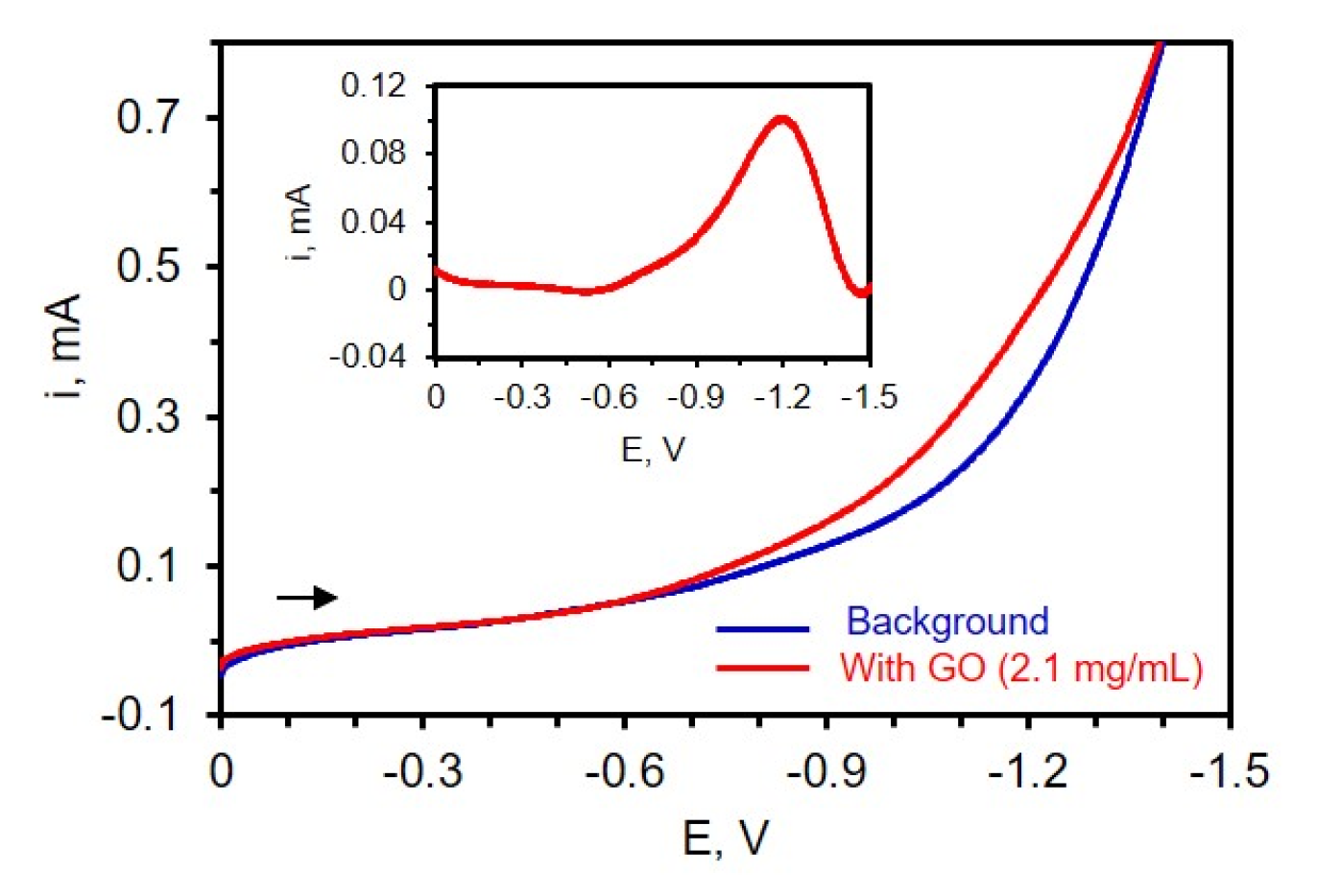
To first determine where the reduction of the carbon-oxygen functionalities takes place on TiN, LSV was carried out at a potential range between 0 and −1.6 V in a three-electrode cell containing dispersed GO in 0.1 M phosphate buffer of pH 9. The solution was deoxygenated for 10 min, and a high concentration of 2.1 mg/mL GO was used in this experiment to better identify where reduction occurs. Figure 3 shows the voltammogram of a TiN electrode immersed in a suspension of GO and the inset depicts the background subtracted LSV. From the background subtracted LSV (Figure 3, inset), a strong reduction peak near −1.2 V is noted, consistent with the literature [35,39], which is attributed to the reduction of oxygen-containing functional groups on the GO surface such as epoxy, aldehyde, and peroxy [39,45].
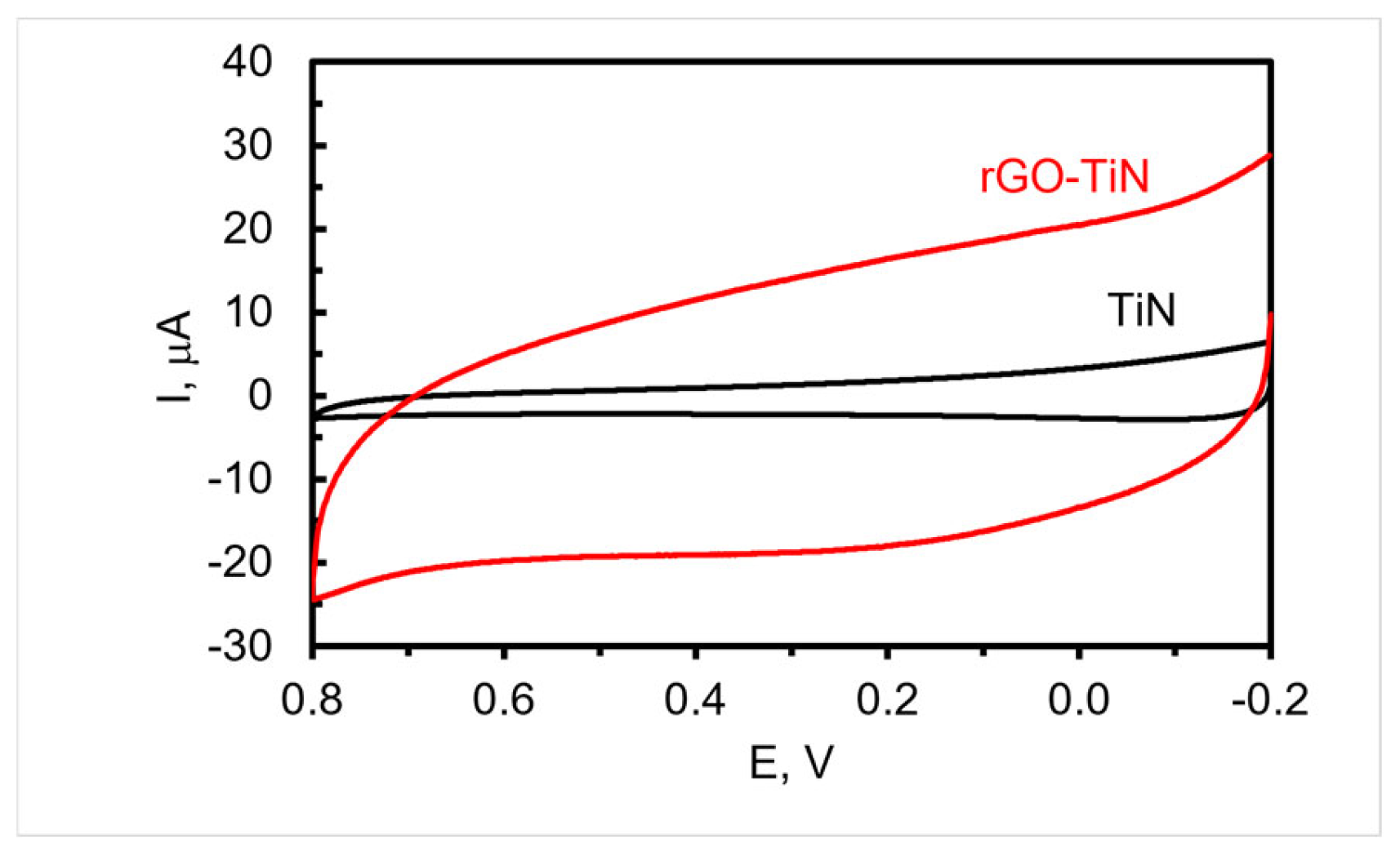
To decorate the TiN nanorod array electrode with rGO, −1.1 V was applied to the electrode immersed in a solution containing dispersed GO for 60 min while stirring followed by thorough rinsing. The CVs of a TiN nanorod electrode in supporting electrolyte before and after the electrodeposition of GO are shown in Figure 4. As can be seen, a quasi-rectangular shape is obtained, which is consistent with other nanostructured TiN composite electrodes containing adsorbed rGO [48] or sputtered with carbon [49]. Furthermore, the non-Faradaic current at the rGO-decorated TiN electrodes is significantly higher than the TiN electrode, which might be due in part to the presence of rGO as it can possibly act to increase the roughness of the electrode, improve wettability, and/or introduce functionalities on the surface with a higher capacitance. Typically, the non-Faradaic current after deposition is four to eight times larger than the original TiN electrode. An estimate of the double-layer capacitance obtained from the CV curve shown in Figure 4 for rGO-TiN is 3.4 × 10⁻⁴ farads (1.1 mF/cm2), which compares well with our previous study [17] but is lower than that reported for TiN sputter coated with carbon for energy storage applications [49].
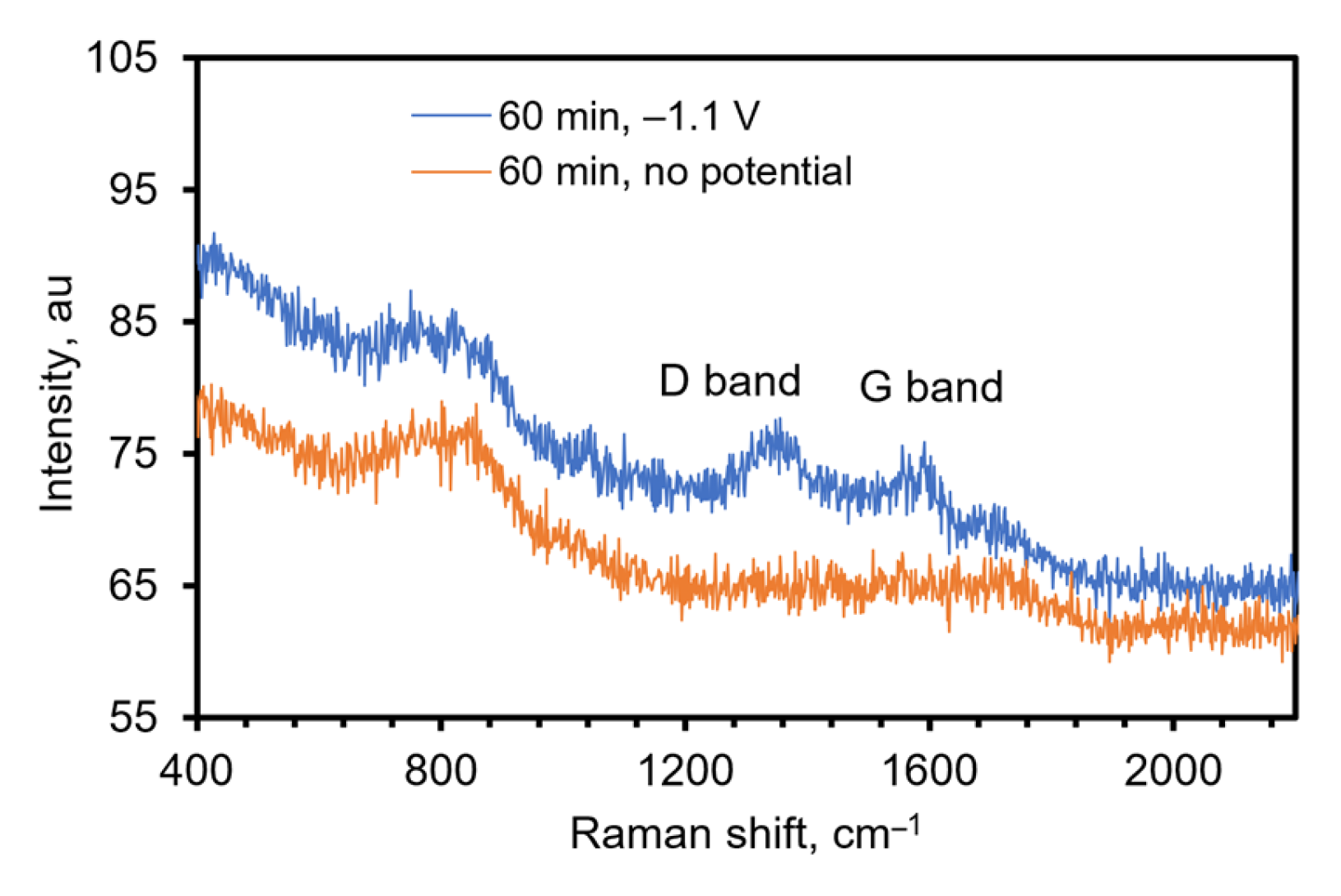
To further confirm the presence of rGO on the electrode, Raman spectroscopy was used. Raman is a powerful analytical tool to identify the disorder and/or defects in graphite and graphene-based substances. The D and G bands are attributed to the disorder in defect sites and sp2 hybridized carbon atoms, respectively [22,50,51]. Figure 5 shows the Raman spectrum obtained using a Raman microscope for a rGO-TiN electrode prepared by electrochemical deposition from a GO solution of 0.0510 mg/mL in 0.1 M PB of pH 9.0 at −1.1 V for 60 min. A control experiment was also undertaken to confirm that the rGO was deposited electrochemically and not through physical adsorption. In this experiment, a TiN electrode was soaked in 0.0510 mg/mL GO in the phosphate buffer solution for 60 min without an applied potential. For the electrode that had a potential applied, D and G bands were observed at 1355 cm−1 and 1591 cm−1, respectively. The spectrum obtained on the control electrode does not show any characteristic D and G bands, indicating the deposition of GO on TiN occurs under electric potential and physical adsorption of GO is not significant. The approximate intensity ratio of the D to the G band is 1.02. This indicates the density of defects in sp2 carbon atoms, and the ratio is increased in most of the electrochemically reduced GO [35,37,39,41]. The number of smaller graphene domains increases with increasing the ratio [41,52].
Given the size of the GO flakes, it is anticipated that the rGO is located on the surface and perhaps between the individual nanorods. Due to the small amount on the surface, we were not able to visualize the graphene flakes via SEM images of the composite electrode.

3.3. Electrocatalytic Activity of TiN and rGO-TiN Electrodes

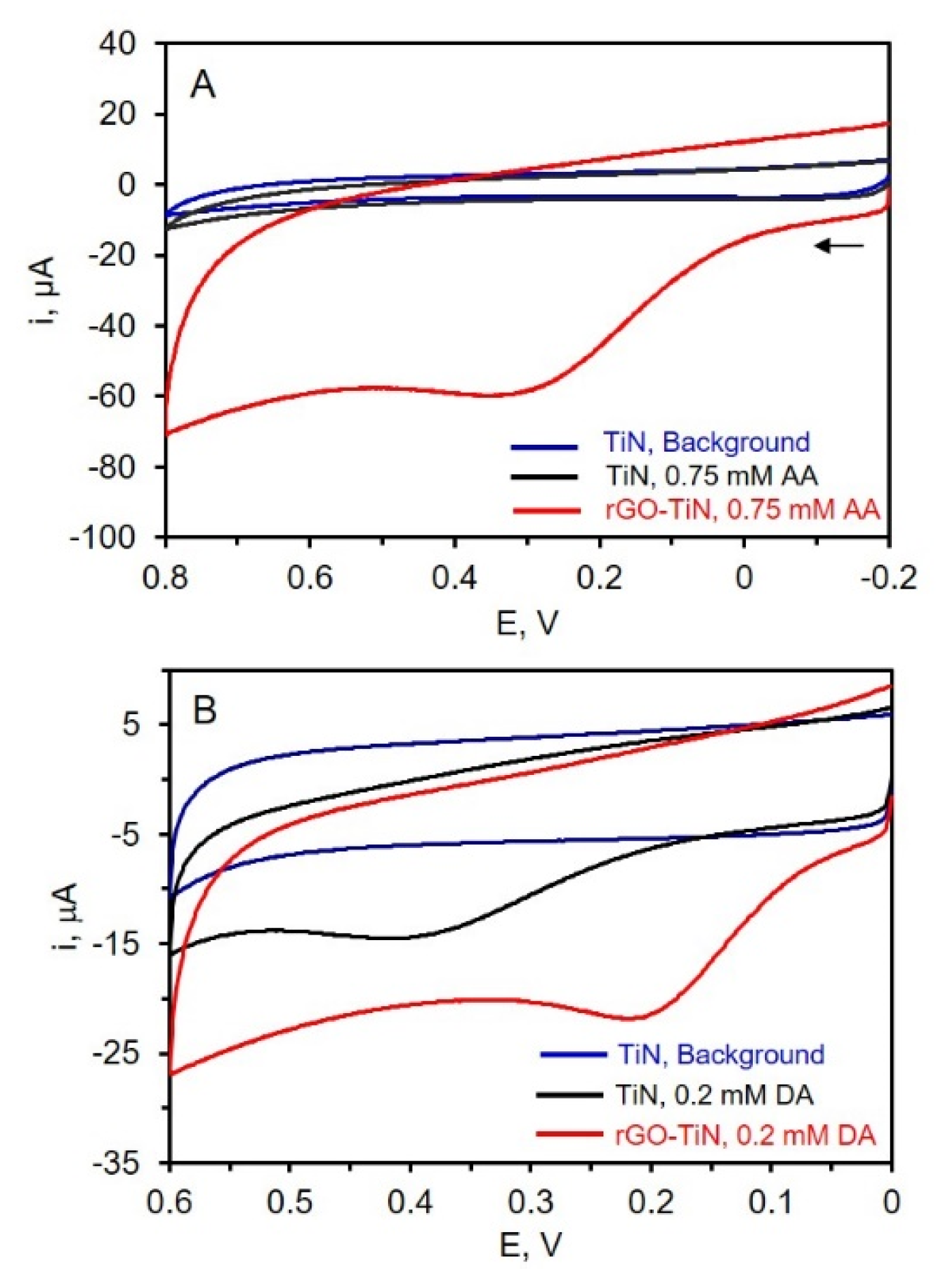
The electrochemical behavior of TiN and rGO-TiN electrodes was evaluated via CV using three different redox molecules: ascorbic acid and dopamine, which are important analytes in biological systems [53] and neurochemistry [54,55], and nitrate, which has environmental implications [56]. The CVs for the oxidation of AA in phosphate buffer at pH 7.4 at the TiN and rGO-TiN electrodes are shown in Figure 6. A TiN electrode was dipped in the suspended GO solution for 60 min with stirring but without an applied potential for the control electrode analysis while GO was electrodeposited on TiN at −1.1 V for 60 min for composite electrode analysis. As can be seen in Figure 6, a small amount of rGO on the TiN nanostructured electrode has a significant effect on the oxidation of AA. First, no oxidation peak is noted at the TiN electrode. In this case, the intrinsic resistance of TiN and slow electron transfer hinders the oxidation of AA at the electrode surface [17]. Significantly larger overpotentials are needed to oxidize AA. At the rGO-TiN electrode, however, a clear oxidation peak for AA is observed, indicating that the decoration of the TiN electrode with rGO introduces needed electrocatalytic sites. The oxidation peak was found at ~0.3 V by rGO-TiN, which is similar to that observed at the chrysanthemum-like TiN electrode formed by drop-casting a suspension of chrysanthemum-like TiN powder on a glassy carbon electrode [57]. It can be seen in Figure 6 that rGO-TiN has higher electrochemical activity toward AA oxidation as compared to TiN itself. The presence of a small amount of rGO certainly improves the electrochemical properties of TiN. This is attributed to various factors including improved electron transfer rates at the rGO-TiN sites, as well as possibly improved wettability, higher surface area, and better conductivity/lower resistance as compared to TiN. Figure 6 also shows the CVs of dopamine at both TiN and rGO-TiN. In this case, dopamine can be oxidized at the TiN electrode due to faster electron-transfer rates at this surface compared to AA. Previous work has suggested the lone pair of electrodes on the N atom and/or hydrogen bonds with the N atoms improves electron transfer [20]. Upon decoration of the TiN electrode with rGO, the overpotential associated with the oxidation of DA is clearly reduced as evidenced by the positive shift in the peak potential. It is much easier to oxidize dopamine at the rGO-TiN as compared to TiN, likely due to reasons such as better electron transfer and perhaps improved wettability. These results indicate that rGO-decorated TiN electrodes could have promise in electrochemical sensing applications, as also suggested by other rGO-TiN composite electrodes [20,21,22,23,24].
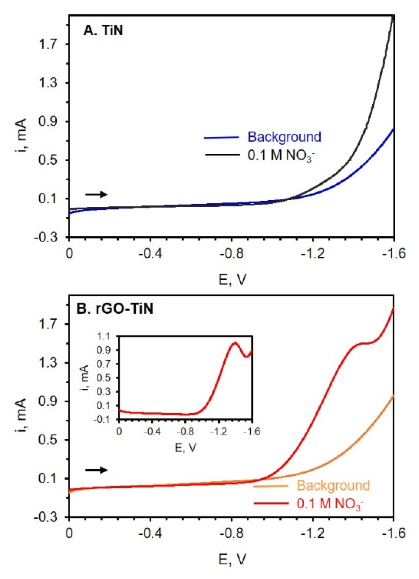
The electrocatalytic efficiency of TiN electrodes with or without GO modification toward nitrate reduction was also analyzed via LSV. Nitrate, in particular, is an important ion that is found in numerous sources such as soil, groundwater, and food [56,58]. Due to the beneficial properties of graphene, graphene-based materials such as rGO-metal oxide, rGO-metal-, and rGO-conductive polymer nanocomposites have shown promise for the detection and quantification of nitrate and nitrite ions [56]. Figure 7 shows the LSVs of TiN and rGO-TiN electrodes in an electrolyte solution with and without nitrate. In this experiment, potassium nitrate (KNO3) was used as the nitrate source, and sodium sulfate (Na2SO4) was used as a suitable electrolyte. GO was electrodeposited on TiN at −1.1 V for 60 min. From the LSVs shown in Figure 7, it can be observed that a small amount of rGO on the TiN nanostructured electrode has a significant effect on the electrochemical reduction of nitrate ions (NO3). At the TiN electrode, no peaks attributed to nitrate reduction can be noted, as shown in Figure 7A. However, at the rGO-TiN electrode, a small peak can be seen near −1.3 V. When the LSV of nitrate reduction was subtracted from the background scan, a peak for the reduction of NO3 can be clearly observed, as shown in Figure 7B. The results indicate that rGO-TiN has better electrocatalytic efficiency than TiN itself toward the reduction of nitrate ions. The addition of these graphitic sites to TiN leads to faster electron exchange rates and a reduced overpotential associated with the reduction of nitrate ions [56].

4. Conclusions

In summary, we have developed an rGO-decorated TiN nanocomposite electrode by a green fabrication route: electrochemical deposition. We show that by applying a sufficiently negative potential to a TiN nanorod array electrode in a solution containing a suspension of GO, rGO can be electrochemically deposited on the TiN nanorod surface. Improved electrochemical properties were obtained by integrating TiN and rGO. The porous nanostructure of the TiN nanorod array electrode remained the same after decoration, preserving the nanopore network. The presence of rGO is evidenced by Raman spectroscopy. TiN-nanorod electrodes decorated with a small amount of rGO were able to detect ascorbic acid, dopamine, and nitrate ions with significantly lower overpotentials as compared to undecorated TiN GLAD electrodes. We believe that these new nanostructured composite electrodes will be useful in electrochemical sensing applications and as supercapacitors. Future work will be directed toward developing methodologies to increase the amount of rGO on the surface, thus further improving the electrocatalytic properties of these new nanocomposite electrodes, as well as evaluating the analytical figures-of-merit of the resultant electrodes in electrochemical sensing applications.

Author Contributions

Conceptualization, D.Y., M.M.C. and M.S.I.; Methodology, D.Y., M.M.C. and M.S.I.; Validation, D.Y., M.M.C., M.S.I. and A.B.; Formal Analysis, M.S.I. and A.B.; Investigation, D.Y., M.M.C. and M.S.I.; Resources, D.Y., M.M.C., M.S.I. and A.B.; Data Curation, M.S.I. and A.B.; Writing—Original Draft Preparation, M.S.I.; Writing—Review and Editing, M.M.C. and D.Y.; Visualization, A.B.; Supervision, D.Y. and M.M.C.; Project Administration, D.Y. and M.M.C.; Funding Acquisition, D.Y. and M.M.C. All authors have read and agreed to the published version of the manuscript.

Funding

This research was funded by the VCU College of Humanities and Sciences Catalyst Award.

Institutional Review Board Statement

Not applicable.

Informed Consent Statement

Not applicable.

Data Availability Statement

Data available upon request.

Acknowledgments

We would like to thank Michael Moody in the M. Samy-El-Shall group for synthesizing graphene oxide and Subrata Banik with some help with the electrochemistry. We are also grateful to the NCC (Nanomaterial Core Characterization Facility) center for providing useful advice and training to use the instrumentation. We thank Junaid Ahmed for acquiring the zeta potential data and the Alvarez group for the use of a probe sonicator. We also thank Carl Meyer and Joseph Turner for their assistance in acquiring the Raman spectra.

Conflicts of Interest

The authors declare no conflicts of interest. The funders had no role in the design of the study; in the collection, analysis, or interpretation of data; in the writing of the manuscript; or in the decision to publish the results.

References

  1. Tiwari, S.K.; Sahoo, S.; Wang, N.; Huczko, A. Graphene research and their outputs: Status and prospect. J. Sci. Adv. Mater. Devices 2020, 5, 10–29. [Google Scholar] [CrossRef]
  2. Razaq, A.; Bibi, F.; Zheng, X.; Papadakis, R.; Jafri, S.H.M.; Li, H. Review on Graphene-, Graphene Oxide-, Reduced Graphene Oxide-Based Flexible Composites: From Fabrication to Applications. Materials 2022, 15, 1012. [Google Scholar] [CrossRef] [PubMed]
  3. Allen, M.J.; Tung, V.C.; Kaner, R.B. Honeycomb carbon: A review of graphene. Chem. Rev. 2010, 110, 132–145. [Google Scholar] [CrossRef] [PubMed]
  4. Tan, C.; Huang, X.; Zhang, H. Synthesis and applications of graphene-based noble metal nanostructures. Mater. Today 2013, 16, 29–36. [Google Scholar] [CrossRef]
  5. Khan, M.; Tahir, M.N.; Adil, S.F.; Khan, H.U.; Siddiqui, M.R.H.; Al-Warthan, A.A.; Tremel, W. Graphene based metal and metal oxide nanocomposites: Synthesis, properties and their applications. J. Mater. Chem. A Mater. 2015, 3, 18753–18808. [Google Scholar] [CrossRef]
  6. Ghaffarkhah, A.; Hosseini, E.; Kamkar, M.; Sehat, A.A.; Dordanihaghighi, S.; Allahbakhsh, A.; van der Kuur, C.; Arjmand, M. Synthesis, Applications, and Prospects of Graphene Quantum Dots: A Comprehensive Review. Small 2022, 18, 2102683. [Google Scholar] [CrossRef] [PubMed]
  7. Sreenivasulu, B.; Ramji, B.R.; Nagaral, M. A Review on Graphene Reinforced Polymer Matrix Composites. Mater. Today Proc. 2018, 5, 2419–2428. [Google Scholar] [CrossRef]
  8. Mbayachi, V.B.; Ndayiragije, E.; Sammani, T.; Taj, S.; Mbuta, E.R.; Ullah Khan, A. Graphene synthesis, characterization and its applications: A review. Results Chem. 2021, 3, 100163. [Google Scholar] [CrossRef]
  9. Santhiran, A.; Iyngaran, P.; Abiman, P.; Kuganathan, N. Graphene Synthesis and Its Recent Advances in Applications—A Review. C 2021, 7, 76. [Google Scholar] [CrossRef]
  10. Ambrosi, A.; Chua, C.K.; Bonanni, A.; Pumera, M. Electrochemistry of graphene and related materials. Chem. Rev. 2014, 114, 7150–7188. [Google Scholar] [CrossRef] [PubMed]
  11. Kirchner, C.N.; Hallmeier, K.H.; Szargan, R.; Raschke, T.; Radehaus, C.; Wittstock, G. Evaluation of thin film titanium nitride electrodes for electroanalytical applications. Electroanalysis 2007, 19, 1023–1031. [Google Scholar] [CrossRef]
  12. Zhong, Y.; Xia, X.H.; Shi, F.; Zhan, J.Y.; Tu, J.P.; Fan, H.J. Transition metal carbides and nitrides in energy storage and conversion. Adv. Sci. 2015, 3, 1500286. [Google Scholar] [CrossRef]
  13. Li, C.T.; Li, S.R.; Chang, L.Y.; Lee, C.P.; Chen, P.Y.; Sun, S.S.; Lin, J.J.; Vittal, R.; Ho, K.C. Efficient titanium nitride/titanium oxide composite photoanodes for dye-sensitized solar cells and water splitting. J. Mater. Chem. A Mater. 2015, 3, 4695–4705. [Google Scholar] [CrossRef]
  14. Achour, A.; Porto, R.L.; Soussou, M.A.; Islam, M.; Boujtita, M.; Aissa, K.A.; Le Brizoual, L.; Djouadi, A.; Brousse, T. Titanium nitride films for micro-supercapacitors: Effect of surface chemistry and film morphology on the capacitance. J. Power Sources 2015, 300, 525–532. [Google Scholar] [CrossRef]
  15. Cui, Z.; Zu, C.; Zhou, W.; Manthiram, A.; Goodenough, J.B. Mesoporous Titanium Nitride-Enabled Highly Stable Lithium-Sulfur Batteries. Adv. Mater. 2016, 28, 6926–6931. [Google Scholar] [CrossRef] [PubMed]
  16. Dong, S.; Chen, X.; Gu, L.; Zhang, L.; Zhou, X.; Liu, Z.; Han, P.; Xu, H.; Yao, J.; Zhang, X.; et al. A biocompatible titanium nitride nanorods derived nanostructured electrode for biosensing and bioelectrochemical energy conversion. Biosens. Bioelectron. 2011, 26, 4088–4094. [Google Scholar] [CrossRef] [PubMed]
  17. Khan, R.K.; Farghaly, A.A.; Silva, T.A.; Ye, D.; Collinson, M.M. Gold-Nanoparticle-Decorated Titanium Nitride Electrodes Prepared by Glancing-Angle Deposition for Sensing Applications. ACS Appl. Nano Mater. 2019, 2, 1562–1569. [Google Scholar] [CrossRef]
  18. Thotiyl, M.M.O.; Kumar, T.R.; Sampath, S. Pd Supported on Titanium Nitride for Efficient Ethanol Oxidation. J. Phys. Chem. C 2010, 114, 17934–17941. [Google Scholar] [CrossRef]
  19. Thotiyl, M.M.O.; Ravikumar, T.; Sampath, S. Platinum particles supported on titanium nitride: An efficient electrode material for the oxidation of methanol in alkaline media. J. Mater. Chem. 2010, 20, 10643. [Google Scholar] [CrossRef]
  20. Feng, J.; Li, Q.; Cai, J.; Yang, T.; Chen, J.; Hou, X. Electrochemical detection mechanism of dopamine and uric acid on titanium nitride-reduced graphene oxide composite with and without ascorbic acid. Sens. Actuators B Chem. 2019, 298, 126872. [Google Scholar] [CrossRef]
  21. Kong, F.Y.; Gu, S.X.; Wang, J.Y.; Fang, H.L.; Wang, W. Facile green synthesis of graphene-titanium nitride hybrid nanostructure for the simultaneous determination of acetaminophen and 4-aminophenol. Sens. Actuators B Chem. 2015, 213, 397–403. [Google Scholar] [CrossRef]
  22. Wei, Z.; Wang, Y.; Zhang, J. Electrochemical detection of NGF using a reduced graphene oxide-titanium nitride nanocomposite. Sci. Rep. 2018, 8, 6929. [Google Scholar] [CrossRef] [PubMed]
  23. Xu, W.; Zhang, Y.; Yin, X.; Zhang, L.; Cao, Y.; Ni, X.; Huang, W. Highly sensitive electrochemical BPA sensor based on titanium nitride-reduced graphene oxide composite and core-shell molecular imprinting particles. Anal. Bioanal. Chem. 2021, 413, 1081–1090. [Google Scholar] [CrossRef] [PubMed]
  24. Kong, F.-Y.; Chen, T.-T.; Wang, J.-Y.; Fang, H.-L.; Fan, D.-H.; Wang, W. UV-assisted synthesis of tetrapods-like titanium nitride-reduced graphene oxide nanohybrids for electrochemical determination of chloramphenicol. Sens. Actuators B Chem. 2016, 225, 298–304. [Google Scholar] [CrossRef]
  25. Zhao, Y.; Ye, D.; Wang, G.-C.; Lu, T.-M. Designing nanostructures by glancing angle deposition. In Nanotubes and Nanowires; SPIE: Bellingham, WA, USA, 2003; p. 59. [Google Scholar] [CrossRef]
  26. Hawkeye, M.M.; Taschuk, M.T.; Brett, M.J. Glancing Angle Deposition of Thin Films: Engineering the Nanoscale; John Wiley & Sons, Ltd.: Hoboken, NJ, USA, 2014. [Google Scholar] [CrossRef]
  27. Robbie, K. Advanced techniques for glancing angle deposition. J. Vac. Sci. Technol. B Microelectron. Nanometer Struct. 1998, 16, 1115. [Google Scholar] [CrossRef]
  28. Krause, K.M.; Taschuk, M.T.; Brett, M.J. Glancing angle deposition on a roll: Towards high-throughput nanostructured thin films. J. Vac. Sci. Technol. A Vac. Surf. Film. 2013, 31, 031507. [Google Scholar] [CrossRef]
  29. Zhao, Y.-P.; Ye, D.-X.; Wang, P.-I.; Wang, G.-C.; Lu, T.-M. Fabrication of Si Nanocolumns and Si Square Spirals on Self-Assembled Monolayer Colloid Substrates. Int. J. Nanosci. 2002, 01, 87–97. [Google Scholar] [CrossRef]
  30. Zhao, Y.-P.; Ye, D.-X.; Wang, G.-C.; Lu, T.-M. Novel Nano-Column and Nano-Flower Arrays by Glancing Angle Deposition. Nano Lett. 2002, 2, 351–354. [Google Scholar] [CrossRef]
  31. Ye, D.-X.; Zhao, Y.-P.; Yang, G.-R.; Zhao, Y.-G.; Wang, G.-C.; Lu, T.-M. Manipulating the column tilt angles of nanocolumnar films by glancing-angle deposition. Nanotechnology 2002, 13, 615–618. [Google Scholar] [CrossRef]
  32. Goux, A.; Etienne, M.; Aubert, E.; Lecomte, C.; Ghanbaja, J.; Walcarius, A. Oriented mesoporous silica films obtained by electro-assisted self-assembly (EASA). Chem. Mater. 2009, 21, 731–741. [Google Scholar] [CrossRef]
  33. Zhou, A.; Bai, J.; Hong, W.; Bai, H. Electrochemically reduced graphene oxide: Preparation, composites, and applications. Carbon 2022, 191, 301–332. [Google Scholar] [CrossRef]
  34. Chen, K.; Chen, L.; Chen, Y.; Bai, H.; Li, L. Three-dimensional porous graphene-based composite materials: Electrochemical synthesis and application. J. Mater. Chem. 2012, 22, 20968–20976. [Google Scholar] [CrossRef]
  35. Liu, C.; Wang, K.; Luo, S.; Tang, Y.; Chen, L. Direct electrodeposition of graphene enabling the one-step synthesis of graphene-metal nanocomposite films. Small 2011, 7, 1203–1206. [Google Scholar] [CrossRef] [PubMed]
  36. Ramesha, G.K.; Sampath, N.S. Electrochemical reduction of oriented Graphene oxide films: An in situ Raman spectroelectrochemical study. J. Phys. Chem. C 2009, 113, 7985–7989. [Google Scholar] [CrossRef]
  37. Peng, X.Y.; Liu, X.X.; Diamond, D.; Lau, K.T. Synthesis of electrochemically-reduced graphene oxide film with controllable size and thickness and its use in supercapacitor. Carbon 2011, 49, 3488–3496. [Google Scholar] [CrossRef]
  38. García-Argumánez, A.; Llorente, I.; Caballero-Calero, O.; González, Z.; Menéndez, R.; Escudero, M.L.; García-Alonso, M.C. Electrochemical reduction of graphene oxide on biomedical grade CoCr alloy. Appl. Surf. Sci. 2019, 465, 1028–1036. [Google Scholar] [CrossRef]
  39. Guo, H.L.; Wang, X.F.; Qian, Q.Y.; Wang, F.B.; Xia, X.H. A green approach to the synthesis of graphene nanosheets. ACS Nano 2009, 3, 2653–2659. [Google Scholar] [CrossRef] [PubMed]
  40. Chen, L.; Tang, Y.; Wang, K.; Liu, C.; Luo, S. Direct electrodeposition of reduced graphene oxide on glassy carbon electrode and its electrochemical application. Electrochem. Commun. 2011, 13, 133–137. [Google Scholar] [CrossRef]
  41. Jiang, Y.; Lu, Y.; Li, F.; Wu, T.; Niu, L.; Chen, W. Facile electrochemical codeposition of “clean” graphene-Pd nanocomposite as an anode catalyst for formic acid electrooxidation. Electrochem. Commun. 2012, 19, 21–24. [Google Scholar] [CrossRef]
  42. Kauppila, J.; Kunnas, P.; Damlin, P.; Viinikanoja, A.; Kvarnström, C. Electrochemical reduction of graphene oxide films in aqueous and organic solutions. Electrochim. Acta 2013, 89, 84–89. [Google Scholar] [CrossRef]
  43. Wang, J.; Min, L.; Fang, F.; Zhang, W.; Wang, Y. Electrodeposition of graphene nano-thick coating for highly enhanced performance of titanium bipolar plates in fuel cells. Int. J. Hydrogen Energy 2019, 44, 16909–16917. [Google Scholar] [CrossRef]
  44. Moghazi, M.A.A.; Al Shareef, S.; Wong, H.Y.; Zaman, M. Synthesis of Graphene on Conducting Substrate by Electrochemical Deposition Method. Am. J. Appl. Sci. 2017, 14, 325–334. [Google Scholar] [CrossRef]
  45. Gao, M.; Xu, Y.; Wang, X.; Sang, Y.; Wang, S. Analysis of Electrochemical Reduction Process of Graphene Oxide and its Electrochemical Behavior. Electroanalysis 2016, 28, 1377–1382. [Google Scholar] [CrossRef]
  46. Kashyap, S.; Mishra, S.; Behera, S.K. Aqueous Colloidal Stability of Graphene Oxide and Chemically Converted Graphene. J. Nanoparticles 2014, 2014, 1–6. [Google Scholar] [CrossRef]
  47. Shih, C.J.; Lin, S.; Sharma, R.; Strano, M.S.; Blankschtein, D. Understanding the pH-dependent behavior of graphene oxide aqueous solutions: A comparative experimental and molecular dynamics simulation study. Langmuir 2012, 28, 235–241. [Google Scholar] [CrossRef] [PubMed]
  48. Tian, F.; Xie, Y.; Du, H.; Zhou, Y.; Xia, C.; Wang, W. Preparation and electrochemical capacitance of graphene/titanium nitride nanotube array. RSC Adv. 2014, 4, 41856–41863. [Google Scholar] [CrossRef]
  49. Shi, J.; Jiang, B.; Li, C.; Liu, Z.; Yan, F.; Liu, X.; Li, H.; Yang, C.; Dong, D.; Hao, J. Study on capacitance properties of the sputtered carbon doped titanium nitride electrode material for supercapacitor. Vacuum 2022, 198, 110893. [Google Scholar] [CrossRef]
  50. Berciaud, S.; Ryu, S.; Brus, L.E.; Heinz, T.F. Probing the Intrinsic Properties of Exfoliated Graphene: Raman Spectroscopy of Free-Standing Monolayers. Nano Lett. 2009, 9, 346–352. [Google Scholar] [CrossRef]
  51. Cançado, L.G.; Jorio, A.; Ferreira, E.H.M.; Stavale, F.; Achete, C.A.; Capaz, R.B.; Moutinho, M.V.O.; Lombardo, A.; Kulmala, T.S.; Ferrari, A.C. Quantifying defects in graphene via Raman spectroscopy at different excitation energies. Nano Lett. 2011, 11, 3190–3196. [Google Scholar] [CrossRef] [PubMed]
  52. Stankovich, S.; Dikin, D.A.; Piner, R.D.; Kohlhaas, K.A.; Kleinhammes, A.; Jia, Y.; Wu, Y.; Nguyen, S.B.T.; Ruoff, R.S. Synthesis of graphene-based nanosheets via chemical reduction of exfoliated graphite oxide. Carbon 2007, 45, 1558–1565. [Google Scholar] [CrossRef]
  53. Cheng, H.; Li, L.; Zhang, M.; Jiang, Y.; Yu, P.; Ma, F.; Mao, L. Recent advances on in vivo analysis of ascorbic acid in brain functions. Trends Anal. Chem. 2018, 109, 247–259. [Google Scholar] [CrossRef]
  54. Lakard, S.; Pavel, I.A.; Lakard, B. Electrochemical biosensing of dopamine neurotransmitter: A review. Biosensors 2021, 11, 179. [Google Scholar] [CrossRef] [PubMed]
  55. Wilson, G.S.; Johnson, M.A. In-vivo electrochemistry: What can we learn about living systems? Chem. Rev. 2008, 108, 2462–2481. [Google Scholar] [CrossRef] [PubMed]
  56. Marlinda, A.R.; An’amt, M.N.; Yusoff, N.; Sagadevan, S.; Wahab, Y.A.; Johan, M.R. Recent progress in nitrates and nitrites sensor with graphene-based nanocomposites as electrocatalysts. Trends Environ. Anal. Chem. 2022, 34, e00162. [Google Scholar] [CrossRef]
  57. Zhang, L.; Feng, J.; Chou, K.C.; Su, L.; Hou, X. Simultaneously electrochemical detection of uric acid and ascorbic acid using glassy carbon electrode modified with chrysanthemum-like titanium nitride. J. Electroanal. Chem. 2017, 803, 11–18. [Google Scholar] [CrossRef]
  58. Wang, Q.H.; Yu, L.J.; Liu, Y.; Lin, L.; Lu, R.G.; Zhu, J.P.; He, L.; Lu, Z.L. Methods for the detection and determination of nitrite and nitrate: A review. Talanta 2017, 165, 709–720. [Google Scholar] [CrossRef]
Scheme 1. Titanium nitride nanorod fabrication by glancing angle deposition.
Electrochem 05 00017 sch001
Scheme 2. Electrochemical deposition of exfoliated GO onto TiN to produce rGO-decorated TiN nanocomposite electrodes. The small silver rod in the deposition solution is the stir bar. The three electrodes represent the counter electrode (CE, platinum), reference electrode (RE; Ag/AgCl (0.1 M KCl)), and the TiN nanorod working electrode (WE).
Electrochem 05 00017 sch002
Figure 1. SEM images of TiN nanorod electrodes prepared by GLAD. (A) Top view and (B) Cross-sectional view.
Electrochem 05 00017 g001
Figure 2. Size distribution of graphene oxide (0.0510 mg/mL in 0.1 M PB of pH 9.0) by dynamic light scattering.
Electrochem 05 00017 g002
Figure 3. Voltammogram of 0.1 M PB of pH 9.0 (blue curve) and after the addition of 2.1 mg/mL of GO (red curve). Inset: Background subtracted voltammogram. The experiment was carried out after 10 min of N2 purging; scan rate 50 mV/s. The reference electrode is Ag/AgCl (0.1 M KCl).
Electrochem 05 00017 g003
Figure 4. CVs acquired in 0.1 M PB of pH 7.4 at TiN (Black) and rGO-TiN (Red) electrodeposited at −1.1 V for 1 h; scan rate 50 mV/s. The reference electrode is Ag/AgCl (0.1 M KCl).
Electrochem 05 00017 g004
Figure 5. Raman spectrum of TiN (control, orange) and rGO-TiN (blue), excitation wavelength 532 nm. The control electrode was made by immersing the TiN electrode in GO solution for 60 min with stirring and no potential was applied.
Electrochem 05 00017 g005
Figure 6. (A) CVs of 0.1 M PB of pH 7.4 at TiN (Blue) and 0.75 mM AA in phosphate buffer at TiN (Black) and rGO-TiN (Red); (B) CVs of 0.1 M PB of pH 7.4 at TiN (Blue) and 0.2 mM DA in phosphate buffer at TiN (Black) and rGO-TiN (Red); scan rate 50 mV/s. The reference electrode is Ag/AgCl (0.1 M KCl).
Electrochem 05 00017 g006
Figure 7. (A) LSV of background electrolyte (0.05 M Na2SO4) (blue curve) at TiN and after addition of 0.1 M KNO3 (black curve) at a TiN electrode. (B) LSV of background electrolyte, 0.05 M Na2SO4, (Orange curve) at rGO-TiN and then after the addition of 0.1 M KNO3 (red curve). Scan rate = 50 mV/s. GO (0.0510 mg/mL in 0.1 M PB of pH 9.0) was electrodeposited on TiN at −1.1 V for 60 min followed by rinsing. The reference electrode is Ag/AgCl (0.1 M KCl).
Electrochem 05 00017 g007
Disclaimer/Publisher’s Note: The statements, opinions and data contained in all publications are solely those of the individual author(s) and contributor(s) and not of MDPI and/or the editor(s). MDPI and/or the editor(s) disclaim responsibility for any injury to people or property resulting from any ideas, methods, instructions or products referred to in the content.