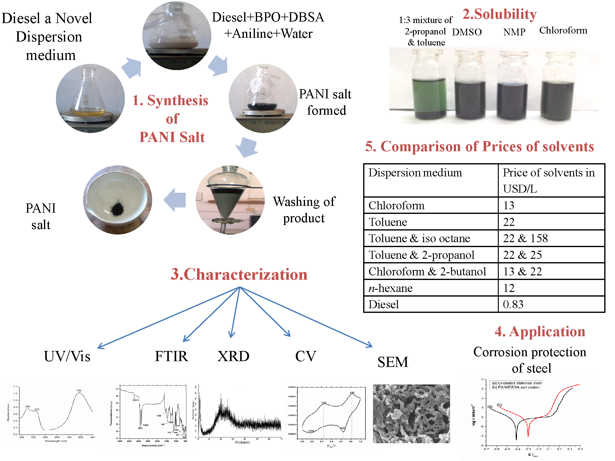
Article

Cost Effective Chemical Oxidative Synthesis of Soluble and Electroactive Polyaniline Salt and Its Application as Anticorrosive Agent for Steel

1
Institute of Chemical Sciences, University of Peshawar, Peshawar 25120, Pakistan
2
NationalCentre of Excellence in Physical Chemistry, University of Peshawar, Peshawar 25120, Pakistan
3
TU Braunschweig Institute of Energy and Process Systems Engineering, Franz-Liszt-Straße 35, 38106 Braunschweig, Germany
*
Author to whom correspondence should be addressed.
Materials 2019, 12(9), 1527; https://doi.org/10.3390/ma12091527
Submission received: 16 April 2019 / Revised: 1 May 2019 / Accepted: 7 May 2019 / Published: 10 May 2019
(This article belongs to the Special Issue The Application of Electroactive Polymers)

Abstract

:
The cost effective synthesis of electroactive polyaniline (PANI) while retaining its desirable properties is one of the most debatable and challenging tasks for researchers in the field. Herein, we report a cost effective inverse emulsion polymerization pathway for the synthesis of soluble and processable PANI salt by using diesel as a novel dispersion medium. Different reaction parameters and their effects on the properties and yield of polyaniline were optimized. The polymer exhibited a highly porous morphology and was found to be stable up to 417 °C. The PANI salt showed good solubility in common solvents, such as chloroform, N-Methyl-2-pyrrolidone (NMP), dimethyl sulphoxide (DMSO) and in a 1:3 mixtures by volume of 2-propanol and toluene. The coating of the synthesized PANI salt on stainless steel has shown good corrosion resistant behavior in marine water by reducing the corrosion rate to 67.9% as compared to uncoated stainless steel.

Graphical Abstract

1. Introduction

Polyaniline (PANI) has been under intense investigation for the last few decades [1], in its different redox states, including pernigraniline, lecuemeraldine, emeraldine base and emeraldine salt. It has been synthesized by different methods including electrochemical [2], chemical oxidative [3] including emulsion [4], and inverse emulsion polymerization techniques [5]. Among these, inverse emulsion polymerization is reported to be more effective because PANI obtained by this method possesses enhanced conductivity [6], solubility in common organic solvents [7], thermal stability, and good processability [8].
The properties of the final product considerably rely on different reaction parameters such as the type of oxidant, dopant, non-aqueous phase and vice versa. Particular attention has been paid to the type of organic phase by employing different types of organic dispersion media. Table 1 shows the effects of employing different dispersion media on the properties of PANI. PANI-bearing composites, having good electrical conductivity and good mechanical properties, were synthesized through inverse emulsion polymerization using a toluene and iso-octane mixture as the dispersion medium [9]. Rao, P.S. et al. used chloroform as the dispersion medium and benzoyl peroxide as the oxidant and obtained a thermally stable and soluble PANI [6].
A mixture of toluene and 2-propanol, was used by Shreepathi, S. and Holze, R. for polymerization of aniline, soluble in chloroform, 2:1 mixture of toluene and 2-propanol, NMP and dichloromethane [7,10]. Later on, pure toluene was used as a dispersion medium but the solubility was reduced [11]. Bang et al. synthesized highly bolometric Near Infra Red (NIR) sensitive PANI composites with carbon nanotubes in hydrochloric acid media [12]. Similarly, Sun et al. [13], have used perchloric acid as a medium for the fabrication of PANI nanofibers coated with platinum for applications in fuel cells. The synthesis of PANI/DBSA salt using a DBSA-CTAB mixture as surfactant and toluene as a dispersion media was reported by Calheiros et al. [14]. The synthesized materials were reported to have good electrical conductivity and effectiveness at electromagnetic interference shielding.
Several other methods using different media have been employed to obtain processable and soluble PANI for various applications but the main problem of production costs associated with these methods, particularly in terms of dispersion mediums, persists. For example the cost of the commonly used but not easily available dispersion mediums such as chloroform (13 USD/L), 2-propanol (25 USD/L), 2-butanol (22 USD/L), toluene (22 USD/L), n-hexane (12 USD/L) and iso-octane (158 USD/L) makes the production of PANI a difficult task from commercial point of view. In recent years, we have reported sophisticated methodologies for the synthesis of PANI salts with desirable properties [4,15]. Herein, as further improvement, we report a cost effective and facile synthetic route for the synthesis of PANI salt with improved solubility, good electrochemical activity and excellent corrosion protection ability by using diesel (0.83 USD/L) as a cost effective and novel dispersion media. It can be observed from Table 1 that the use of diesel can not only reduce the cost of production, but also that the synthesized polyaniline exhibits superior properties.

2. Material and Methods

2.1. Materials

Analytical grade aniline (Acros organic, Morris, NJ, USA) was double distilled under vacuum and stored under a cold environment. Commercial diesel obtained from Pakistan State Oil (PSO), as a complex mixture of hydrocarbons with carbon numbers in the range C9 and higher, having boiling range 160 to 366 °C, specific gravity of 0.828 and viscosity 3.11 cst at 20 °C, was used as received. Other chemicals like benzoyl peroxide (BPO) (Merck, Kenilworth, NJ, USA), dodecylebenzensulphonic acid (DBSA) (Acros organic, Morris, NJ, USA) and acetone (Sigma Aldrich, St. Louis, MO, USA) were also used as received. Ultra pure (Millipore, Burlington, MA, USA) and natural water of Indian Ocean having an average of 3.5% salinity were used, respectively, for solution preparation and corrosion studies.

2.2. Synthesis of Polyaniline Salt

The Polyaniline salt was synthesized following an inverse emulsion polymerization protocol [18]. In a typical experiment 30 mL of diesel, employed as a novel dispersion medium, was taken in a round bottom flask and 2.9 mmol of benzoyl peroxide was added to it followed by addition of 1.5 mmol DBSA and 2.2 mmol of aniline. A white milky emulsion was formed by addition of 30 mL of distilled water to this reaction mixture. The reaction mixture was kept on stirring for 24 h at room temperature. Afterwards, the mixture was put into a separating funnel and 30 mL acetone was added to it. Organic and inorganic phases were separated. Organic phase containing PANI was washed with distilled water several times. After washing with water, 30 mL acetone was added to it in order to break emulsion and green colored PANI was precipitated at the bottom. Then PANI was washed with acetone several times and the obtained product was dried in oven at 60 °C for 4 h.

2.3. Optimization

A number of reactions were carried in the same manner but varying different reaction parameters in order to check the effect of monomer, DBSA, oxidant and solvent on the properties and percentage yield of PANI. The product obtained was further processed for characterization and applications. Different samples synthesized with varying amounts of monomer, dopant, oxidant, and solvents were coded as mentioned in Table 2, Table 3, Table 4 and Table 5. Percentage yield in terms of aniline concentration was calculated by using the following formula [4].
%   yield   of   PANI = Weight   of   PANI Weight   of   aniline × 100

2.4. Characterization

Since it is important to know about the properties of a material before subjecting it to some applications, different tools were utilized to characterize the synthesized PANI.
UV/Visible spectra of samples were recorded in chloroform in the range of 300–900 nm by using a Perkin Elmer (Buckinghamshire, UK) spectrophotometer.
Fourier-transform infrared spectroscopy (FTIR) analysis of powder PANI salt was carried out in the range of 400–4000 cm−1 by using a IRAffinity-1S Shimadzu Fourier Transform Infrared Spectrophotometer (Shimadzu, Tokyo, Japan). XRD (X-ray diffractometer) patterns of PANI were achieved by using Cu Kα radiations (λ = 1.5405 Å) JEOL JDX-3532 (JEOL, Tokyo, Japan). SEM micrographs were taken by using a JSM-6490 (JEOL, Tokyo, Japan) electron microscope. Thermal stability of PANI samples were determined by using Perkin Elmer, Diamond series (Waltham, MA, USA) at heat rate of 10 °C/min under nitrogen atmosphere. Electrochemical properties were studied by ALS/DY 2323 Biopotentiostate (ALS, Tokyo, Japan). Cyclic voltammograms were recorded in a glass cell containing three electrode assembly and 0.5 M H2SO4. PANI salt was dip-coated onto a gold sheet working electrode. Optimum care was made to make sure that every time same amount of polymer is loaded on the electrode. For this purpose, 5.8% PANI salt solutions were always prepared in mixture of chloroform and 2-propanol and gold sheet electrode was dipped into it for one minute. Saturated calomel electrode (SCE) and another gold sheet served as reference electrodes and counter electrode, respectively. Corrosion studies were performed by using Reference 3000 Zero Resistance Ammeter (ZRA) potentiostat/galvanostat (Gamry, Warminster, PA, USA).

2.5. Application

Selected PANI salts samples were tested for their corrosion protection ability for stainless steel electrode against SCE in water samples from Indian Ocean. Prior to this experiment, the disc of stainless steel was thoroughly polished with an abrasive paper and washed with acetone, followed by ethanol and water in order to remove any soluble impurities. Due to the physical shape of the steel disc electrode, polymer loading was done through drop coating. PANI solution was prepared in the manner mentioned above for gold sheet electrode and a clear glass rod was dipped in the solution and used to put a drop on disc electrode. After putting only one drop the solvent was allowed to evaporate leaving PANI salt in the form of a smooth thin layer on electrode.
After drying, the working electrode was transferred to the three electrode cell containing water sample from the Indian Ocean. Tafel plot was plotted using ZRA potentiostat/galvanostat Reference 3000 Gamry (USA). DC105 DC corrosion software was used for this study. Potentiodynamic current density measurements were performed at 25 °C by scanning the potential from −400 mV to +400 mV at a scan rate of 3 mV/s. Corrosion current (icorr), corrosion potential (Ecorr), βA, βC and corrosion rate (CR, mm/year) was determined by extrapolation of Tafel plot. The experiments were carried out under the same conditions in triplicate for each sample. In order to see the effect of film thickness on corrosion protection performance, PANI films with different number of drops coated on the electrode were studied.

3. Results and Discussion

3.1. Effect of Different Parameters on % Yield

The % yield of PANI salt was found to be greatly affected by changing different parameters like amount of monomer, oxidant, dopant and solvents. Additional details are given below.

3.1.1. Effect of Amount of Monomer

Figure 1a shows the % yield of PANI in terms of amount of aniline in the feed. At a very small amount of aniline, no formation of the PANI occurred and instead some oligomers were formed. The maximum yield was obtained at 2.20 mmol of aniline in the reaction mixture, beyond this a decrease in the % yield of reaction was observed, which can be attributed to the high monomer to oxidant ratio that caused a decrease in the efficiency of the oxidant [19] (Table 2). The sample with maximum yield was labeled as PANI A4.

3.1.2. Effect of Amount of Oxidant

Figure 1b shows the effect of amount of oxidant on the % yield of PANI. At a very low amount of oxidant (0.21 mmol) no polymerization of aniline occurs, presuming that this amount was not sufficient to initiate the oxidation of aniline monomer. Increasing the amount of oxidant causes a gradual increase in the % yield of PANI and maximum yield was obtained at 2.90 mmol of oxidant, after which there was a decrease in the % yield as shown in Table 3. The % yield was found to decrease after a further increase in the amount of oxidant, which could be attributed to the production of excess of radical cations which may result in shorter polymer chain called oligomers. These oligomers were soluble in acetone and removed from the PANI product during the washing [20]. The sample having maximum yield was labeled as PANI B9.

3.1.3. Effect of Amount of Dopant

The effect of amount of dopant on the % yield of PANI is shown in Figure 1c. An increase of % yield was observed when the amount of DBSA was changed from 0.91 mmol to 1.52 mmol which could be due to the insertion of more DBSA into polymer chain, hence increasing its weight. The sample with maximum yield was named as PANI D2. After 1.52 mmol there was a decrease in the yield which may be due to the formation of more micelle having limited number of monomer particles, which results in limited growth of the polymer chain. As a result, small chain polymer formation occurs. This product was soluble in acetone and removed during washing [21]. The filtrate was further analyzed using UV/Visible spectroscopy. The UV/visible spectrum of filtrate is given in Figure 1e. The appearance of peaks in 445 and 279 nm regions supported the formation of oligomers [22,23].

3.1.4. Effect of Amounts of Solvents

Figure 1d shows the effect of amounts of solvents (diesel and water) on the % yield of PANI. The quantity of both the solvents was varied from 10 mL to 50 mL and maximum yield was obtained for 1:1 ratio (30 mL diesel and 30 mL water). The sample obtained at 1:1 ratio of solvents was labeled as PANI S3. Increasing the amount of water as inorganic phase did not favor the inverse emulsion polymerization [10], whereas a further increase in the amount of diesel could reduce the chances of collision between monomer and oxidant particles to produce PANI due to the denser nature of diesel.
After optimizing all the reaction conditions necessary for the synthesis, an experiment was conducted in which all optimized conditions were applied and the polymer obtained was labeled as PANI salt.

3.2. Solubility of the Polymer

The solubility of PANI salt was checked in different common solvents and was found to be soluble in chloroform, NMP, DMSO and in a 1:3 mixture by volume of 2-propanol and toluene. Better solubility (5.8%) was observed in chloroform. The solubility of PANI in NMP and DMSO can be attributed to the polar nature of these solvents while solubility in chloroform might be due to the fact that the attachments of three electronegative chlorine atoms to carbon makes hydrogen more electropositive which in turn form a hydrogen bond with PANI [4]. The PANI salt was insoluble in pure ethanol, 2-propanol, and toluene but was soluble in 1:3 mixture of 2-propanol and toluene, which may be due to presence of polar and non polar end in 2-propanol. Perhaps the non polar end of 2-propanol interacts with the non polar toluene resulting in a big non polar group which in turn interacts with long non polar alkyl group of DBSA while the polar end of 2-propanol form hydrogen bonds with PANI [24]. The appearance of green color in chloroform and 1:3 mixture of 2-propanol and toluene confirms the doping of DBSA into PANI. The blue color of other PANI solutions suggests its transformation to the base form. This behavior could be due to the solvatochromic effect of PANI and its interaction with solvents characterized by different polarity. Solvatochromism is the property of a chemical substance to change color with the change of solvent polarity. The solvatochromic shift of a chromophore reflects a strong relation between solvent polarity with the absorption and emission spectra [25,26]. The solutions of PANI in different solvents are shown in Figure 2.

3.3. UV/Visible Spectroscopy

The doping effect of DBSA on PANI was investigated through UV/Visible spectroscopic analysis, where chloroform is used as a solvent. The UV/Visible spectra of PANI salts, having different concentrations of monomer, oxidant, dopant and solvent are given in Figure 3a–d, respectively. All the samples give rise to three characteristics absorption bands, with slight variation in the band position, in the range of 341–349, 411–417, and 761–800 nm, which correspond, respectively, to π–π* transition of the benzenoid ring, polaron-π* transition of the quinoid ring and π-polaron transition [16,27,28].
The differences in the peak positions and intensities in the UV/Visible spectra of these samples might be a consequence of the extent of doping and different conjugation length of polymer chains [11,15,29].
For ready comparison, the UV/Visible spectra of selected samples synthesized with varying amounts of monomer, oxidant, DBSA and solvent are shown in Figure 4. From these spectra it is indicated that PANI has been successfully prepared in the salt form. The presence of two peaks in the visible region for all samples indicates that the samples are collected in the doped form [8]. PANI A4, PANI B9, PANI D2, and PANI S3 showed almost same UV/Visible spectra, however, a blue shift can be seen in the red region peak of PANI B9. This might be due to over oxidation of aniline due to presence of more oxidant units which resulted in shorter polymer chain. Due to smaller chain formation, steric hindrance between dopant and polymer chain increases and hence transition may become difficult [30].
The UV/Visible spectrum of optimized PANI salt (Figure 5) exhibit all featured characteristics of good quality PANI.

3.4. Extent of Doping

The extent of doping was calculated from the UV/Visible absorption spectra and is shown in Table 6. The level of doping is the ratio between exciton (π-polaron transition)/benzenoid (π–π* transition) [17]. A very slight difference has been observed in the extent of doping for different samples synthesized at different conditions. These results suggest that the extent of doping into PANI chain is not influenced by changing the amounts of monomer, dopant and solvent, however PANI B9 shows lower level of doping which might be a result of over oxidation of PANI due to more oxidant providing less chance to the dopant to enter into a polymer chain [31].

3.5. FTIR Spectroscopy

The FTIR spectra of different PANI samples, i.e., PANI A4, PANI B9, PANI D2 and PANI S3 are shown in Figure 6, where as the FTIR spectra of the PANI salt is shown in Figure 7. The peak positions of PANI along with their assignment are given in Table 7, where the 503 and 573 cm−1 band can be assigned to the absorption of –SO3H and SO3−1 [16,18].
The peak at 798 cm−1 represents the C-H bending vibrations [20], 1002 cm−1 is because of the absorption of –SO3H which is a prominent peak in all these samples [32]. The presence of bands at 503, 573 and 1002 cm−1 indicate the presence of DBSA. The peak at 1122 cm−1 is due to the in-plane bending vibration of C–H [33], while the 1298 cm−1 is because of C–N stretching of the benzenoid ring of PANI [34]. The band at 1467 cm−1 and 1565 cm−1 are assigned to benzenoid and quinoid ring vibration [14]. The presence of a peak at 3232 cm−1 confirmed the presence of N–H and NH2, which give rise to symmetric and asymmetric stretching [6]. The C–H stretching vibrations of the aromatic aniline ring are observed in the range of 2853 and 2916 cm−1 [8]. The appearance of all these typical peaks of PANI and DBSA provides the evidence for formation of PANI doped with DBSA.

3.6. X-Ray Diffraction Analysis

The X-ray diffraction (XRD) technique is used to find the crystallinity of polymers in both the microcrystal and powder form. The XRD patterns of PANI A4, PANI B9, PANI D2, PANI S3 are given in Figure 8a–d, respectively, and that of PANI salt is presented in Figure 9. All these samples show a sharp peak at 25° and a broad peak at 19°, which are the characteristic peaks of PANI [35] The broad peak at 19° shows the amorphous nature of PANI which has strong correlation with the already reported one [15]. This peak clarifies the doping of polymer with DBSA. The intense peak at 25° indicates the presence of polymer crystallinity, which is due to the Vander Waal’s distance among the stacks of phenylene ring of PANI chain [9]. The crystallinity of PANI, due to repetition of quinoid and benzenoid rings in the polymer chain [36] leads to high conductivity of PANI salt.

3.7. Cyclic Voltammetry

The redox nature of PANI salt was investigated through cyclic voltammetry, using gold as a working electrode in a potential range of −0.2 to 0.9 V, scan rate of 50 mV/s in supporting electrolyte of 0.5 M H2SO4. The cyclic voltammograms registered for PANI A4, PANI B9, PANI D2, PANI S3 and PANI salt are shown in Figure 10 and Figure 11. These cyclic voltammograms indicate that almost all samples have four peaks and two redox pairs. The first peak at around ESCE = 0.18 to 0.23 V is due to the conversion of neutral leucoemeraldine form to partially oxidized emeraldine form of PANI. This peak is shifted to 0.37 V in the PANI S3 sample. The peak at around ESCE = 0.77 to 0.82 V for all these samples can be assigned to the conversion of emeraldine to pernigraniline state of PANI. This peak has been shifted to 0.70 V in the PANI S3 sample. The shifting of these redox peaks may be due to the high doping level of DBSA content. Doping has a direct relation with conductance of polymer to some extent but beyond 50% doping, the excess of a long chain dopant such as DBSA causes steric hindrance. Consequently the interaction of PANI chain with DBSA decreases, which reduces the delocalization of π electrons and hence results in a low charge transfer [17]. In the reverse process, the peak at around ESCE = 0.64 to 0.54V show the conversion of pernigraniline to emeraldine form of PANI. Similarly, the appearance of peaks at ESCE = −0.007 V, 0.023 V, 0.0011 V, −0.0071V, and −0.035 V show the conversion of emeraldine form of PANI back to the fully reduced leucoemeraldine [35]. All these discrete peaks represent good electroactivity and reversibility of the material.

3.8. Application of the Synthesized PANI in Corrosion Protection of Steel

Literature studies reveal that electrochemically synthesized PANI has better corrosion protection ability when coated on metal surface in acidic media but fails to do so in saline media [32,37]. Rout, T.K. et al. used a formulated blend with polyaniline as a corrosion protecting material of steel and that reduced the corrosion of steel up to 3.5 mm/year, however due to lower solubility they used different materials for making blend which makes this material very expensive from an economic point of view [38].
Chemically synthesized PANI has also been used as a corrosion protective material for stainless steel [9].
Keeping in mind the usefulness of PANI for corrosion protection of steel, the samples synthesized in present study were also tested for their corrosion protection ability. The Tafel plots of uncoated stainless steel and PANI A4, PANI B9, PANI D2 and PANI S3 coated stainless steel are shown in the Figure 12a. The corresponding values of icorr, Ecorr and corrosion rate per year is shown in the Table 8. The Tafel plot of each optimized sample vs uncoated stainless steel shows corrosion protection on stainless steel in water samples from the Indian Ocean. The Indian Ocean has an average of 3.5% salinity, mostly due to NaCl. Generally the ocean environment is considered as a complex chemical system where the environment is more aggressive and corrosive than the laboratory prepared electrolytes. It possesses salinity, complex biological activity, a number of minor ions, pollutants and so on. However, it is the salinity which is considered as the major cause of corrosion in oceans. Yet it is not uniform even in the same ocean and there might be different ions content at different places. Generally, these ions of the dissolved salts, which mainly consist of NaCl, play a very important role in corrosion by covering the steel surface with insoluble products and enhancing passivation of the surface [39,40].
From the Table 8 it can be observed that among all samples of PANI the PANI B9 sample shows a remarkable positive potential shift and reduction in icorr value as compared to uncoated stainless steel. The corrosion rate of uncoated stainless steel is 4.906 CR mm/year and that of PANI B9 is 1.575 CR mm/year showing that PANI coating on stainless steel has greatly reduced the corrosion of steel.
Figure 13 shows the Tafel plot of PANI salt coated stainless steel vs uncoated stainless steel, and the corresponding icorr, Ecorr and CR mm/year is shown in the Table 8. From the Table 8 it is clear that the values of icorr, Ecorr and CR for uncoated stainless steel are 10.70 µA, −467.0 mV and 4.906 mm/year, respectively while for PANI salt coated stainless steel these values are 0.859 µA, −295.0 mV and 0.3927 mm/year, which indicate a remarkable positive shift in potential, great reduction in icorr value and greater decrease in corrosion rate. These results indicate that diesel can effectively be used in the synthesis of efficient and cost effective corrosion protection coating.
Tafel polarization of single layered coating (Single drop coating) have been checked and compared with Tafel plots of many layered coatings (double and triple), as shown in the Figure 12b. A negligible difference in corrosion has been observed among single layered, doubled and tripled layered. However, it was found that sticking power of polymer was reduced in many layered coating as compared to a single layer.

3.9. Morphology of PANI

The morphology of PANI salt was studied at different magnification and is presented in Figure 14 and Figure 15. The images show that PANI salt has a cauliflower like morphology, having good porosity [17]. The appearance of porosity in all micrographs make the PANI salt a good corrosion inhibiting material having self healing ability due to presence of pores [41]. The material can also be used effectively for the immobilization of bio components.

3.10. Thermogravimeteric Analysis

Kinetics of thermal decomposition along with the quantity of dopant inserted in the polymer structural backbone is determined by thermogravimetric analysis (TGA). The thermograms of different samples of PANI are shown in Figure 16 and Figure 17. The sample was kept at 50 °C for one minute and then subjected to heat at the rate of 10 °C/min. The TGA curves shows that PANI A4 is thermally stable up to 305 °C, PANI D2 up to 293 °C, PANI B9 PANI up to 299 °C, PANI S3 PANI up to 300 °C and PANI salt up to 417 °C. The thermogram of PANI salt shows a three-step degradation pattern. The first weight loss occurs up to 293 °C which can be attributed to unbound moisture because PANI salt dried at vacuum still absorbs moisture due to its hygroscopic nature [2]. The second weight loss occurs at the range of 290–417 °C, which corresponds to the loss of dopant [28]. After 417 °C, the loss in weight occurs in a continuous way, which is due to the structural degradation of PANI backbone [42].

4. Conclusions

In conclusion, diesel can be effectively utilized for the cost effective synthesis of highly porous, soluble, thermally stable and anticorrosive polyaniline. The synthesized polymer retains all the good properties of PANI salt and hence make it a potential candidate for various technological applications. The cost of synthesis of PANI salt with improved solubility, thermal stability and good corrosion protection ability has been reduced to approximately 96% using diesel as a solvent instead of commonly used organic solvents.

Author Contributions

A.-u.-H.A.S. conceptualized the project and contributed in writing, editing. M.K. performed the experimental work, formal analysis and contributed in writing. R.U. contributed in formal analysis. S.B. contributed in conceptualizing, writing, correction and editing of the manuscript.

Funding

This research received no external funding.

Acknowledgments

We acknowledge support by the German Research Foundation and the Open Access Publication Funds of the Technische Universität Braunschweig. Support from Alexander von Humboldt Foundation Germany is also gratefully acknowledged.

Conflicts of Interest

There are no conflicts of interest.

References

  1. Letheby, H. XXIX.—On the production of a blue substance by the electrolysis of sulphate of aniline. J. Chem. Soc. 1862, 15, 161–163. [Google Scholar] [CrossRef]
  2. Ziadan, K.M.; Saadon, W.T. Study of the electrical characteristics of polyaniline prepeared by electrochemical polymerization. Energy Procedia 2012, 19, 71–79. [Google Scholar] [CrossRef]
  3. Kamran, M.; Ullah, H.; Anwar-ul-Haq, A.S.; Bilal, S.; Tahir, A.A.; Ayub, K. Combined experimental and theoretical study of poly (aniline-co-pyrrole) oligomer. Polymer 2015, 72, 30–39. [Google Scholar] [CrossRef]
  4. Bilal, S.; Gul, S.; Holze, R.; Anwar-ul-Haq, A.S. An impressive emulsion polymerization route for the synthesis of highly soluble and conducting polyaniline salts. Synth. Met. 2015, 206, 131–144. [Google Scholar] [CrossRef]
  5. Bhadra, S.; Khastgir, D.; Singha, N.K.; Lee, J.H. Progress in preparation, processing and applications of polyaniline. Prog. Polym. Sci. 2009, 34, 783–810. [Google Scholar] [CrossRef]
  6. Rao, P.S.; Sathyanarayana, D.N.; Palaniappan, S. Polymerization of Aniline in an Organic Peroxide System by the Inverted Emulsion Process. Macromolecules 2002, 35, 4988–4996. [Google Scholar] [CrossRef] [Green Version]
  7. Shreepathi, S.; Holze, R. Spectroelectrochemical investigations of soluble polyaniline synthesized via new inverse emulsion pathway. Chem. Mater. 2005, 17, 4078–4085. [Google Scholar] [CrossRef]
  8. Yang, J.; Ding, Y.; Chen, G.; Li, C. Synthesis of conducting polyaniline using novel anionic Gemini surfactant as micellar stabilizer. Eur. Polym. J. 2007, 43, 3337–3343. [Google Scholar] [CrossRef]
  9. Ruckenstein, E.; Sun, Y. Polyaniline-containing electrical conductive composite prepared by two inverted emulsion pathways. Synth. Met. 1995, 74, 107–113. [Google Scholar] [CrossRef]
  10. Ullah, R.; Bilal, S.; Ali, K.; Anwar-ul-Haq, A.S. Synthesis and characterization of polyaniline doped with Cu II chloride by inverse emulsion polymerization. Synth. Met. 2014, 198, 113–117. [Google Scholar] [CrossRef]
  11. Kim, J.; Kwon, S.; Ihm, D. Synthesis and characterization of organic soluble polyaniline prepared by one-step emulsion polymerization. Current Applied Physics 2007, 7, 205–210. [Google Scholar] [CrossRef]
  12. Bang, D.; Lee, J.; Park, J.; Choi, J.; Chang, Y.W.; Yoo, K.-H.; Huh, Y.-M.; Haam, S. Effectively enhanced sensitivity of a polyaniline-carbon nanotube composite thin film bolometric near-infrared sensor. J. Mater. Chem. 2012, 22, 3215–3219. [Google Scholar] [CrossRef]
  13. Sun, R.; Xia, Z.; Shang, L.; Fu, X.; Li, H.; Wang, S.; Sun, G. Hierarchically ordered arrays with platinum coated PANI nanowires for highly efficient fuel cell electrodes. J. Mater. Chem. A. 2017, 5, 15260–15265. [Google Scholar] [CrossRef]
  14. Calheiros, L.F.; Soares, B.G.; Barra, G.M.O. DBSA-CTAB mixture as the surfactant system for the one step inverse emulsion polymerization of aniline: Characterization and blend with epoxy resin. Synth. Met. 2017, 226, 139–147. [Google Scholar] [CrossRef]
  15. He, C.; Tan, Y.; Li, Y. Conducting polyaniline nanofiber networks prepared by the doping induction of camphor sulfonic acid. J. Appl. Polym. Sci. 2003, 87, 1537–1540. [Google Scholar] [CrossRef]
  16. Rao, P.S.; Subrahmanya, S.; Sathyanarayana, D. Inverse emulsion polymerization: a new route for the synthesis of conducting polyaniline. Synth. Met. 2002, 128, 311–316. [Google Scholar] [CrossRef]
  17. Han, Y.G.; Kusunose, T.; Sekino, T. One-step reverse micelle polymerization of organic dispersible polyaniline nanoparticles. Synth. Met. 2009, 159, 123–131. [Google Scholar] [CrossRef]
  18. Bilal, S.; Gul, S.; Ali, K.; Anwar-ul-Haq, A.S. Synthesis and characterization of completely soluble and highly thermally stable PANI-DBSA salts. Synth. Met. 2012, 162, 2259–2266. [Google Scholar] [CrossRef]
  19. Dan, A.; Sengupta, P. Synthesis and characterization of polyaniline prepared in formic acid medium. J. Appl. Polym. Sci. 2004, 91, 991–999. [Google Scholar] [CrossRef]
  20. Weng, S.; Lin, Z.; Chen, L.; Zhou, J. Electrochemical synthesis and optical properties of helical polyaniline nanofibers. Electrochim. Acta 2010, 55, 2727–2733. [Google Scholar] [CrossRef]
  21. Dai, L.; Xu, Y.; Gal, J.Y.; Lu, X.; Wu, H. m-Chloroaniline emulsion polymerization, macromolecular chain structure and electrochemical properties. Polym. Int. 2002, 51, 547–554. [Google Scholar] [CrossRef]
  22. Shumakovich, G.P.; Otrokhov, G.V.; Khlupova, M.E.; Vasil’eva, I.S.; Zaitseva, E.A.; Morozova, O.V.; Yaropolov, A.I. Laccase-catalyzed synthesis of aniline oligomers and their application for the protection of copper against corrosion. RSC Adv. 2014, 4, 30193–30196. [Google Scholar] [CrossRef]
  23. Yadav, D.K.; Chauhan, D.; Ahamad, I.; Quraishi, M. Electrochemical behavior of steel/acid interface: adsorption and inhibition effect of oligomeric aniline. RSC Adv. 2013, 3, 632–646. [Google Scholar] [CrossRef]
  24. Pawar, S.; Patil, S.; Chougule, M.; Achary, S.; Patil, V. Microstructural and optoelectronic studies on polyaniline: TiO2 nanocomposites. Int. J. Polymer. Mater. 2010, 60, 244–254. [Google Scholar] [CrossRef]
  25. Sabatini, V.; Pifferi, V.; Checchia, S.; Rebeccani, S.; Farina, H.; Ortenzi, M.; Falciola, L. A Combined XRD, Solvatochromic, and Cyclic Voltammetric Study of Poly (3,4-Ethylenedioxythiophene) Doped with Sulfonated Polyarylethersulfones. Towards New Conduct. Polym. 2018, 10, 770. [Google Scholar] [CrossRef]
  26. Roncali, J. Conjugated poly(thiophenes): synthesis, functionalization, and applications. Chem. Rev. 1992, 92, 711–738. [Google Scholar] [CrossRef]
  27. Cao, Y.; Qiu, J.; Smith, P. Effect of solvents and co-solvents on the processibility of polyaniline: I. solubility and conductivity studies. Synth. Met. 1995, 69, 187–190. [Google Scholar] [CrossRef]
  28. Rao, P.S.; Sathyanarayana, D.N. Inverted emulsion cast electrically conducting polyaniline–polystyrene blends. J. Appl. Polym. Sci. 2002, 86, 1163–1171. [Google Scholar] [CrossRef]
  29. Wang, Y.; Jing, X. Effect of solution concentration on the UV–vis spectroscopy measured oxidation state of polyaniline base. Polym. Test. 2005, 24, 153–156. [Google Scholar] [CrossRef]
  30. Shao, L.; Qiu, J.; Liu, M.; Feng, H.; Zhang, G.; Lu, S.; Qin, L. Preparation and characterization of attapulgite/polyaniline nanofibers via self-assembling and graft polymerization. Chem. Eng. J. 2010, 161, 301–307. [Google Scholar] [CrossRef]
  31. Blaha, M.; Trchova, M.; Bober, P.; Morávkova, Z.; Prokes, J.; Stejskal, J. Polyaniline: Aniline oxidation with strong and weak oxidants under various acidity. Mater. Chem. Phys. 2017, 194, 206–218. [Google Scholar] [CrossRef]
  32. Abdiryim, T.; Jamal, R.; Nurulla, I. Doping effect of organic sulphonic acids on the solid state synthesized polyaniline. J. Appl. Polym. Sci. 2007, 105, 576–584. [Google Scholar] [CrossRef]
  33. Sathiyanarayanan, S.; Devi, S.; Venkatachari, G. Corrosion protection of stainless steel by electropolymerised pani coating. Prog. Org. Coat. 2006, 56, 114–119. [Google Scholar] [CrossRef]
  34. Shahabuddin, S.; Sarih, N.; Afzal Kamboh, M.; Rashidi Nodeh, H.; Mohamad, S. Synthesis of polyaniline-coated graphene oxide@ SrTiO3 nanocube nanocomposites for enhanced removal of carcinogenic dyes from aqueous solution. Polymers 2016, 8, 305. [Google Scholar] [CrossRef] [PubMed]
  35. Ullah, R.; Bilal, S.; Ali, K.; Alakhras, F. Synthesis and characterization of polyaniline doped with polyvinyl alcohol by inverse emulsion polymerization. Synth. Met. 2016, 222, 162–169. [Google Scholar] [CrossRef]
  36. Sharma, B.K.; Gupta, A.K.; Khare, N.; Dhawan, S.K.; Gupta, H.C. Synthesis and characterization of polyaniline–ZnO composite and its dielectric behavior. Synth. Met. 2009, 159, 391–395. [Google Scholar] [CrossRef]
  37. Wessling, B.; Posdorfer, J. Corrosion prevention with an organic metal (polyaniline): corrosion test results. Electrochim. Acta 1999, 44, 2139–2147. [Google Scholar] [CrossRef]
  38. Rout, T.K.; Jha, G.; Singh, A.K.; Bandyopadhyay, N.; Mohanty, O.N. Development of conducting polyaniline coating: a novel approach to superior corrosion resistance. Surf. Coat. Technol. 2003, 167, 16–24. [Google Scholar] [CrossRef]
  39. El-Shazly, A.; Al-Turaif, H. Improving the corrosion resistance of buried steel by using polyaniline coating. Int. J. Electrochem. Sci 2012, 7, 211–221. [Google Scholar]
  40. Ahmad, N.; MacDiarmid, A.G. Inhibition of corrosion of steels with the exploitation of conducting polymers. Synth. Met. 1996, 78, 103–110. [Google Scholar] [CrossRef]
  41. Yabuki, A.; Nishisaka, T. Self-healing capability of porous polymer film with corrosion inhibitor inserted for corrosion protection. Corros. Sci. 2011, 53, 4118–4123. [Google Scholar] [CrossRef]
  42. Wang, Y.; Yu, H.; Li, Y.; Wang, T.; Xu, T.; Chen, J.; Fan, Z.; Wang, Y.; Wang, B. Facile Preparation of Highly Conductive Poly (amide-imide) Composite Films beyond 1000 S m−1 through Ternary Blend Strategy. Polymers 2019, 11, 546. [Google Scholar] [CrossRef]
Figure 1. Effect of different reaction parameters on % yield of PANI (a) Amount of monomer, (b) Amount of Oxidant, (c) Amount of dopant in mmol, (d) Amount of solvent in mL, and (e) UV/Visible spectrum filtrate from product washing indicating the presence of oligomers.
Materials 12 01527 g001
Figure 2. Solutions of PANI salt in different solvents as indicated.
Materials 12 01527 g002
Figure 3. UV/Visible Spectra of different PANI samples indicated in Table 1, Table 2, Table 3 and Table 4. (a) Monomer optimized samples (b) Oxidant optimized samples (c) DBSA optimized samples (d) Solvents optimized samples.
Materials 12 01527 g003
Figure 4. UV/Visible spectra of PANI A4, PANI D2, PANI B9 and PANI S3.
Materials 12 01527 g004
Figure 5. UV/Visible spectrum of PANI salt.
Materials 12 01527 g005
Figure 6. FTIR spectrum of different PANI samples as indicated.
Materials 12 01527 g006
Figure 7. FTIR spectrum of PANI salt.
Materials 12 01527 g007
Figure 8. X-ray diffractograms of (a) PANI A4 (b) PANI B9 (c) PANI D2 (d) PANI S3.
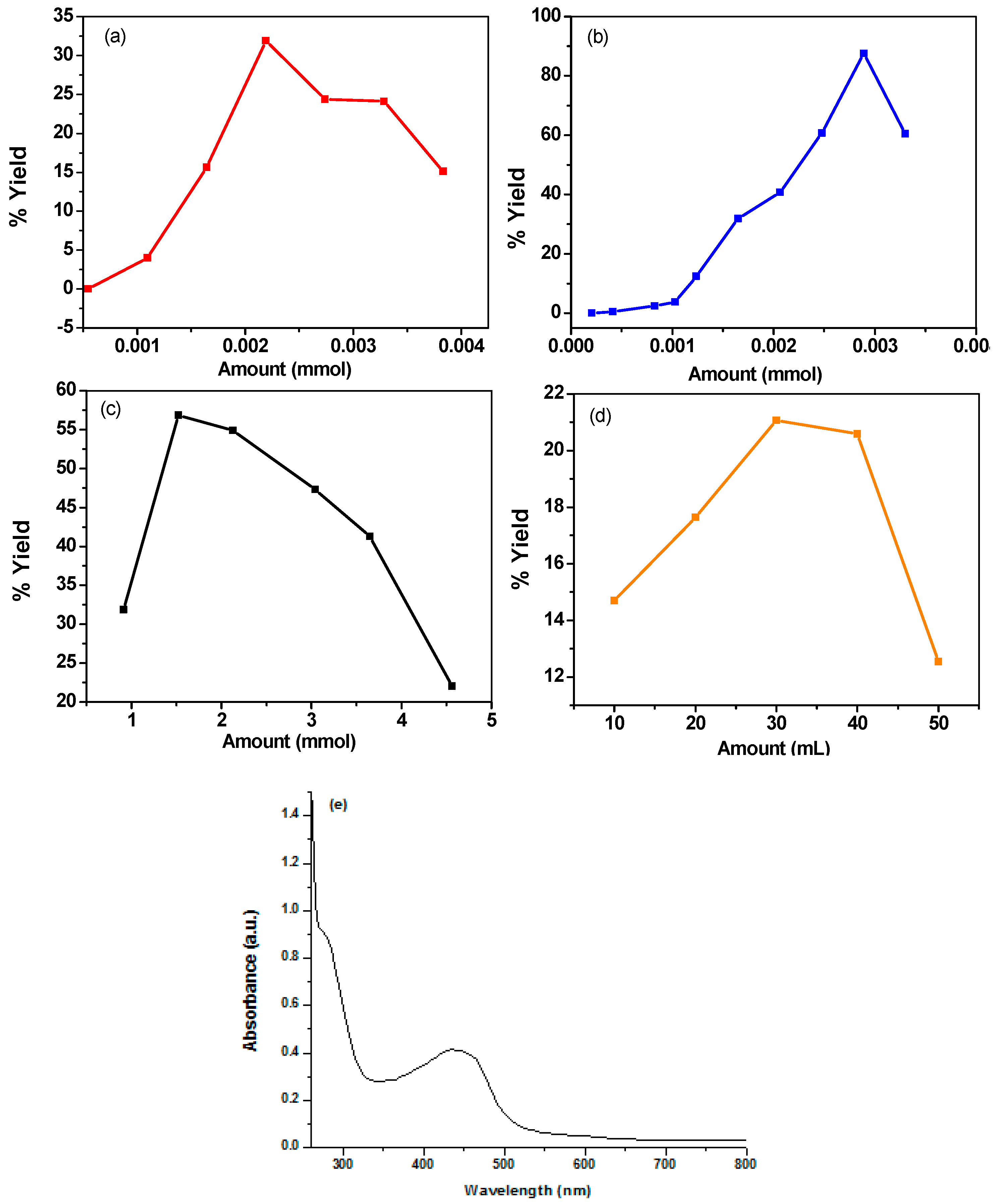
Materials 12 01527 g008
Figure 9. X-ray diffractogram of PANI salt.
Materials 12 01527 g009
Figure 10. CV of synthesized PANI samples coated on a gold sheet electrode, in 0.5 M H2SO4 at a scan rate of 50 mV/s (a) PANI A4 (b) PANI B9 (c) PANI D2 (d) PANI S3.
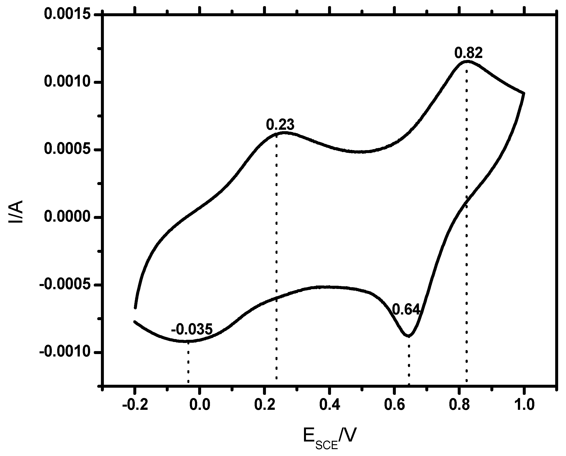
Materials 12 01527 g010
Figure 11. Cyclic voltammogram of PANI salt coated on a gold sheet electrode, in 0.5 M H2SO4 at a scan rate of 50 mV/s.
Materials 12 01527 g011
Figure 12. (a) Tafel plot of uncoated and different PANI coated stainless steel with different samples, as indicated. (b) Tafel plot of PANI coated via different no of drops on steel.
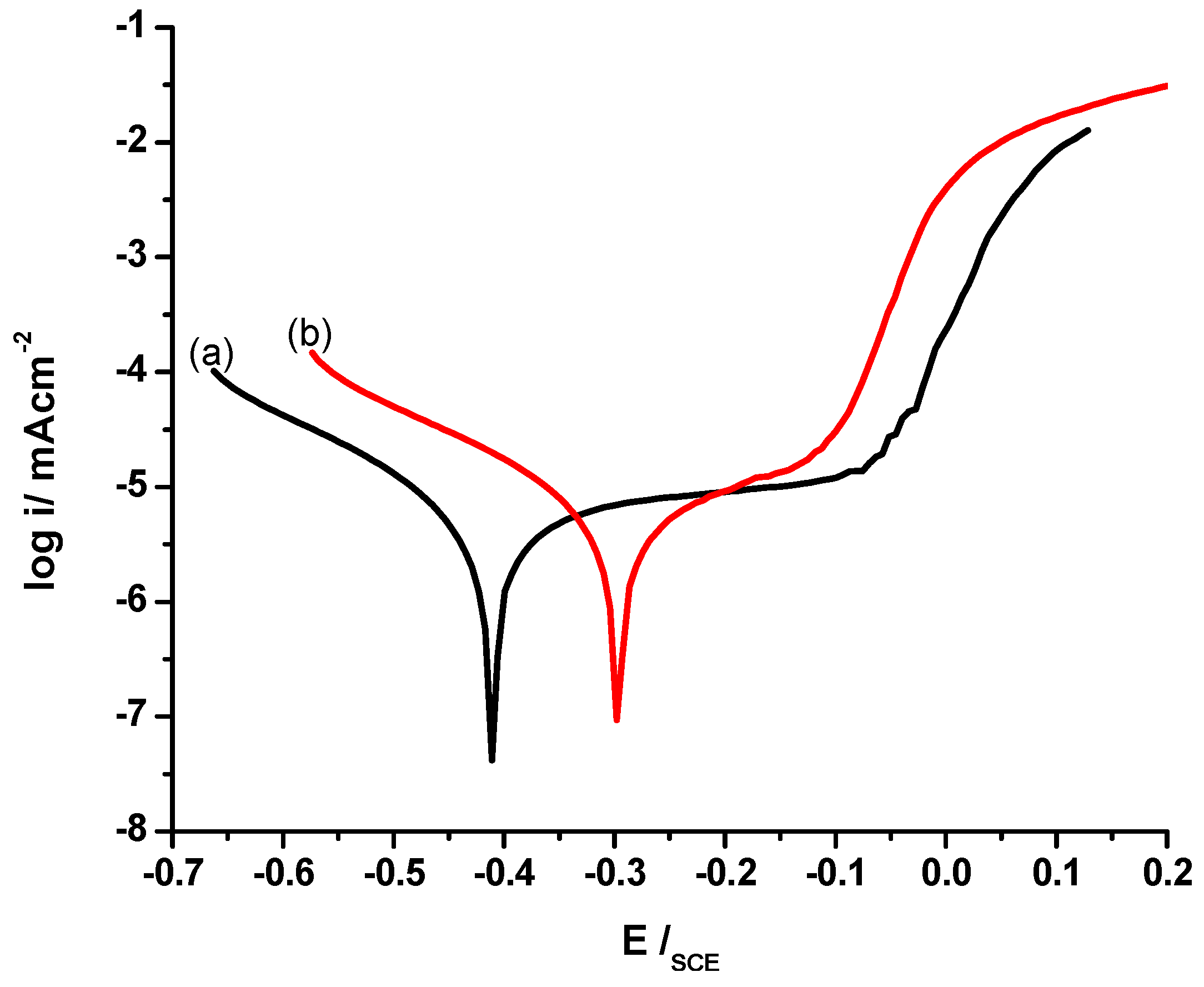
Materials 12 01527 g012
Figure 13. Tafel plot of (a) uncoated and, (b) PANI coated stainless steel.
Materials 12 01527 g013
Figure 14. Scanning electron micrograph (a) PANI A4 (b) PANI B9 (c) PANI D2 (d) and PANI S3.
Materials 12 01527 g014
Figure 15. Scanning electron micrograph of PANI salt.
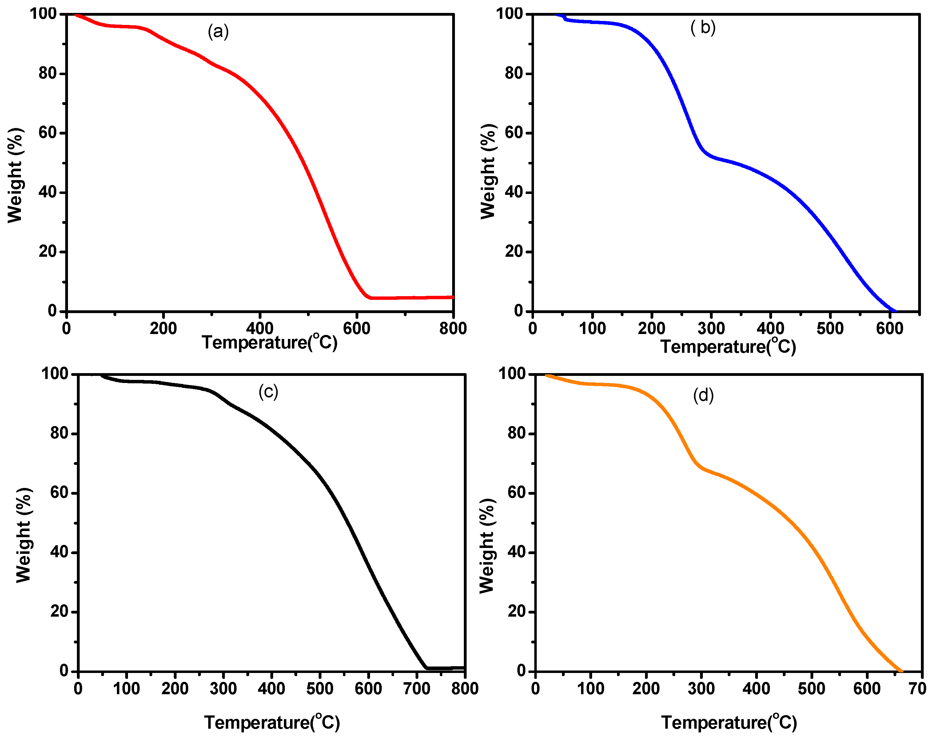
Materials 12 01527 g015
Figure 16. Thermograms of different (a) PANI A4 (b) PANI B9 (c) PANI D2 and (d) PANI S3.
Materials 12 01527 g016
Figure 17. TGA curve of PANI salt.
Materials 12 01527 g017
Table 1. Price of solvents in USD/L (2018/2019) and its effect on product properties.
Dispersion MediumPrice of Solvents in USD/LMaximum % YieldThermal Stability
(°C)
SolubilityReference
Chloroform1352.4480NMP, DMSO, dimethylformamide (DMF)[6]
Toluene22--Toluene, Xylene[11]
Toluene & iso octane22 & 158108–194320–499DMSO[16]
Toluene & 2-propanol22 & 2561-Chlorofrom, 2:1 mixture of toluene & 2-propanol, NMP, Dichloromethane.[7]
Chloroform & 2-butanol13 & 2225–305002:1 mixture of toluene + 2-propanol, chloroform, DMSO & DMF.[10]
n-hexane1281.97320-[17]
Diesel0.8387.6417Chloroform, NMP, DMSO, 1:3 Mixture of toluene & 2-propanolPresent work
Table 2. Effect of amount of monomer (aniline) on percent yield of PANI.
SerialNommol of AnilineWeight of the PANI (g)% yieldSample Code
10.550.0000.00PANI A1
21.100.0044.00PANI A2
31.600.02315.64PANI A3
42.200.06531.90PANI A4
52.740.06024.40PANI A5
63.300.07124.10PANI A6
73.830.05415.12PANI A7
Table 3. Effect of amount of oxidant (Benzoyl peroxide) on percent yield PANI.
Serial Nommol of OxidantWeight of PANI (g)% yieldSample Code
10.210.0000.00PANI B1
20.410.0010.49PANI B2
30.830.0052.45PANI B3
41.030.0083.92PANI B4
51.240.02612.74PANI B5
61.650.06531.86PANI B6
72.060.08040.8PANI B7
82.480.12460.7PANI B8
92.900.17887.6PANI B9
103.300.12360.4PANIB10
Table 4. Effect of amount of dopant (DBSA) on percent yield of PANI.
Serial Nommoles of DBSAWeight of PANI (g)% yieldSample Code
10.910.06531.86PANI D1
21.520.11656.86PANI D2
32.130.11254.90PANI D3
43.040.09647.05PANI D4
53.650.04522.05PANI D5
64.560.08441.17PANI D6
Table 5. Effect of amount of solvents (diesel/water) on percent yield of PANI.
Serial NoAmount of Organic Solvent (mL)Amount of Water (mL)Weight of PANI (g)% YieldSample Code
150100.02612.574PANI S1
240200.04220.58PANI S2
330300.04321.07PANI S3
420400.03014.70PANI S4
510500.03617.64PANI S5
Table 6. The extent of doping of DBSA into PANI Chain.
Serial NoSampleE/B
01PANI A42.21
02PANI D22.25
03PANI B92.14
04PANI S32.22
Table 7. Peak assignments in the FTIR spectra of PANI salt.
Serial NoPeak Positions (cm−1)Peak Assignment
01503 and 573 –SO3H and SO3−1 of DBSA
02798Out of plane C–H bending vibration
031002–SO3H of DBSA
041122In-plane bending vibration of C–H
051298C–N stretching of benzenoid ring
061467Benzenoid ring
071565Quinoid ring C–N strecting
082853 and 2916C–H stretching vibrations of aromatic aniline ring
093232Symmetric and asymmetric stretching of NH2 and NH
Table 8. Values of icorr (µA), Ecorr (mV), βA (V/decade), βC (V/decade) and CR (mm y−1) for different samples of PANI salt.
Materialicorr (µA)Ecorr (mV)βA (V/decade)βC (V/decade)CR (mm y−1)
Uncoated steel10.70−467.00.53040.27084.906
PANI A47.050−231.00.12430.18183.223
PANI B93.450−184.00.9590.25861.575
PANI D24.870−400.00.2720.2212.226
PANI S34.380320.00.28650.18752.000
PANI salt0.859−295.00.10860.11940.3927

