Brazier Effect of Thin Angle-Section Beams under Bending


1
Research Institute of Structural Engineering and Disaster Reduction, Tongji University, Shanghai 200092, China
2
State Key Laboratory of Disaster Reduction in Civil Engineering, Tongji University, Shanghai 200092, China
3
General Contracting Department, Shanghai Construction Group, Shanghai 200036, China
*
Author to whom correspondence should be addressed.
Sustainability 2018, 10(9), 3047; https://doi.org/10.3390/su10093047
Submission received: 30 July 2018
/
Revised: 18 August 2018
/
Accepted: 22 August 2018
/
Published: 27 August 2018
(This article belongs to the Special Issue Resilience and Sustainability of Civil Infrastructures under Extreme Loads)
Abstract
:Thin-walled section beams have Brazier effect to exhibit a nonlinear response to bending moments, which is a geometric nonlinearity problem and different from eigenvalue problem. This paper is aimed at investigating the Brazier effect in thin-walled angle-section beams subjected to pure bending about its weak axis. The derivation using energy method is presented to predict the maximum bending moment and section deformation. Both numerical analyses and experimental results were used to show the validity of the proposed formula. Numerical results show that the boundary condition can influence the results due to the end effect, and that the influence tends to be negligible when the length of angle beam goes up to 30 times as the length of beam side. When the collapse in experiments is governed by Brazier flattening, the moment vs. curvature curve deviates significantly from the linear beam theory, but coincides well with the proposed formula in consideration of the restraint due to limited span of experimental setup. It can be concluded that the proposed formula shows good agreement with numerical results and experimental results.
1. Introduction
When an initially straight thin-walled circular cylindrical shell is subjected to bending, there is a tendency for the cross section to become progressively more oval as the curvature increases. The moment–curvature response deviates significantly from the linear beam theory. This nonlinear bending response phenomenon is due to geometric nonlinearity and was first investigated by Brazier [1] in 1927, thus it is called Brazier effect or Brazier flattening. Brazier flattening is not an eigenvalue problem, which is different from buckling. The main characteristic of Brazier flattening is the reduction of flexural stiffness of the shell with the increase of curvature. Furthermore, under steadily increasing curvature, the bending moment has a maximum value that is defined as the instability critical moment, which is given by employing the well-known energy method. Reissner [2] reconsidered Brazier’s theory and demonstrated that Brazier’s solution is a first-order approximate solution. Reissner also derived the second-order approximate solution and found the maximum moment is 8% lower than the value Brazier had gotten. Either is a geometric nonlinearity problem based on elastic material.
Aksel’rad [3] developed the application of Brazier’s theory to finite length shells. Gerber [4] studied Brazier effect by taking the plastic properties into consideration. Tomasz and Sinmao [5] proposed a theoretical model to predict the bending moment and section deformation of cylindrical tubes under pure plastic bending. Li and Kettle [6] investigated the nonlinear bending response of finite length cylindrical shells with stiffening rings using a modified Brazier approach. Poonaya [7] developed a close-form solution of thin-walled circular tube subjected to bending using a rigid plastic mechanism analysis. Besides circular sections, studies also have been carried out on the analysis of other shapes. The deformation of angle-section beams has been analyzed by Yu [8], while it is not based on Brazier’s energy principle. The Brazier effect in elliptical cross sections, box sections, rectangular sections, airfoil sections, and wind turbine blades have been analyzed by Huber [9], Rand [10], Paulsen and Welo [11], Cecchini and Weaver [12] and Jensen [13], respectively. In addition, the Brazier effect of elastic pipe beams, single- and double-walled elastic tubes, and multilayered cylinders have been studied by Luongo [14], Sato [15], and Shima [16], respectively. The studes on the other shapes of sections demonstrated that all long thin-walled beams exhibit a nonlinear response to bending moments. However, the Brazier effect of angle-section beams is not yet studied on the basis of the variational method as Brazier have done for cylindrical tubes
A cylinder under bending, however, can also take place another instability phenomenon which is called bifurcation instability, i.e. buckling. The main characteristic of buckling is a form of longitudinal wavy type ‘wrinkles’ caused by the increased axial stress at the compression side due to ovalization. The interaction between Brazier flattening and bifurcation buckling has been investigated by many researchers such as Stephens [17], Fabian [18], Libai [19] and Karamanos [20]. Karamanos’s study shows that the interaction between the two instability modes depends on the value and the sign of the initial tube curvature. Tatting [21,22] investigated the local buckling behavior of composite shells associated with Brazier effect. Angle-section beams can firstly buckle and then suddenly collapse under additional bending moment and Brazier flattening. This phenomenon was found in the 1995 Hyogoken Nanbu earthquake [23], as illustrated in Figure 1.
In this paper, the Brazier effect in thin-walled angle-section beams subjected to pure bending about its weak axis is investigated. It is aimed to predict the maximum bending moment and section deformation under extreme loads, so as to study the sustainable load capacity of the angle steel. Theoretical analysis on the basis of the variational method was performed [1], and a formula to predict the maximum bending moment and section deformation was proposed. Both numerical results and experimental results were used to show the validity of the proposed theoretical formula. A number of beam section sizes were used for comparison. The least length of angle beam is also recommended to eliminate the end effect, i.e., the restraint due to limited beam length of the numerical model and experimental setup. The ratio of width to thickness to make sure that Brazier effect does not occur within elastic range is derived for angle beams. Furthermore, the bending moment of thin-walled angle beam considering elasto-plastic material is discussed as well.
2. Theoretical Derivation
2.1. Elastic Theoretical Analysis Based on Variational Method
Angle beam section is illustrated in Figure 2. The variational method can be applied to examine the equilibrium of the flange when the angle beam is bent by pure bending moment. Referring to Figure 3, a system of coordinates x, y, z, and of displacements u, v, w, is described. The axis of x is parallel to the beam axis and the axis of z is normal to the flange. The thickness of the flange is defined as t, the length of side as b, and the angle between flange and the symmetry axis of the section as α.
It is supposed that the beam is subjected to a constant axis curvature ϕ and that the stress at any point is proportional to the distance from the neutral axis. The flange is allowed to take up an inextensible system of deformation w, v. The condition of inextensibility is
Because of the geometrical symmetry of the section, the half section is analyzed. It can get that v = 0.
The change of curvature at a point can be obtained
The resultant distance from the neutral axis is
After neglecting squares and products of the small quantities w with respect to y, it thus can be obtained for the total strain energy between point A and point B per unit length of the beam the expression
In Equation (4), E is Young’s modulus and ν is Poisson ratio. If this is to be a minimum then according to the calculus of variations w must satisfy the following equation
where
The solution of Equation (5) is
Considerations of symmetry and of the free end effect require that Equations (8)–(11) are satisfied.
Solving the equations, we can get
If these expressions are substituted in Equation (4) and the integrations effected, we can obtain
The moment transmitted at a section of the beam is given by
This is a maximum when
at which point the moment is
Because of symmetry, the moment of the whole section is 2Mbr, that is
If Equation (15) is substituted in Equation (12), the extreme displacement wext at free end at this instant can be obtained,
so that the approximations based on the smallness of w are justified to this extent. The deformation of the cross section at this point is shown at Figure 4.
2.2. Threshold Ratio of Width to Thickness
The occurrence order of Brazier flattening and yielding is governed by the ratio of width to thickness of the angle-section beam. The upper limit ratio of width to thickness in order to make sure that Brazier flattening does not occur within elastic range is here called threshold ratio of width to thickness. In another words, the threshold ratio of width to thickness is the lower limit ratio to make sure that Brazier flattening occurs within elastic range. Yield moment My can be determined by Equation (19) using the initial shape of cross section.
According to , threshold ratio of width to thickness can be derived as
Considering a general steel, E = 205,000 , , , the threshold ratio of width to thickness is 354, 204 and 118 for α being 30°, 45°, and 60°, respectively. These ratio values are relatively large compared to the critical ratio for general local plate buckling. For general structural angle-section beams with the ratio of width to thickness being about 10, Brazier flattening will not occur within elastic limit. In other words, Brazier flattening within elastic limit is restricted to angle-section beams with large ratio of width to thickness. Accordingly, Brazier flattening is expected to couple with local buckling in a test as Brazier had met in his tests [1].
3. Finite Element Analysis
3.1. Elastic Finite Element Analysis
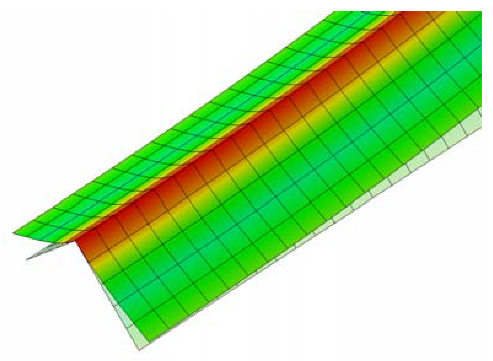
In order to test the validity of the proposed formula, static elastic analyses considering geometric nonlinearity have been performed using finite element code ABAQUS. The angle-section beam model is discretized by four node-reduced integration-hourglass control shell elements (S4R) as shown in Figure 5. In this model, b = 100 mm, t = 2.5 mm, α = 45°, E = 205,000 MPa, ν = 0.3. Considering the symmetry of the model, a half angle beam is meshed for analysis, with the symmetrical boundary condition enforced at the left end of the model. The bending moment is exerted through a rigid plate glued at the right end of the model. As the theoretical derivation is based on elastic material assumption, the material is firstly assumed to be elastic in order to observe the geometric nonlinear response caused by Brazier effect. Figure 6 shows a partial illustration of the superimposed undeformed and deformed shape of the model. Figure 7a,b illustrate the contours of Mises stress and rotational moment. Figure 8 shows the normalized numerical maximum moment (Mf/Mt) with the change of beam length. It can be seen from the figure that the maximum moments calculated from finite element analyses decrease with the beam length and tend to be converging when the beam length becomes longer. When the length l of angle beam goes up to 30 times as the length of edge length, the influence of the end effect tends to be negligible, and the pure bending condition is approached. Thus, this length is used for the analyses.
Comparison of numerical and theoretical elastic maximum moments is carried out using a number of beam section sizes, as illustrated in Table 1. Numerical values show agreement with these theoretical values, with the relative difference being −2.19–7.57%. It can be concluded that elastic theoretical analysis based on variational method is validated by finite element analyses.
3.2. Elasto-Plastic Finite Element Analysis
The above theoretical derivation is based on an elastic energy approach, which does not consider the plastic property of material. Herein, elasto-plastic finite element analysis is performed to show the influence of plasticity. The yielding strength is assumed as 325 MPa and the ultimate strength is assumed as 554 MPa. Then finite element analyses considering geometric nonlinearity and material nonlinearity were performed using ABAQUS. Comparison of the maximum moment for different analyses is shown in Table 2. It can be seen that the plastic property will significantly decrease the maximum moment of the angle-section beam when ratio of width to thickness is smaller than the critical value , which is 204 for the cases in Table 2. Plastic deformation will occur before Brazier flattening for these cases. The FEM value from the elasto-plastic analyses is approximate to the plastic moment, which can be calculated from Equation (21).
4. Comparison with Experimental Results
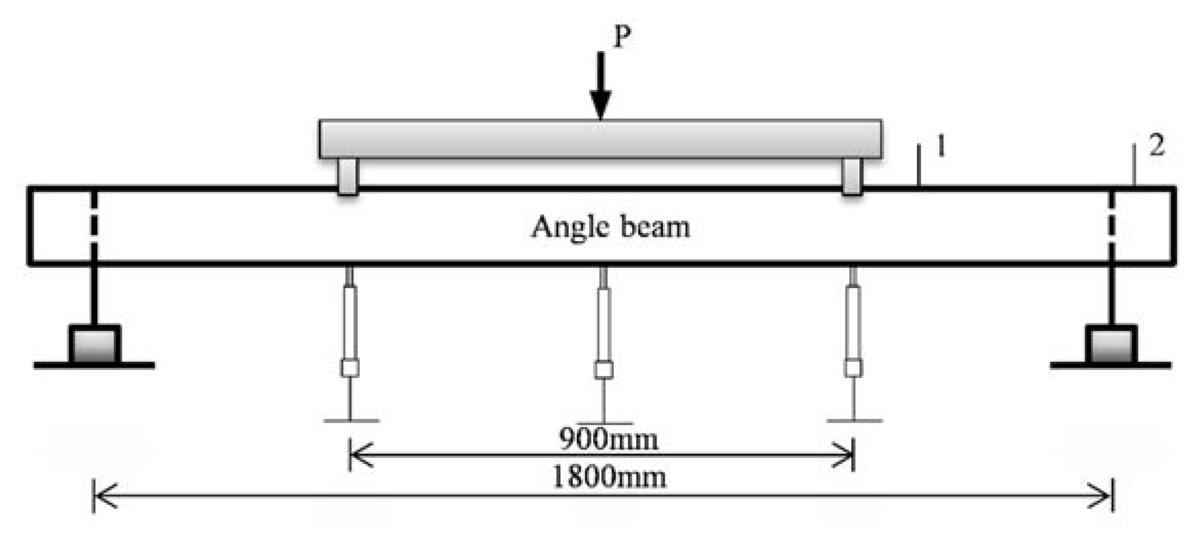
The result of a symmetrical four-point bending test was used to compare with theoretical results. The illustration of the experiment setup is shown in Figure 9. The total length of the thin-walled angle beam is 1800 mm. Three displacement meters were set to measure the vertical displacement at the load points and the center point. The material properties of the specimen are shown in Table 3.
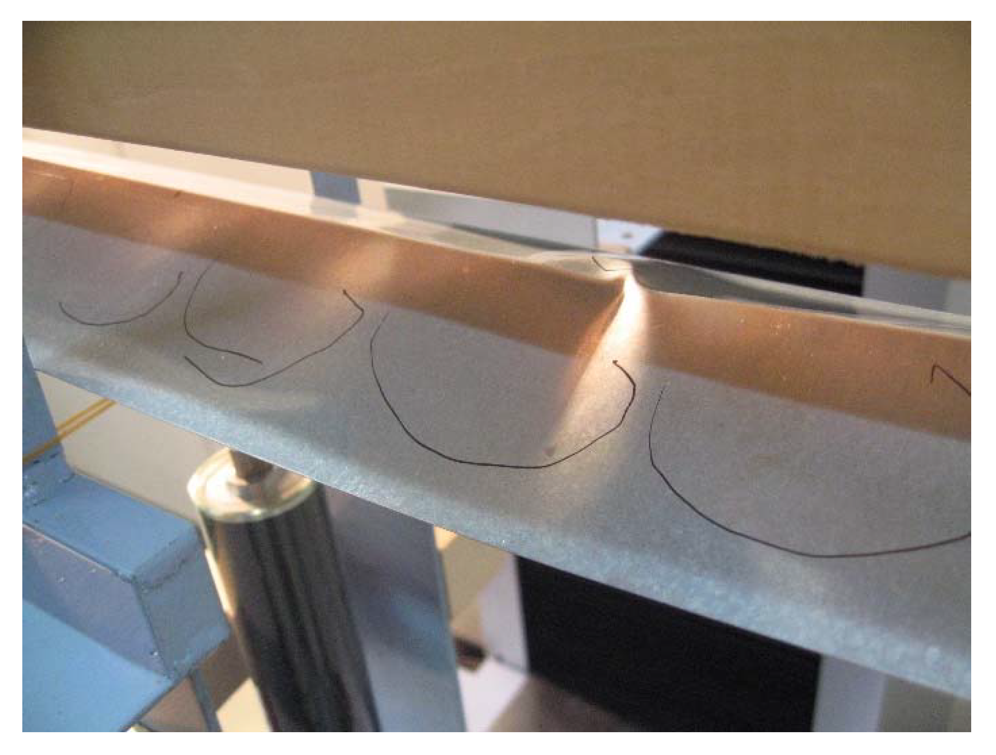
Two specimen types—i.e., specimen type A and B with individual kind of section sizes—were tested. The numerical, theoretical, and experimental results are shown in Table 4. As for the FEM analyses, both elastic and elasto-plastic material are considered. During the experiment, it was demonstrated that the wave of plate buckling was generated and developed, which obviously decreased the bending stiffness of the beam. Nevertheless, the collapse is not controlled by the plate buckling, but by Brazier flattening, load-point crippling, or ridge-line buckling. The collapse mode of specimen type A is Brazier flattening. When the collapse was governed by flattening, the moment–curvature curve is different from the linear beam theory, but well coincides with the flattening theory in consideration of the end effect. For specimen type A which shows Brazier flattening collapse, the theoretical maximum moment is 17.97% smaller than the experimental maximum moment and close to the numerical values. Substituting α = 60° and the parameter in Table 3 to Equation (20), the threshold ratio of width to thickness gets the value of 117, which is bigger than the ratio of width to thickness of specimen type A. This means that yielding happened in the specimen before Brazier flattening. The picture of Brazier flattening of specimen A3 is shown in Figure 10. However, for specimen type B, load-point crippling or ridge-line buckling occurred before Brazier flattening happens. Thus, the experimental max moments are far below theoretical value, Brazier flattening is unlikely to happen in specimen type B.
5. Conclusions
This paper mainly aims at presenting a theoretical analysis for Brazier effect in thin-walled angle-section beams. The variational method is applied to derive formulas to predict the maximum bending moment and section deformation of angle-section beams under pure bending about its weak axis. Both numerical analyses and experimental results were used to show the validity of the proposed formula. Numerical results show that the end effect can influence the numerical results, but the end effect can be eliminated by making the length of angle beam to thirty times as the length of beam side. During the experiment, it was demonstrated that the wave of plate buckling was generated and developed, which obviously decreased the bending stiffness of the beam. Nevertheless, the collapse is not controlled by the plate buckling, but by Brazier flattening, load-point crippling, or ridge-line buckling. When the collapse was governed by Brazier flattening, the moment–curvature curve is different from the linear beam theory, but coincides well with the flattening theory in consideration of the end effect. It can be concluded that the proposed formula shows good agreement with numerical results and experimental results.
Author Contributions
Z.Z. wrote the paper and directed the study. L.X. analyzed the data and revised the paper. C.S. performed the numerical analyses. S.X. conceived the idea, provided valuable discussions, and revised the paper. He took responsibility of the corresponding work.
Acknowledgments
The authors gratefully acknowledge the financial supports from the National Natural Science Foundation of China (No. 51478357) and a collaborative research project under International Joint Research Laboratory of Earthquake Engineering (ILEE) (No. ILEE-IJRP-P1-P3-2016).
Conflicts of Interest
The authors declare no conflict of interest.
References
- Brazier, L.G. On the flexure of thin cylindrical shells and other thin sections. Proc. R. Soc. Lond. Ser. A 1927, 116, 104–114. [Google Scholar] [CrossRef]
- Reissner, E. On finite bending of pressurized tubes. Trans. ASME 1959, 26, 386–392. [Google Scholar]
- Akselrad, E.L. Pinpointing the upper critical bending load of a pipe by calculating geometric nonlinearity. Izv. Akad. Nauk SSR. Mekh. 1965, 4, 133–139. [Google Scholar]
- Gerber, T.L. Plastic Deformation of Piping Due to Pipe-Whip Loading. 1974. Available online: http://jglobal.jst.go.jp/en/public/201002025727941512 (accessed on 22 August 2018).
- Tomasz, W.; Sinmao, M.V. A simplified model of Brazier effect in plastic bending of cylindrical tubes. Int. J. Press. Vessels Pip. 1997, 71, 19–28. [Google Scholar]
- Li, L.Y.; Kettle, R. Nonlinear bending response and buckling of ring-stiffened cylindrical shells under pure bending. Int. J. Solids. Struct. 2002, 39, 765–781. [Google Scholar] [CrossRef]
- Poonaya, S.; Teeboonma, U.; Thinvongpituk, C. Plastic collapse analysis of thin-walled circular tubes subjected to bending. Thin Wall. Struct. 2009, 47, 637–645. [Google Scholar] [CrossRef]
- Yu, T.X.; Teh, L.S. Large plastic deformation of beams of angle-section under symmetric bending. Int. J. Mech. Sci. 1997, 39, 829–839. [Google Scholar] [CrossRef]
- Huber, M.T. The Bending of Curved Tube of Elliptic Sections. In Proceedings of the Seventh International Congress for Applied Mechanics; Levy, H., Ed.; Her Majesty’s Stationery Office: London, UK, 1948; pp. 322–328. [Google Scholar]
- Rand, O. In-Plane Warping Effects in Thin-Walled Box Beams. AIAA J. 2000, 38, 542–544. [Google Scholar] [CrossRef]
- Paulsen, F.; Welo, T. Cross-Sectional Deformations of Rectangular Hollow Sections in Bending: Part II, Analytical Models. Int. J. Mech. Sci. 2001, 43, 131–152. [Google Scholar] [CrossRef]
- Cecchini, L.S.; Weaver, P.M. Brazier effect in multibay airfoil sections. AIAA J. 2005, 43, 2252–2258. [Google Scholar] [CrossRef]
- Jensen, F.M.; Weaver, P.M.; Cecchini, L.S. The Brazier effect in wind turbine blades and its influence on design. Wind Energy 2012, 15, 319–333. [Google Scholar] [CrossRef]
- Luongo, A.; Zulli, D.; Scognamiglio, I. The Brazier effect for elastic pipe beams with foam cores. Thin-Wall Struct. 2018, 124, 72–80. [Google Scholar] [CrossRef]
- Sato, M.; Ishiwata, Y. Brazier effect of single- and double-walled elastic tubes under pure bending. Struct. Eng. Mech. 2015, 53, 17–26. [Google Scholar] [CrossRef]
- Shima, H.; Sato, M.; Park, S.J. Suppression of Brazier Effect in Multilayered Cylinders. Adv. Condens. Matter Phys. 2014, 10, 11–55. [Google Scholar] [CrossRef]
- Stephens, W.B.; Starnes, J.J. Collapse of long cylindrical shells under combined bending and pressure loads. AIAA J. 1975, 13, 5–20. [Google Scholar]
- Fabian, O. Collapse of cylindrical, elastic tubes under combined bending, pressure and axial loads. Int. J. Solids Struct. 1977, 13, 1257–1270. [Google Scholar] [CrossRef]
- Libai, A.; Bert, C.W. A mixed variational principle and its application to the nonlinear bending problem of orthotropic tubes-II. Application to nonlinear bending of circular cylindrical tubes. Int. J. Solids Struct. 1994, 31, 1019–1033. [Google Scholar] [CrossRef]
- Karamanos; Spyros, A. Bending instabilities of elastic tubes. Int. J. Solids Struct. 2002, 39, 2059–2085. [Google Scholar] [CrossRef]
- Tatting, B.F.; Gürdal, Z. Nonlinear shell theory solution for the bending response of orthotropic finite length cylinders including the Brazier effect. In Proceedings of the 36th Structures, Structural Dynamics and Materials Conference, New Orleans, LA, USA, 10–13 April 1995. [Google Scholar]
- Tatting, B.F.; Gürdal, Z.; Vasiliev, V.V. The Brazier effect for finite length composite cylinders under bending. Int. J. Solids Struct. 1997, 34, 1419–1440. [Google Scholar] [CrossRef]
- Makoto, W.; Gakkai, N.H. Preliminary Reconnaissance Report of the 1995 Hyogoken-Nanbu Earthquake; The Architectural Institute of Japan: Tokyo, Japan, 1995. [Google Scholar]
- Kuwamura, H. Flattening and buckling of thin angle-section beams. In Proceedings of the Fifth International Conference on “Coupled Instabilities in Metal Structures” CIMS2008, Sydney, Australia, 23–25 June 2008; pp. 101–108. [Google Scholar]
Figure 1.
Diagonal brace collapsed in the 1995 Hyogoken Nanbu earthquake [23].
Figure 1.
Diagonal brace collapsed in the 1995 Hyogoken Nanbu earthquake [23].

Figure 2.
Angle beam section.
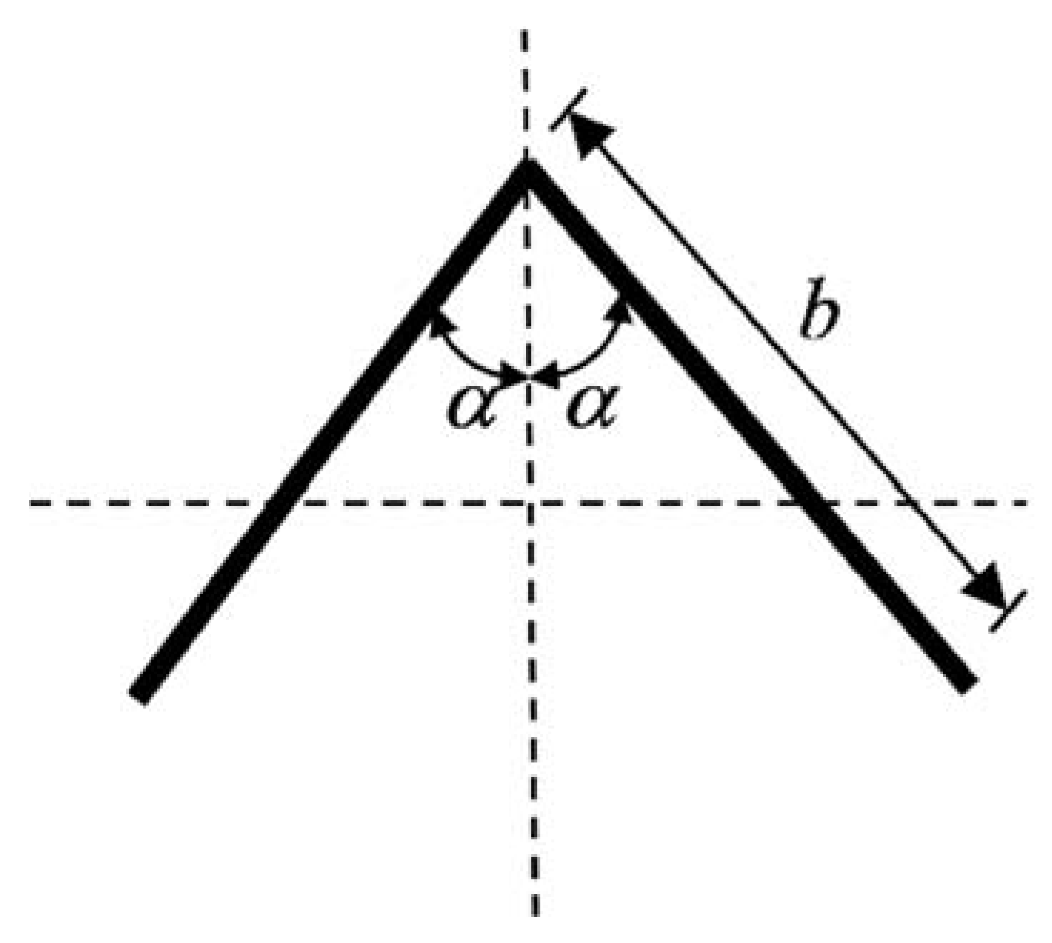
Figure 3.
System of coordinate.
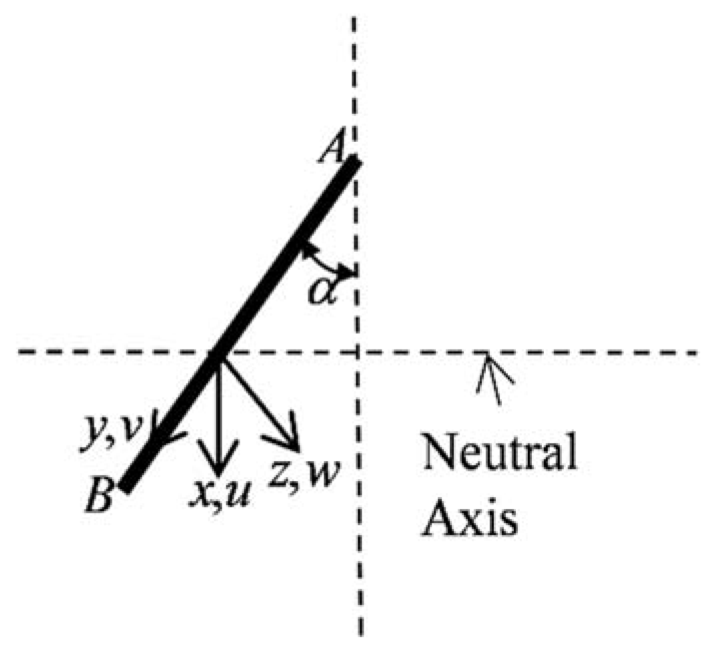
Figure 4.
Deformation of angle beam.

Figure 5.
Finite element model.
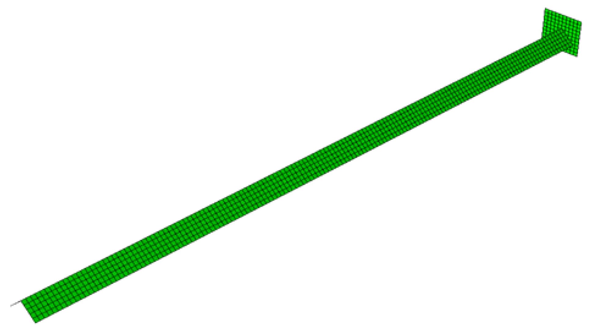
Figure 6.
Defomed and undeformed shape.

Figure 7.
FEM Results: (a) Mises stress; (b) rotational moment.
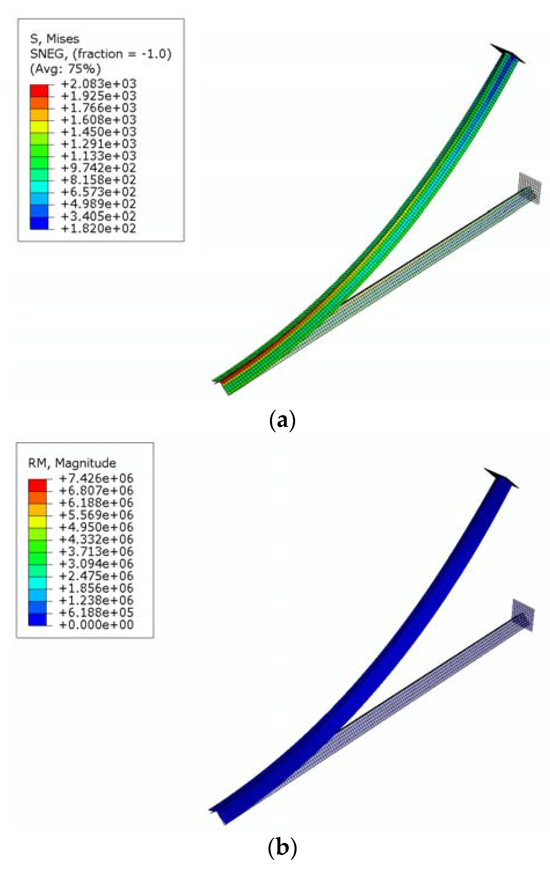
Figure 8.
Normalized numerical maximum moment versus the ratio of beam length to edge length.
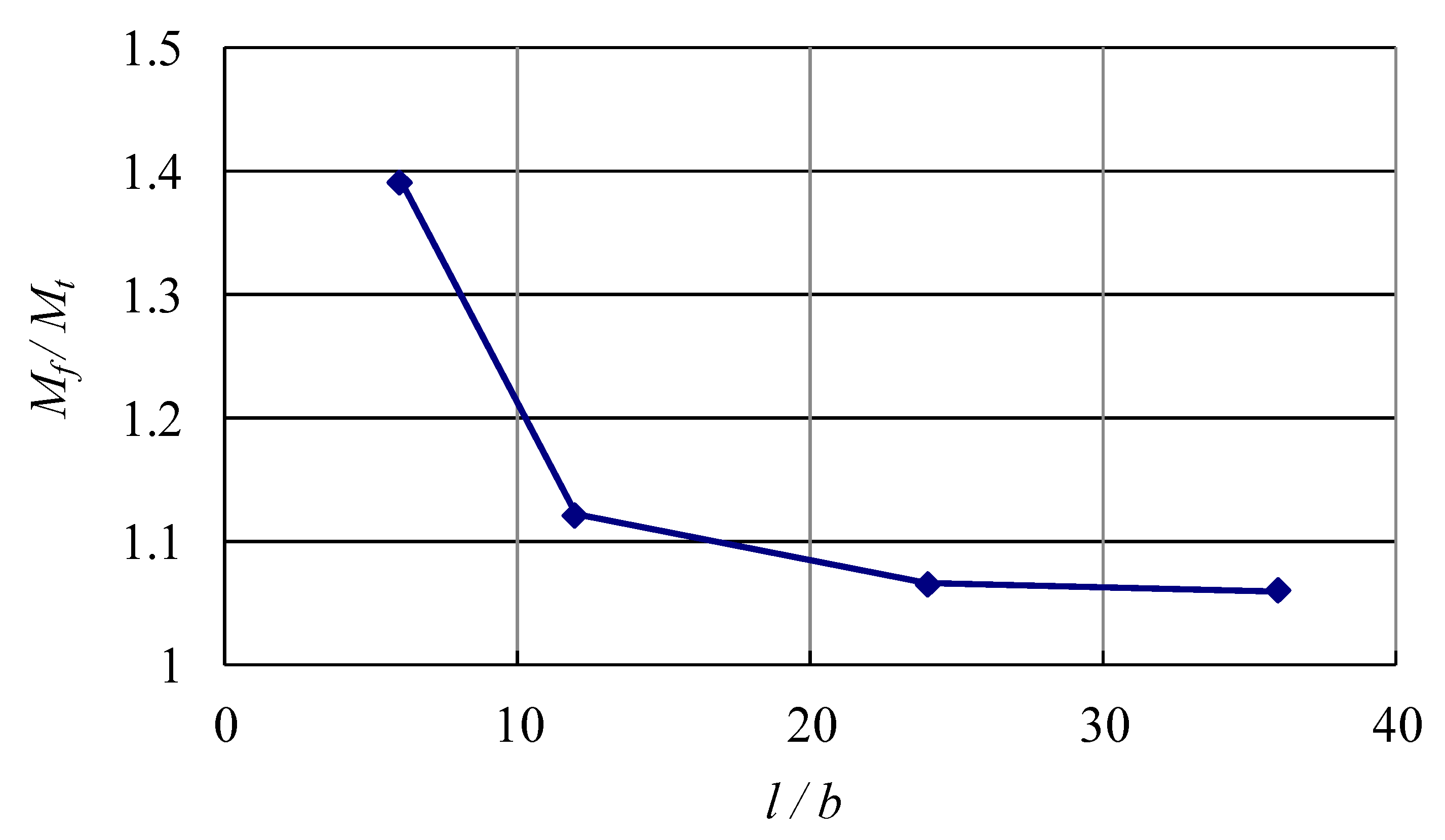
Figure 9.
Experiment setup of the four-point bending test [24].
Figure 9.
Experiment setup of the four-point bending test [24].

Figure 10.
Brazier flattening of specimen A3.


Table 1.
Comparison of numerical and theoretical elastic maximum moments
| Size | Numerical Value (N × mm) | Theoretical Value (N × mm) | Relative Difference (%) | ||
|---|---|---|---|---|---|
| b (mm) | b/t | α | |||
| 50 | 50 | 45° | 5.97 × 10⁵ | 5.66 × 10⁵ | +5.59 |
| 100 | 4.82 × 10⁶ | 4.52 × 10⁶ | +6.45 | ||
| 200 | 3.80 × 10⁷ | 3.62 × 10⁷ | +4.86 | ||
| 100 | 40 | 45° | 7.55 × 10⁶ | 7.07 × 10⁶ | +6.75 |
| 50 | 4.82 × 10⁶ | 4.52 × 10⁶ | +6.45 | ||
| 60 | 3.33 × 10⁶ | 3.14 × 10⁶ | +5.82 | ||
| 100 | 50 | 30° | 9.39 × 10⁶ | 9.60 × 10⁶ | −2.19 |
| 45° | 4.82 × 10⁶ | 4.52 × 10⁶ | +6.45 | ||
| 60° | 1.99 × 10⁶ | 1.85 × 10⁶ | +7.57 | ||
Table 2.
Comparison of maximum moments for elastic and elasto-plastic analyses
| Size | FEM Value (N × mm) | Elastic Theoretical Value (N × mm) | Relative Difference (%) | ||||
|---|---|---|---|---|---|---|---|
| b (mm) | b/t | α | Elastic | Elasto-Plastic | FEM Elastic | FEM Elasto-Plastic | |
| 100 | 40 | 45° | 7.55 × 10⁶ | 2.63 × 10⁶ | 7.07 × 10⁶ | 6.75 | −62.80 |
| 50 | 4.82 × 10⁶ | 2.04 × 10⁶ | 4.52 × 10⁶ | 6.45 | −54.88 | ||
| 60 | 3.33 × 10⁶ | 1.65 × 10⁶ | 3.14 × 10⁶ | 5.82 | −47.45 | ||
Table 3.
Material properties of the specimen [24].
Table 3.
Material properties of the specimen [24].
| Material | Flange Thickness t (mm) | Young’s Modulus E (GPa) | Poisson’s Ratio ν | Yielding Strength σy (MPa) |
|---|---|---|---|---|
| Steel | 0.324 | 199,000 | 0.3 | 300 |
Table 4.
Comparison of numerical, theoretical, and experimental results
| Specimen No. | A1 | A2 | A3 | B1 | B2 | |
|---|---|---|---|---|---|---|
| Size | L (mm) | 1800 | 1800 | |||
| α | 60° | 45° | ||||
| b (mm) | 30 | 60 | ||||
| Experimental max moment (N × mm) | 1.61 × 10⁴ | 1.60 × 10⁴ | 1.58 × 10⁴ | 4.83 × 10⁴ | 5.07 × 10⁴ | |
| Collapse mode | Brazier Flattening | Load-point crippling | Ridge-line buckling | |||
| Elastic theoretical max moment (N × mm) | 1.31 × 10⁴ | 6.41 × 10⁴ | ||||
| FEM max moment (N × mm) | Elastic | 1.51 × 10⁴ | 7.84 × 10⁴ | |||
| Elasto-plastic | 1.31 × 10⁴ | 7.13 × 10⁴ | ||||
| Relative difference to experimental value (%) | Theoretical value | −17.97 | 29.49 | |||
| Elastic | −5.44 | 58.38 | ||||
| Elasto-plastic | −17.97 | 44.04 | ||||
© 2018 by the authors. Licensee MDPI, Basel, Switzerland. This article is an open access article distributed under the terms and conditions of the Creative Commons Attribution (CC BY) license (http://creativecommons.org/licenses/by/4.0/).
Share and Cite
MDPI and ACS Style
Zhou, Z.; Xu, L.; Sun, C.; Xue, S. Brazier Effect of Thin Angle-Section Beams under Bending. Sustainability 2018, 10, 3047. https://doi.org/10.3390/su10093047
AMA Style
Zhou Z, Xu L, Sun C, Xue S. Brazier Effect of Thin Angle-Section Beams under Bending. Sustainability. 2018; 10(9):3047. https://doi.org/10.3390/su10093047
Chicago/Turabian StyleZhou, Zhiguang, Liuyun Xu, Chaoxin Sun, and Songtao Xue. 2018. "Brazier Effect of Thin Angle-Section Beams under Bending" Sustainability 10, no. 9: 3047. https://doi.org/10.3390/su10093047
Note that from the first issue of 2016, this journal uses article numbers instead of page numbers. See further details here.