Article

Electromagnetic Design Optimization Integrated with Mechanical Stress Analysis of PM-Assisted Synchronous Reluctance Machine Topologies Enabled with a Blend of Magnets †

Department of Electrical and Computer Engineering, Marquette University, Milwaukee, WI 53233, USA
*
Author to whom correspondence should be addressed.
This paper is an extended version of our paper published in “2023 IEEE Energy Conversion Congress and Exposition (ECCE), Nashville, TN, USA, 29 October–2 November 2023; pp. 3930–3937”.
Energies 2024, 17(8), 1873; https://doi.org/10.3390/en17081873
Submission received: 14 March 2024 / Revised: 11 April 2024 / Accepted: 12 April 2024 / Published: 14 April 2024

Abstract

:
Permanent Magnet-Assisted Synchronous Reluctance Machines (PMASynRM) provide a low-cost alternative to Surface PM Machines due to the use of relatively lower grades of rare-earth (RE) or RE-free magnets, as the performance degradation due to weaker magnets is compensated by the presence of reluctance torque. However, the weaker magnets suffer from a high risk of demagnetization, leading to unreliable motor operation. Using a blend of RE and RE-free magnets has the potential to overcome this issue. This paper proposes to blend different grades of various rare-earth (RE) and rare-earth-free (RE-free) magnets in six different combinations and utilizes them in two-layer and three-layer U-shaped PMASynRM topologies with both eight-pole and six-pole variations. The rotor of the various designs is then optimized using a differential evolution (DE) based optimization algorithm to obtain low-cost designs with reduced RE magnet volume and minimum demagnetization risk. The optimization of each design is also integrated with the evaluation of mechanical stresses in the rotor laminations so as to maintain the stresses below the material yield strength. Furthermore, the various performance metrics, such as toque–speed/power–speed characteristics, demagnetization, and efficiency maps, are evaluated for each of the optimized and mechanically feasible designs. A quantitative comparison of the various optimized designs is also obtained to highlight the various trade-offs. The results indicate the feasibility of meeting the baseline torque requirement across the entire speed range, even with a 100% reduction in RE magnet volume and less than 5% demagnetization risk, while achieving a cost reduction exceeding 50%. Moreover, the two-layer, eight-pole designs exhibit relatively higher performance, whereas the three-layer, eight-pole designs are found to be the most economical option.

1. Introduction

Current trends in the automotive industry point toward a rapid expansion in the electric mobility (e-mobility) market. This has spurred extensive research aimed at reducing the cost of various components in electric vehicles. Owing to the integrated advantages of both magnet torque and reluctance torque, Permanent Magnet-Assisted Synchronous Reluctance Machines are capable of providing high torque/power density and wide speed range [1,2,3,4,5]. Enabling PMASynRMs with low-cost rare earth (RE)-free magnets can be one approach to achieve a cost-effective solution [5,6,7,8,9,10,11,12,13,14]. However, due to the relatively lower remanence and coercivity of RE-free magnets, the motor performance is adversely affected in terms of reduced output torque and heightened risk of permanent demagnetization of magnets under overload conditions and extreme operating temperatures [15,16].
An alternative cost-effective approach with improved performance was suggested in [8], involving the use of a U-shaped interior Permanent Magnet (PM) machine by combining rare-earth and ferrite magnets. However, the demagnetization performance was not assessed. In [9], a three-layer arc-shaped Hybrid PMASynRM was proposed, incorporating NdFeB and ferrite magnets in a series arrangement, aiming to enhance torque density and reduce irreversible demagnetization during flux-weakening operation. The design was constrained to a single rotor shape with a fixed magnet arrangement in all layers. In [4], the authors presented U-shaped PMASynRMs with two-layer, three-layer, and four-layer configurations incorporating ferrite magnets. Additionally, a two-layer PMASynRM with a mixed magnet configuration was proposed. Although mixed magnets yielded higher power and efficiency at a lower cost, the discussion focused on only two types of magnet arrangements. In [10], a three-layer U-shaped PMASynRM with NdFeB and ferrite magnets in various arrangements was compared to the Prius 2010 motor. Some combinations achieved higher torque/USD but had lower power factor, torque density, and higher torque ripple. However, the optimization of magnet and flux barrier dimensions was not addressed. In [11], the authors introduced a three-layer, eight-pole Hybrid PMASynRM, wherein the incorporation of a small quantity of RE magnets alongside ferrite, forming a series flux path, enhanced the demagnetization performance of ferrite PMs, along with improving the motor power factor and efficiency. In [7], the authors presented the optimization of a single-layer U-shaped, eight-pole Interior PM machine. By incorporating RE magnets along with ferrites in a parallel flux path arrangement, an enhancement in demagnetization withstand capability was achieved, simultaneously meeting the desired torque performance with 30% fewer RE magnets. However, a systematic demagnetization analysis was not provided. In [12], a three-layer, eight-pole PMASynRM was optimized, utilizing a combination of RE and ferrite magnets in both series and parallel flux path arrangements. The parallel design fulfilled torque requirements with 25% fewer RE magnets, eliminating demagnetization risk at both extremely low and high operating temperatures. However, the analysis was primarily focused on a demagnetization study, and a comprehensive performance evaluation was not presented. In [13], a multi-objective design optimization of a PMASynRM with a combination of NdFeB and ferrite magnets in a parallel configuration was suggested. An optimized design with a 40% reduction in rare-earth material compared to the baseline and minimized demagnetization risk at −20 °C was achieved.
However, it is crucial to acknowledge that the analyses conducted in the previously discussed articles are constrained to a specific magnet combination, namely, NdFeB and ferrite, and are performed at a single operating speed. In [14], five different combinations of RE and RE-free magnets were proposed and employed for the design optimization of a three-layer, U-shaped PMASynRM. The objective was to minimize the use of rare-earth material, maximize torque at four operating speeds, and minimize the demagnetization risk. Nevertheless, the analysis was confined to the three-layer rotor topology, and the demagnetization risk and torque ripple obtained for the optimized designs of certain magnet combinations were notably high. Furthermore, the method used for calculating demagnetization risk in the optimization could be enhanced.
The articles mentioned above clearly suggest that by utilizing a combination of RE and RE-free magnets and properly optimizing the designs, it is possible to achieve the desired performance with a reduced volume of RE magnets. Several methods have been presented in the literature to perform machine design optimization. The optimization process mainly involves the design modeling of a machine, followed by the optimization of the design parameters using various optimization algorithms. The authors in [17,18,19] presented analytical modelling of machines to perform the design optimization. Such a type of modeling is highly complex, especially for Interior PM machines, and lacks accuracy. In [11,20,21,22,23], the design optimization of a machine was conducted using a response surface model (RSM). Since this technique relies on constructing an empirical model derived from the correlation between input variables and responses, the accuracy of the optimization is contingent upon the accuracy of the surrogate model. The Finite Element (FE) model-based optimization method outlined in [24,25,26,27,28,29,30], despite its computational intensity, stands out as the most precise approach for machine design optimization. Several attempts have been made to make it computationally more efficient. In [28,29,30,31], the authors presented a computationally efficient FEA (CE-FEA) technique coupled with a multi-objective DE-based optimization algorithm to optimize the machine’s performance. However, this technique utilizes magnetostatic FE solutions at different rotor positions to construct time-stepped waveforms for various performance parameters used in optimization, which makes it a fairly complex method. The time-stepped FEA method, although time-consuming, offers a simplified approach with high accuracy. The emergence of high-performance computing (HPC) environments, compatible with multiple software licenses, enables the exploitation of parallel processing for FEA simulations, thereby enhancing the computational efficiency of the time-stepped FEA approach [32,33]. The authors in [14] used a time-stepped FEA method coupled with a based optimization algorithm to optimize the PMASynRM rotor enabled with five different magnet combinations. However, the optimization algorithm faced challenges in converging onto the best solutions due to a lack of accuracy in the selection criteria, thus impeding Pareto front generation for various conflicting objectives. Moreover, the analysis conducted so far lacks considerations for the mechanical stress analysis in the optimization process, potentially resulting in the generation of practically infeasible designs.
This paper addresses the limitations identified in [14] by employing the time-stepped FEA method coupled with a based multi-objective design optimization algorithm featuring enhanced selection criteria to improve the convergence of solutions. The optimization process is further coupled with FEA-based mechanical stress analysis to ensure the selection of optimal design candidates viable for practical implementation. Additionally, a more precise method for evaluating the magnet demagnetization risk is also integrated into the optimization process. Several PMASynRM topologies incorporating combinations of two RE magnets with a novel RE-free magnet material called Iron Nitride and a high-performance ferrite are optimized to obtain a cost-effective solution for EVs. Initially, a three-layer, eight-pole topology, as presented in [14], is adopted and modified to reduce the demagnetization risk of magnets. The design optimization of the modified three-layer and two-layer topologies for the eight-pole configuration, as outlined in [34], is further extended to incorporate a detailed comparison with a two-layer, six-pole variation. The volume of various magnets within each rotor topology is optimized to achieve two primary goals: minimizing the rare-earth content and mitigating the risk of demagnetization while ensuring that the desired torque is maintained across the entire range of operating speeds. The optimal design candidates obtained for various topologies of each magnet combination are further utilized for a detailed performance evaluation, including torque–speed/power–speed characteristics, torque ripple, efficiency maps, back-EMF reduction due to demagnetization, as well as identifying the local areas of demagnetization in individual magnets for each specific design. Moreover, a cost assessment of the optimal designs is conducted based on the total magnet mass in each design. A quantitative comparison of the various optimized designs based on the evaluated performance parameters is also presented to highlight the various trade-offs.

2. Machine Topology and Specifications

The description of the various machine topologies used in this analysis is discussed as follows.

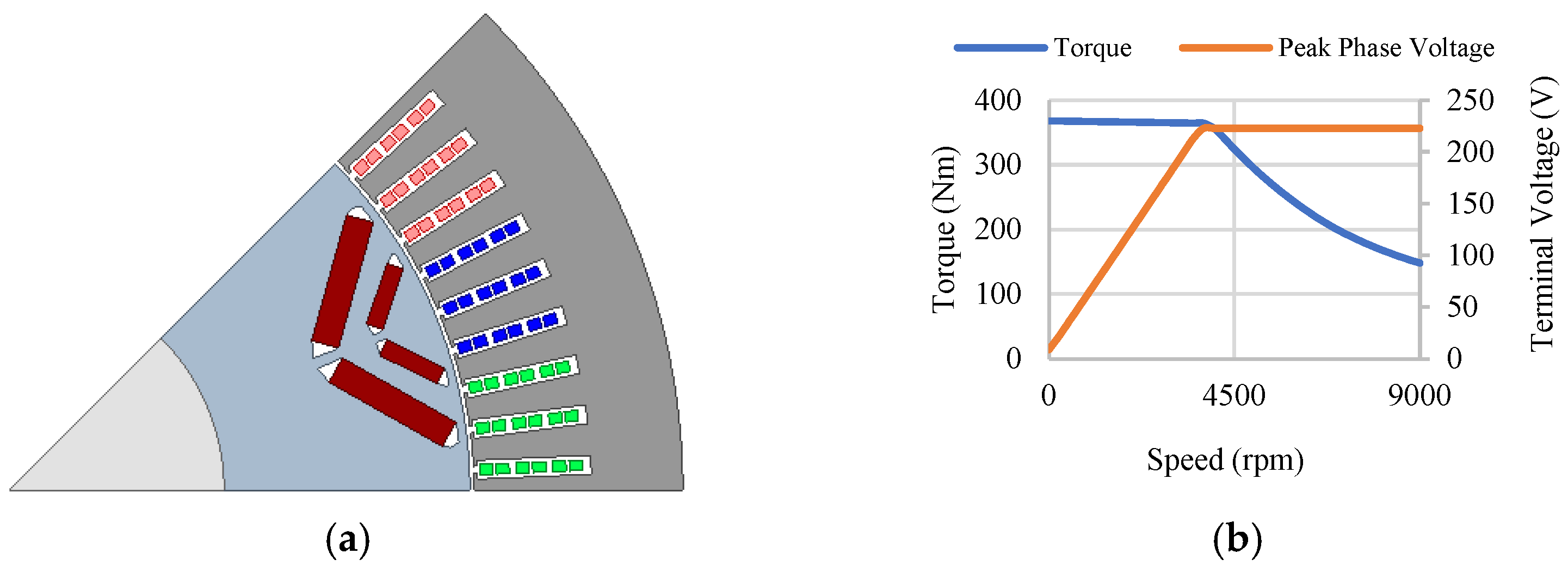
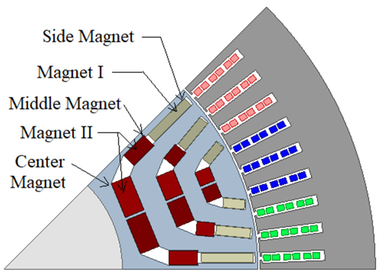
2.1. Baseline Design

As discussed earlier, the objective of this work is to obtain a low-cost design for EV applications. For this, the target torque and other performance requirements need to be fixed based on an existing EV motor in the market. As a result, the Chevy Bolt IPM motor, having a two-layer, eight-pole V-shaped rotor with NdFeB magnets, is selected as the baseline design, as shown in Figure 1a [14]. The motor design and performance specifications are tabulated in Table 1, and its torque–speed and terminal voltage characteristics are shown in Figure 1b.

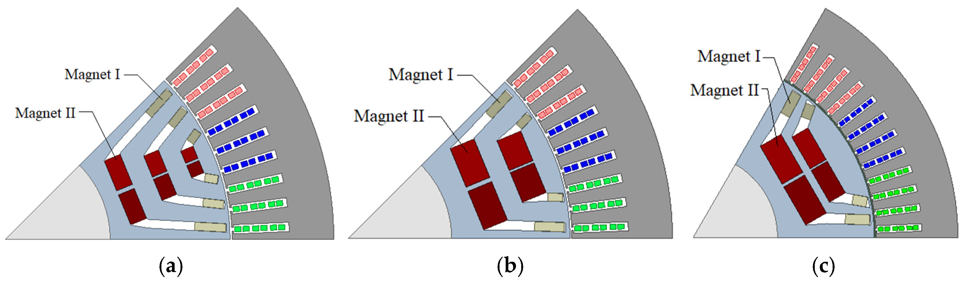
2.2. Initial PMASynRM Topology

Since the baseline EV motor is required to be replaced with a low-cost PMASynRM design, the stator, rotor, and shaft dimensions must be kept the same. Additionally, to obtain similar electromagnetic performance as the baseline motor as well as a fair comparison, the stator winding configuration as well as the conductor excitation are also kept unchanged. However, the V-shaped rotor structure of the baseline design is replaced with a three-layer, eight-pole U-shaped rotor, as shown in Figure 2, to obtain an initial PMASynRM design. The three-layer rotor with parallel magnet configuration is selected based on the study shown in [12], which indicates superior performance for parallel arrangement compared to the series configuration. The NdFeB magnets in the baseline design are replaced with a combination of two different types of magnets labeled Magnet I and Magnet II in Figure 2. Each magnet combination is composed of a blend of either a RE magnet and a RE-free magnet or two RE-free magnets. The coercivity and knee point of the magnet materials play a significant role in the placement of each type of magnet. The magnet materials having knee points in the third quadrant can be positioned near the air gap, like Magnet I. Meanwhile, the materials with knee points in the second quadrant can be placed at Magnet II locations to reduce their risk of demagnetization. Based on these criteria, the various magnet combinations and their positioning can be obtained as outlined in Table 2. The B-H curves for the various magnet materials at a normal operating temperature of 70 °C are shown in Figure 3, which will be utilized for performance evaluations of various designs. Since the magnet materials have a higher risk of demagnetization at extremely low and extremely high temperatures, the B-H curves at −20 °C and 150 °C, as shown in Figure 4a and Figure 4b, respectively, will be utilized for the demagnetization analysis of various designs.

2.3. Modified PMASynRM Topology

The initial PMASynRM topology discussed in the pervious section was optimized using various magnet combinations in [14], and a detailed study on demagnetization performance of various designs was presented in [14,35]. It was observed that the magnets having low coercivity and the knee point lying high in the second quadrant experience significantly high level of demagnetization at the locations shown as the middle and side magnets in Figure 2. A simple way to reduce demagnetization is to remove the demagnetized region, as suggested in [13]. Thus, a modified topology with reduced demagnetization can be obtained by removing the middle magnets for both three-layer and two-layer configuration, as depicted in Figure 5a and Figure 5b, respectively [36]. Consequently, Magnet I for the C6 magnet combination in Table 2 is assigned as air, as opposed to FeN used in [35]. The topology can also be extended to the six-pole variation, as shown in Figure 5c. For the six-pole configuration, the rotor topology remains the same as the eight-pole rotor, except for the variation in number of poles. The number of stator slots and series turns per phase are kept constant to maintain the same electrical loading so that a fair comparison between different topologies can be ensured. The number of conductors per slot, parallel paths, and conductor current density are also the same for all the designs. However, the number of slots per pole per phase (SPP) for the six-pole design increases to four compared to three for the eight-pole designs.

3. Design Optimization

The various PMASynRM topologies discussed in the last section represent reduced rare-earth magnet configurations as they employ a combination of RE and RE-free magnets presented in Table 2. However, to achieve motor performance similar to the Chevy Bolt motor, the discussed machine topologies are required to be optimized for each magnet combination.

3.1. Design Constraints and Objectives

As discussed earlier, the utilization of low-cost RE-free magnets in combination with RE magnets in PMASynRM topologies contributes to cost reduction. To achieve a further reduction in cost, the volume of RE magnets in each design needs to be minimized while attaining performance comparable to the Chevy Bolt motor. Consequently, the torque and terminal voltage characteristics of the Chevy Bolt motor at different operating speeds, given in Table 1 and shown in Figure 1b, can be taken as the reference torque values to be achieved. Based on this, the various design constraints for the design optimization can be defined using Equations (1) and (2).
C 1 k ( X ) = T k g ( X ) T k r 0 k = 1 , 2 , 3 , 4 ;   g = 1 , , g max
C 2 k ( X ) = V r V k g ( X ) 0 k = 1 , 2 , 3 , 4 ;   g = 1 , , g max
where C 1 k and C 2 k are the two constraint functions. The values of k correspond to the four operating speeds—3750 rpm, 5000 rpm, 7000 rpm, and 9000 rpm. Thus, T k r corresponds to the reference torque at the four operating speeds given in Table 1, i.e., T 1 r = 365 Nm, T 2 r = 293 Nm, T 3 r = 200 Nm, and T 4 r = 148 Nm. V r is the reference terminal voltage limit, which equals 223 V. T k g ( X ) and V k g ( X ) are the torque and terminal voltages at the kth operating speed corresponding to the population vector X of the gth generation.
The base speed torque values, T 1 g , of various designs in each generation are imported directly from the FEA evaluations. The torque values at the other three higher speed points are obtained through interpolation of the base speed torque data calculated for two different load currents at ten different current angles. For the calculation of the terminal voltage at different rotor speeds, the three-phase flux linkage data imported from the FEA evaluations at the two load current and ten current angles mentioned earlier are first transformed to d-axis and q-axis flux linkages at base speed. The transformed d-q flux linkage data at the given load currents and current angles are then used to interpolate the d-q flux linkages at different operating speeds. Using the d-q flux linkages data at different speeds, the terminal voltage of various designs at different speeds can be calculated using Equations (3) and (4) [37]. To increase the accuracy of the interpolation, the number of load current and current angle point can be increased, but at the cost of increased computational time and memory required.
v d = ω ψ q ;   v q = ω ψ d
V = v d 2 + v q 2
where ψ d and ψ q are the d-axis and q-axis flux linkages, v d and v q are the corresponding voltages, and ω is the rotor angular speed.
Since the cost is directly proportional to the volume of RE magnets used in the machine, the expression used to achieve low-cost can be defined as the reduction ratio (R) given by Equation (5).
R = 1 V M V B
where V M is the volume of the RE magnet in the PMASynRM design, and V B is the volume of the RE magnet in the baseline design.
Additionally, it is also desired to obtain designs with a low magnet demagnetization risk at extreme operating temperatures. As discussed in [14,35], the global impact of demagnetization of magnets can be evaluated as the net reduction in the fundamental component of no-load induced EMF of the machine after injecting the peak load current along the negative d-axis. Thus, the expression for evaluating demagnetization risk (D) can be defined using Equation (6).
D = 1 E M F N o L o a d   w i t h   L o a d   D e m a g   e f f e c t E M F N o L o a d × 100
Therefore, to obtain low-cost designs with low demagnetization risk, Equations (5) and (6) can be utilized to define the objective functions for the design optimization, as given by Equations (7) and (8).
O 1 = max ( R )
O 2 = min ( D )
As discussed in [29,38], for a multi-objective problem with multiple constraints, Lampinen’s selection criterion can be utilized. Defining such criteria reduces the complexity as the objectives and constraints are not required to be weighted. The selection criteria used here to generate the population vector for the next generation is defined by Equation (9).
X g + 1 = X T g ,   i f C i k X T g 0 , C i k X C g 0 ,   o r C i k X T g 0 , C i k X C g 0 , O i X T g > O i X C g C i k X T g 0 , C i k X C g 0 , O i X T g > O i X C g ,   o r X C g ,   o t h e r w i s e
where O i and C i k are the values of the ith objective and constraint at a kth operating speed, respectively. X C g is the population vector of the current generation, and X T g represent the trial population vector obtained from the process of mutation and crossover for the gth generation.

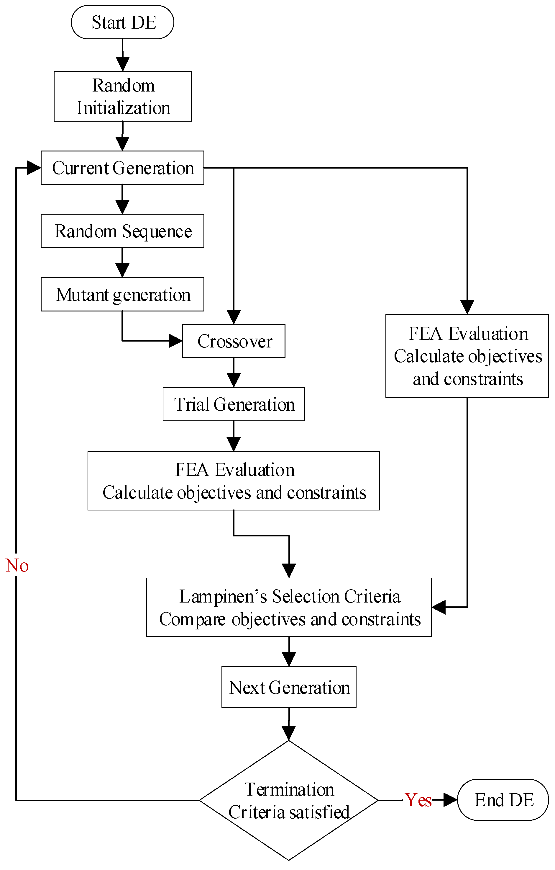
3.2. Optimization Algorithm and Procedure

As discussed in the last subsection, the current optimization problem comprises multiple design objectives as well as design constraints. As a result, a multi-objective design optimization algorithm must be employed to achieve the various objectives while satisfying all the constraints. Thus, a differential evolution (DE)-based multi-objective design optimization algorithm is implemented, and the flowchart of its implementation process is shown in Figure 6 [34]. As shown in the figure, the DE process primarily consists of initialization, mutation, crossover, and selection. The mutation and crossover process is utilized to generate a trial generation. The evaluations corresponding to the trial generation are then compared to the evaluations corresponding to the current generation during selection and used to obtain the next generation.
The optimization process involves coupling of two different software platforms—Matlab and Ansys Electronics. An optimization run requires a Matlab based script of the DE algorithm and three Ansys-based parametric models of the PMASynRM designs—one model for performance evaluation at 70 °C and two models for demagnetization analysis at −20 °C and 150 °C operating temperatures. The Matlab script first generates an initial randomized population for the various design variables within the defined limits. The set of values for the various design variables are then exported to Ansys Electronics for Finite Element Analysis (FEA)-based evaluations of various performance parameters. The FEA results corresponding to the each design variation are then imported back to Matlab for the selection of the best designs of the current generation based on the selection criteria and evolution of the next generation. The process is repeated for the defined number of generations, and the trade-off plots corresponding to the evaluated design candidates are obtained. The design candidates meeting the electromagnetic design criteria are subsequently subjected to mechanical stress analysis to evaluate their structural feasibility. The optimization analysis presented here is run for 25 generations with 30 populations in each generation.

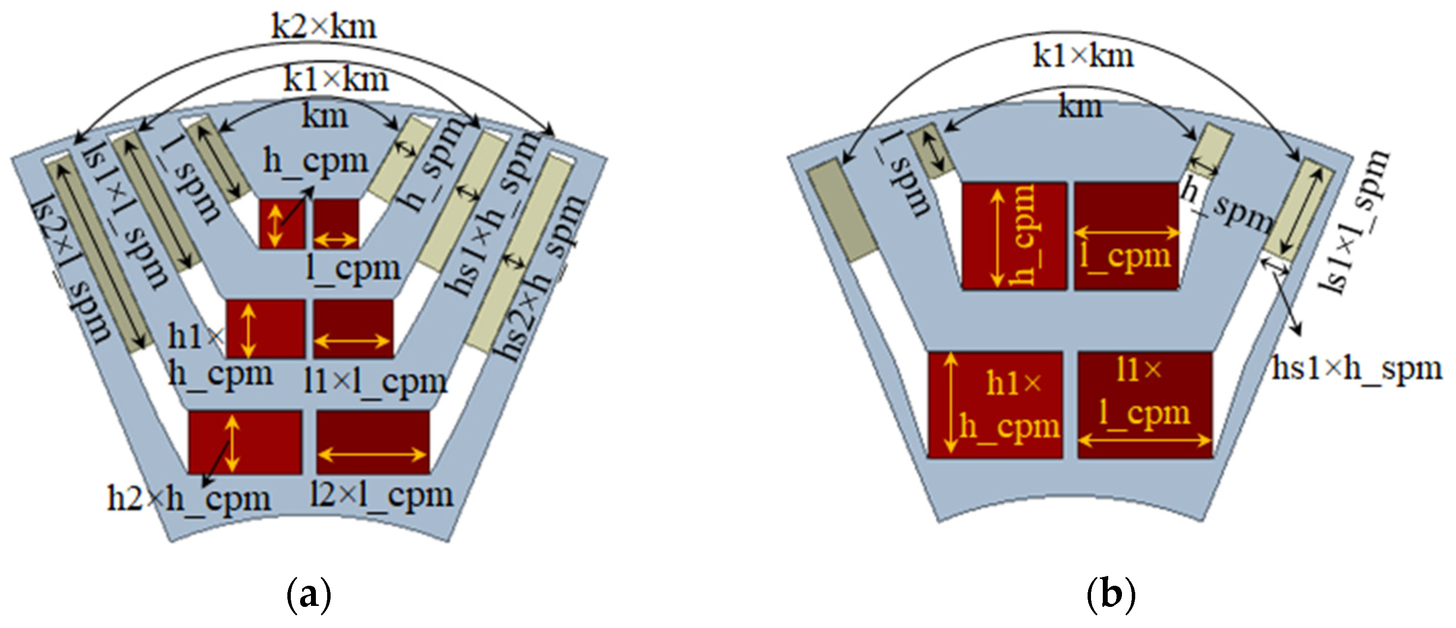
3.3. Optimization Parameters

As discussed earlier, since the design optimization employs the time-stepped FEA method, the design parameters used to prepare the FE model of the machine topologies can be directly utilized in the design optimization. The various design objectives and constraints of optimization defined earlier are mainly governed by the dimensions and positioning of different magnets present in the rotor structure. Based on this, the various design parameters that can be used to optimize the rotor designs of both three-layer and two-layer PMASynRM topologies are depicted in Figure 7a and Figure 7b, respectively. The ranges of variation for the design parameters of each PMASynRM topology are given in Table 3.

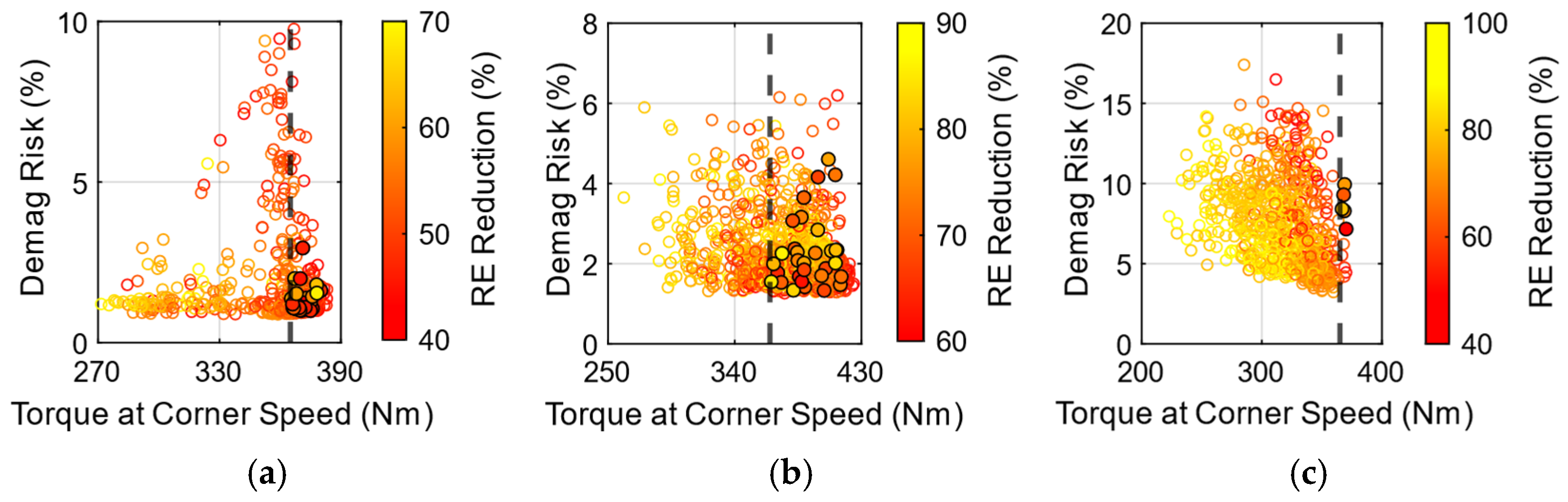
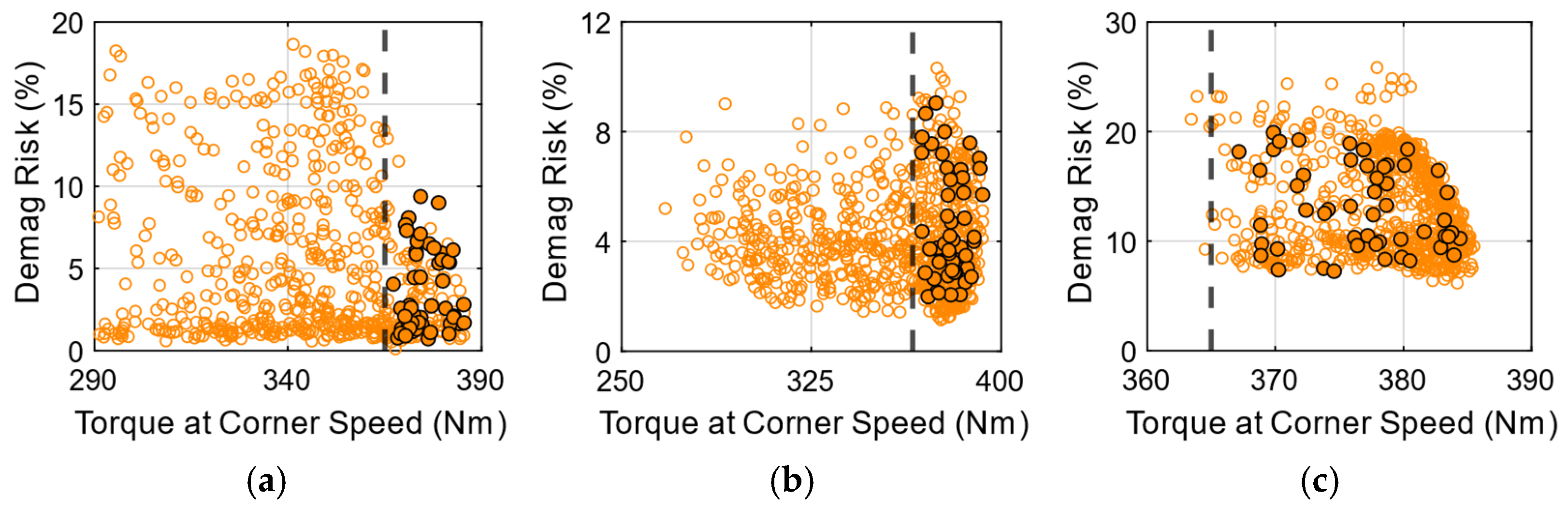
3.4. Trade-Off Plots

The simulation for the design optimization of various PMASynRM topologies with six magnet combinations was run using Matlab R2021a and Ansys Electronics Desktop 2022 R2 software platforms. The scatter plots corresponding to various PMASynRM designs plotted against the defined objectives and constraints of optimization were obtained from each optimization run and are illustrated in Figure 8, Figure 9, Figure 10, Figure 11, Figure 12 and Figure 13. The design points positioned to the right side of the dotted line in each plot represent the designs that fulfill the baseline torque requirements.

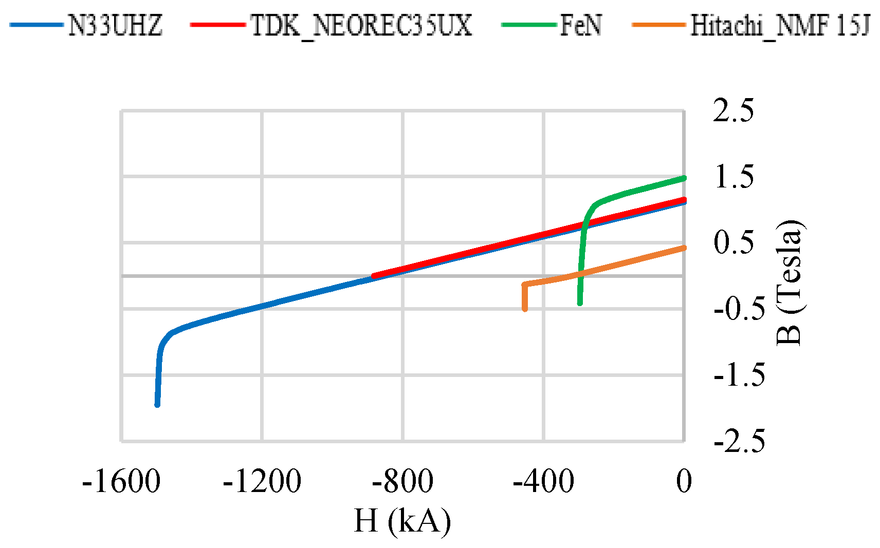
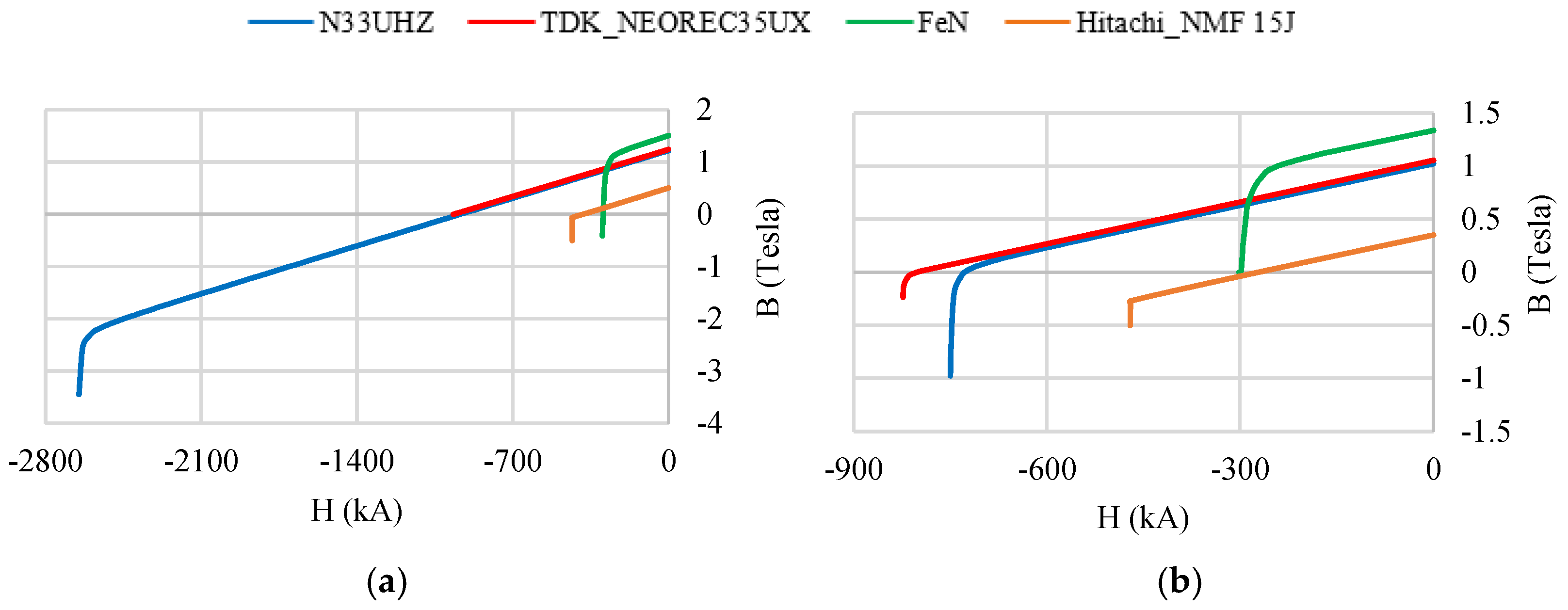
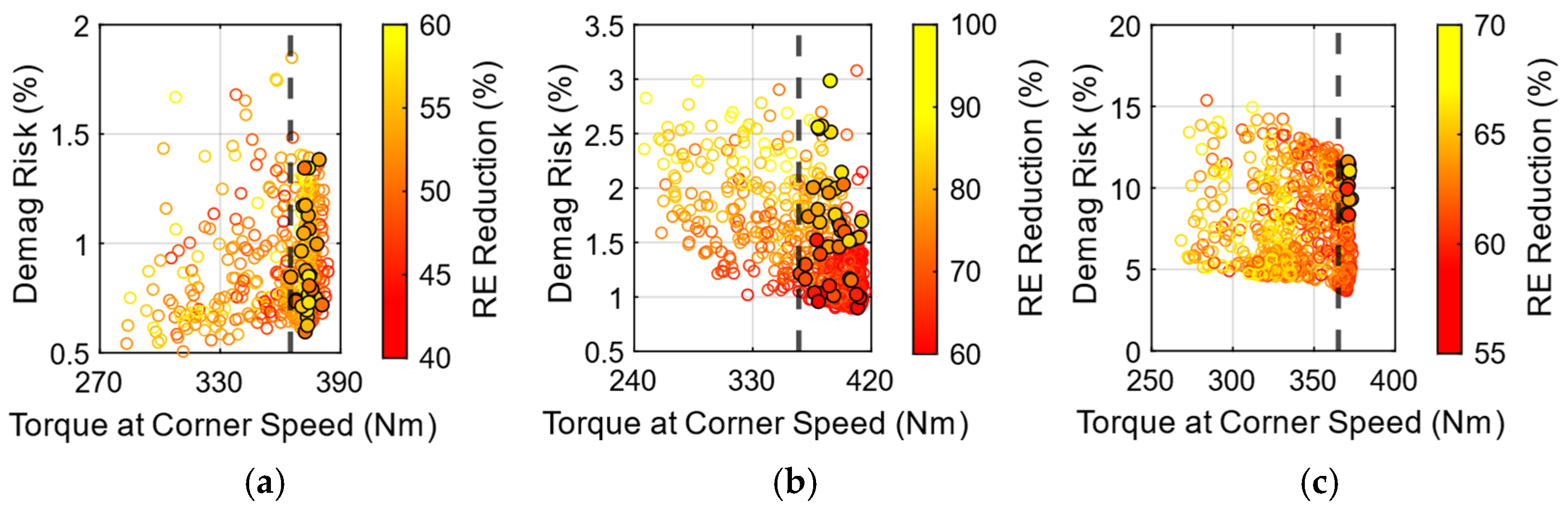
3.4.1. Rare-Earth and Iron Nitride Magnet Combinations

As mentioned in Table 2, the C1 and C2 magnet combinations consist of a combination of RE magnets with an RE-Free Iron Nitride magnet. The RE magnets selected for this combination include NdFeB magnets and Low-Dysprosium NdFeB magnets, both having comparable maximum energy products (BHmax). The trade-off plots for C1 and C2 magnet combinations for the three PMASynRM topologies are shown in Figure 8 and Figure 9, respectively. It can be observed from the plots that for both the magnet combinations, several designs are capable of attaining higher than the baseline torque requirement for all the discussed topologies. The lower the RE content reduction, the higher the torque output. This is obvious as high torque is observed in machines with RE magnets. On the other hand, a lower demagnetization risk is observed in designs having a lower RE reduction or a higher RE magnet volume. This trend is also expected as the RE magnets have a lower risk of demagnetization compared to RE-free magnets. Thus, a conflicting trend is observed, as selecting a design with a lower RE magnet volume may have a lower torque output as well as a higher risk of demagnetization. Since it is required to meet the target torque requirement with an acceptable level of demagnetization (below 5%), a compromise between a low RE content, high torque output, and low demagnetization risk can be made to select the best design candidate.
For the C1 magnet combination, it can be observed in Figure 8 that the majority of the designs meeting the baseline torque requirement fall in the range of a 40–60% RE reduction for a three-layer, eight-pole topology. Meanwhile, the two-layer, eight-pole and two-layer, six-pole designs are capable of achieving a 60–70% RE reduction. This is mainly because there is more space available to accommodate a larger volume of magnets in two-layer designs compared to three-layer designs. The demagnetization risk observed can be as high as 15% for various designs, although the feasible designs are concentrated below the 5% demagnetization risk level. The high demagnetization is expected due to the low remanence and second quadrant knee point of FeN magnets shown in Figure 3.
For the C2 magnet combination, a similar trend is observed for the RE magnet volume reduction, as the RE magnet used here has a similar remanence and energy product. Meanwhile, the demagnetization observed for various designs is below 3% for the eight-pole designs and around 5–10% for the six-pole designs. This can be due to a higher level of magnetic saturation in six-pole designs.
Figure 8. Trade-off plots for PMASynRM topologies with NdFeB and FeN magnets. (a) Three-layer, eight-pole design. (b) Two-layer, eight-pole design. (c) Two-layer, six-pole design.
Energies 17 01873 g008
Figure 9. Trade-off plots for PMASynRM topologies with Low-Dy NdFeB and FeN magnets. (a) Three-layer, eight-pole design. (b) Two-layer, eight-pole design. (c) Two-layer, six-pole design.
Energies 17 01873 g009

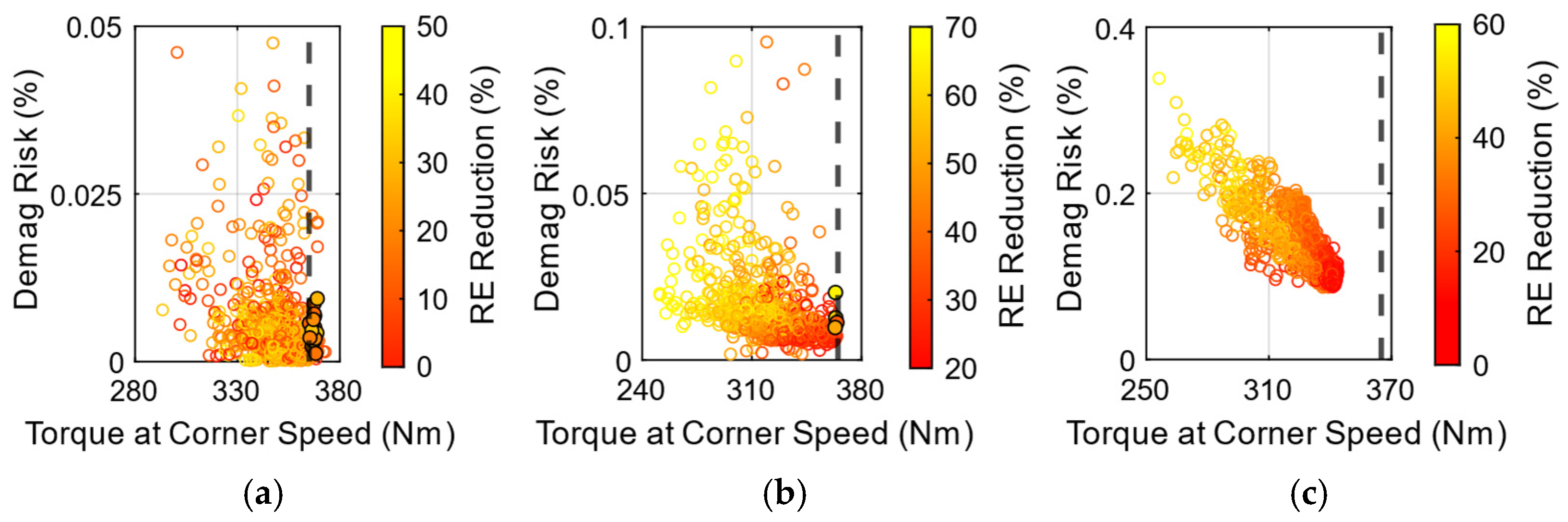
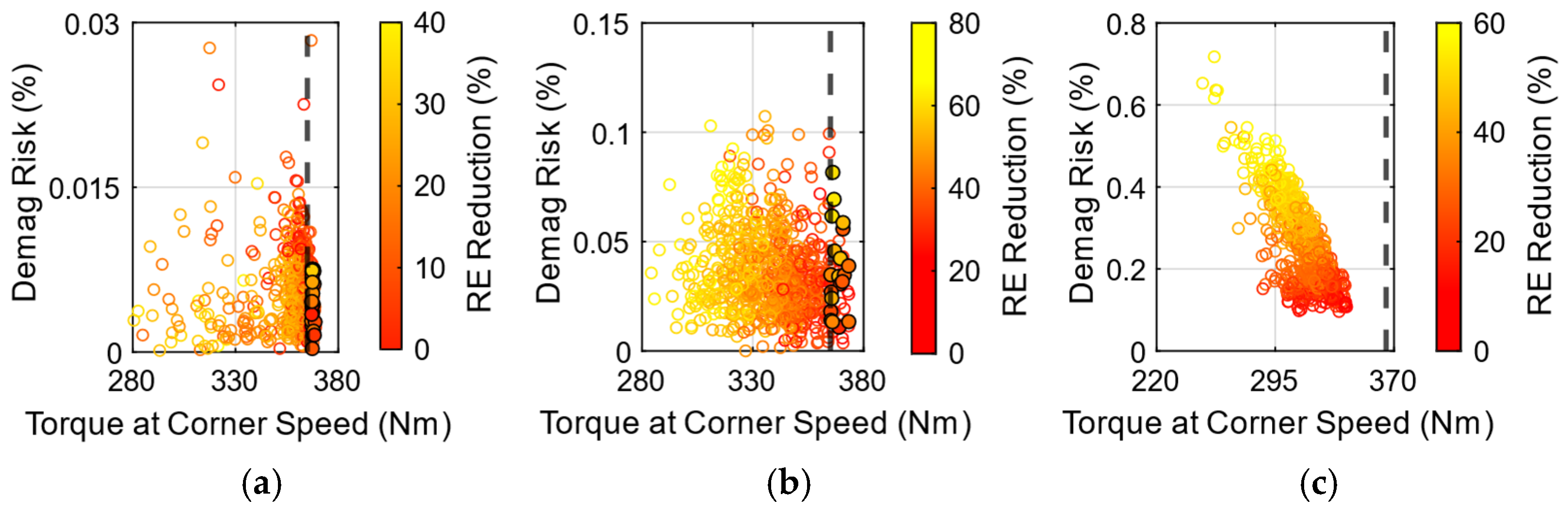
3.4.2. Rare-Earth and Ferrite Magnet Combinations

It can be observed in Figure 3 and Figure 4 that both the RE magnets as well as the ferrite magnet have knee points in the third quadrant. Hence, for these magnet combinations, the risk of demagnetization of magnets is significantly lower. However, due to the lower remanence of ferrite magnets, the torque output is also lower, leading to the usage of a higher volume of RE magnets in such designs to compensate for the torque reduction. This is evident in the trade-off plots for the Low-Dy NdFeB and ferrite (C3) magnet combination shown in Figure 10, as well as the plots for NdFeB and ferrite (C4) magnets shown in Figure 11. It can be observed in the figures that for the three-layer, eight-pole and two-layer, eight-pole topologies, the RE reduction for the feasible designs meeting the torque requirement is lower than 25%, while for the two-layer, six-pole topology, the designs are unable to meet the torque requirement, even with a higher volume of RE magnets. This can be attributed to the high level of magnetic saturation in the rotor core as a result of increased flux per pole in six-pole designs. Thus, for these magnet combinations, the criteria for the selection of the best design candidate is to obtain a design that can satisfy the baseline torque requirement and has the highest RE reduction.

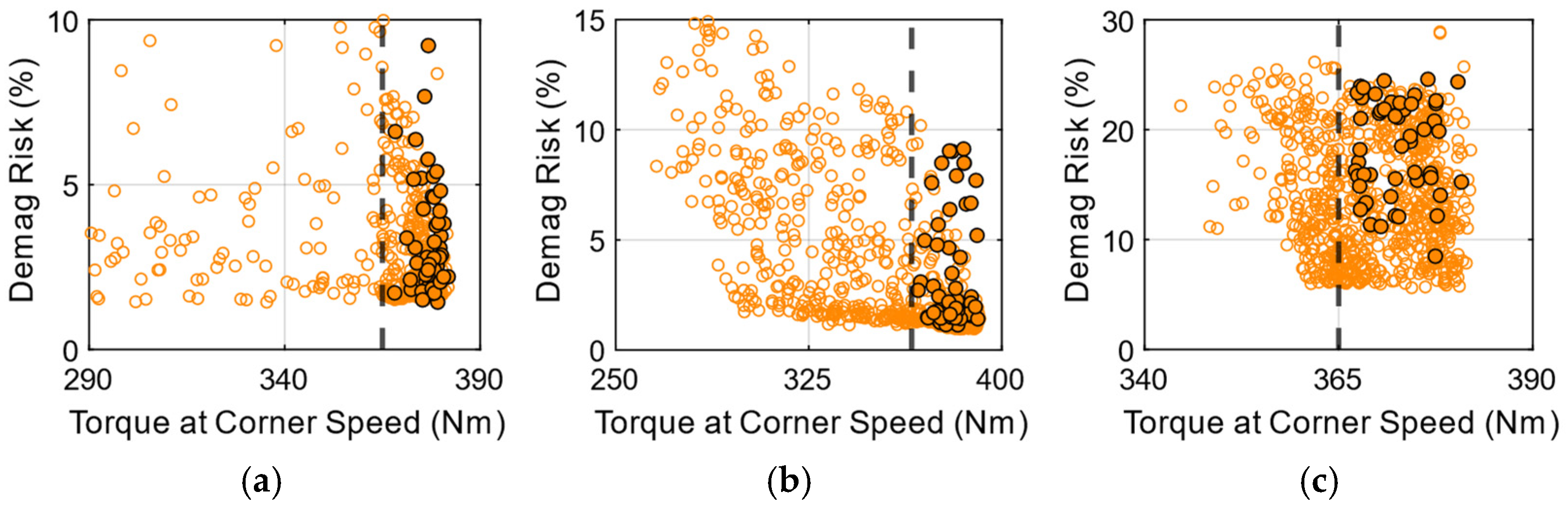
3.4.3. Rare-Earth-Free Magnet Combinations

The rare-earth-free magnets used here include ferrite and Iron Nitride magnets, as given in Table 2. The major demerit of RE-free magnets includes lower remanence and a high risk of demagnetization. Since the FeN magnets can provide a high remanence, as shown in Figure 3 and Figure 4, ferrite magnets experience low demagnetization risk, and the combination of the two magnets can be utilized to obtain RE-free PMASynRM designs. Also, due to high remanence, the FeN magnets can be used without blending with other magnets to obtain RE-free designs, as represented by the C6 combination in Table 2.
Figure 12 shows the trade-off plots for the ferrite and FeN (C5) magnet combination, and Figure 13 shows the plots for PMASynRM design using FeN magnets only (C6). Since these designs are already free from rare-earth materials, the RE reduction objective is not applicable to these magnet combinations. As a result, the demagnetization risk is plotted against torque at the corner speed for these combinations. It can be observed in the plots that several designs are possible that can meet the baseline torque criteria across all the topologies. Also, the designs having the highest torque can be observed to have the lowest risk of demagnetization. This trend is consistent for both C5 and C6 magnet combinations across all three topologies. This is possible due to the use of thicker magnets, which contributes to high torque and low Demag in such designs. Thus, for the selection of the best design candidate, the designs having minimum demagnetization risk and attaining the desired torque can be considered as the most optimum design.
Figure 10. Trade-off plots for PMASynRM topologies with Low-Dy NdFeB and ferrite magnets. (a) Three-layer, eight-pole design. (b) Two-layer, eight-pole design. (c) Two-layer, six-pole design.
Energies 17 01873 g010
Figure 11. Trade-off plots for PMASynRM topologies with NdFeB and ferrite magnets. (a) Three-layer, eight-pole design. (b) Two-layer, eight-pole design. (c) Two-layer, six-pole design.
Energies 17 01873 g011
Figure 12. Trade-off plots for PMASynRM topologies with ferrite and FeN magnets. (a) Three-layer, eight-pole design. (b) Two-layer, eight-pole design. (c) Two-layer, six-pole design.
Energies 17 01873 g012
Based on the discussed criteria used for the selection of the best design candidates for each magnet combination, the optimum design for the various PMASynRM topologies can be obtained. As indicated by the trade-off plots, several feasible designs for each topology may exist. However, there is a possibility that designs found to be electromagnetically feasible may not meet the mechanical feasibility criteria. Therefore, the feasible design candidates for each topology and magnet combination must undergo mechanical stress evaluations.
Figure 13. Trade-off plots for PMASynRM topologies with FeN magnets. (a) Three-layer, eight-pole design. (b) Two-layer, eight-pole design. (c) Two-layer, six-pole design.
Energies 17 01873 g013

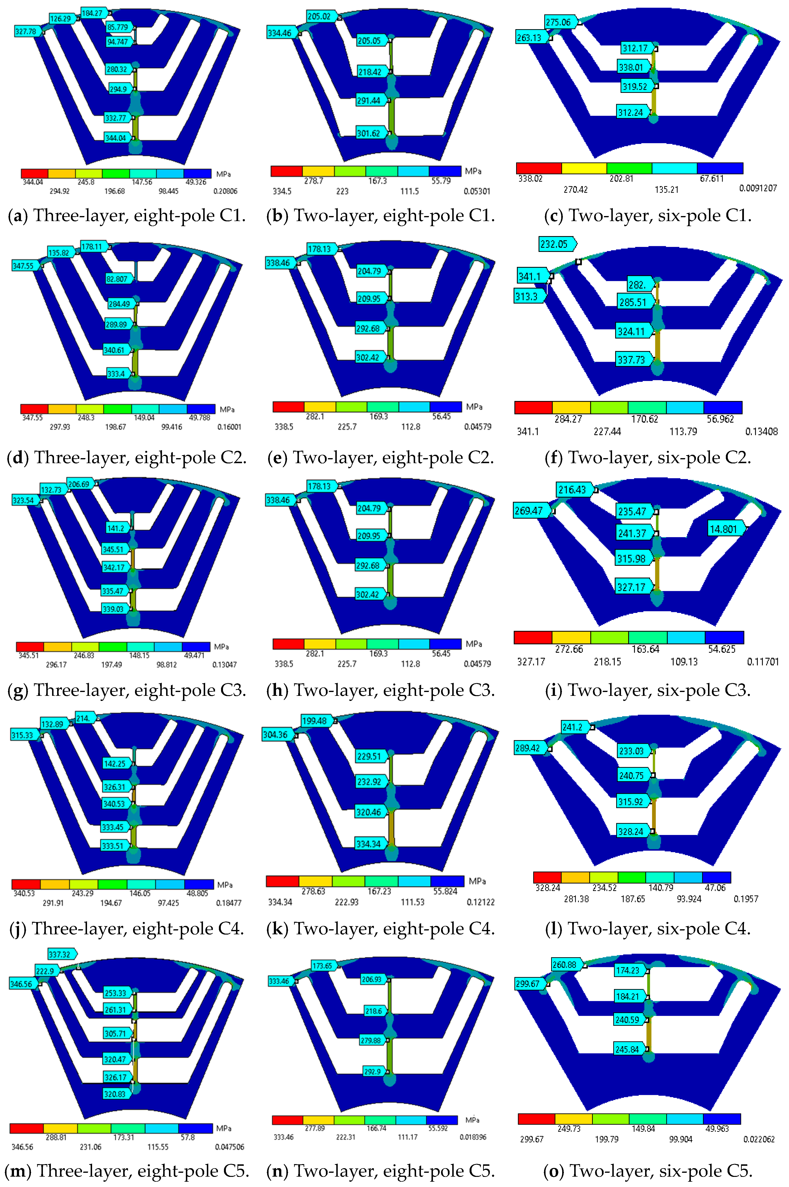
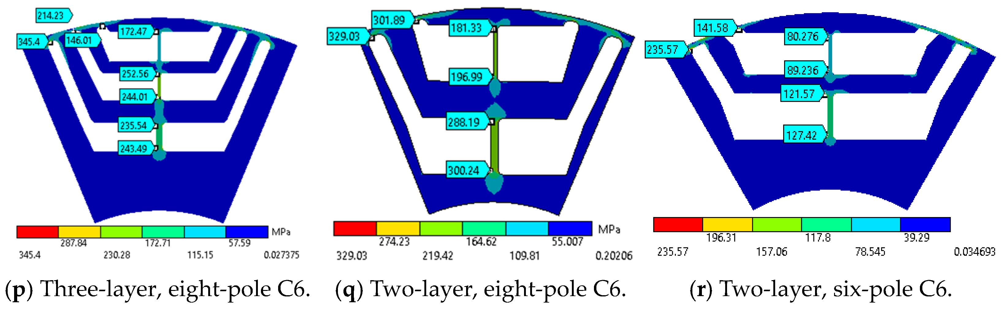
3.5. Mechanical Stress Analysis

As discussed earlier, various electromagnetically feasible designs, which are capable of achieving the design objectives while satisfying the constraints, were obtained from the electromagnetic design optimization of each topology and magnet combination. Nevertheless, it is essential to assess their structural feasibility to prevent failure due to excessive stress since they are intended to operate at speeds of up to 9000 rpm. Therefore, the rotor laminations of various feasible designs of each magnet combination are subjected to mechanical stress analysis.
The mechanical stress analysis of various designs was performed using Ansys Workbench 2022 R2 software. The analysis was performed at an operating speed of 10,000 rpm, considering a safety factor of 1.2 on the maximum speed [14]. The contact surface between the rotor lamination and magnets is assumed to have frictional contact with a contact coefficient of 0.2. The global mesh element size and the magnet mesh size are taken as 0.5 mm and 0.3 mm, respectively. An edge sizing of 0.1 mm is used for accurate meshing of the curve’s edges. It is required to maintain the maximum equivalent von Mises stress developed in the rotor lamination below the material yield strength (350 MPa) at a maximum operating speed of 10,000 rpm. A safety factor of 1.05 on the lamination material yield strength was also assumed [14].
Among the various electromagnetically feasible design candidates, those that could sustain their structural integrity under the mentioned operating conditions were chosen as the mechanically feasible designs and are marked with a black outline in Figure 8, Figure 9, Figure 10, Figure 11, Figure 12 and Figure 13. Among these designs, the optimal design candidates were selected based on the selection criteria described for each magnet combination in Section 3.4. The equivalent von Mises stress developed in the rotor laminations of the selected design candidates for each topology and magnet combinations are depicted in Figure 14. It can be observed in the figures that the rotor laminations of all the selected designs have maximum stress below 350 MPa. The stresses in various designs are mainly concentrated around the center posts and bridges of the outer flux barrier layers. The mechanically feasible designs are subsequently utilized for further evaluations of various performance parameters.

3.6. Design Optimization Performance

The performance of a design optimization method can be assessed by evaluating parameters such as the complexity of the method employed, accuracy, computational cost, as well as computational time. As mentioned earlier, the discussed method makes direct use of the design parameters used in the FE modeling of the machine for its design optimization. Since the geometric modeling of a machine is relatively simpler compared to the analytical or response surface modeling discussed earlier, the discussed method can be inferred as fairly straightforward. Moreover, the mechanical stress in the rotor laminations can also be analyzed using the same FE model, as the Ansys software facilitates seamless coupling of various Multiphysics simulation platforms. Also, the FE-based simulation results are widely accepted as the most accurate analysis, as it involves solving the mathematical equations using numerical techniques to converge to a solution. The other optimization methods use approximate geometry modeling techniques, which may lead to reduced solution accuracy [17,18,19,20,21,22,23,24,25,26,27,28]. However, the presented method requires relatively higher computational power and time for performing design optimization, a requirement that escalates with the increase in the number of FEA-based performance parameters utilized in the optimization process. However, with the advancement in technology, high-performance computing devices and simulation software featuring parallel processing capability are readily available nowadays at moderate expenses, which can significantly reduce computational time. A performance comparison of various optimization methods is presented in Table 4.

4. Performance Analysis and Comparison

Although the electromagnetically feasible design candidates for various rotor topologies obtained after design optimization and shown in the trade-off plots are supposed to satisfy the torque and terminal voltage requirements, there is a possibility that some designs may violate the defined criteria at higher speeds. This may be due to the use of data interpolation to calculate the higher speed torque and terminal voltages in the design optimization process, as discussed in Section 3.1. Additionally, as mentioned earlier, none of the six-pole designs with ferrite magnet combinations could meet the baseline torque requirement, so the best available designs were selected for these magnet combinations. Hence, in order to ensure that the selected designs met all the specified design requirements across the entire operating range, the specific design candidates for each topology and magnet combination were subjected to several performance checks. This section presents the evaluation of various performance parameters for the best design candidates, which include torque/power versus speed characteristics, torque ripple, efficiency maps, and demagnetization analysis.

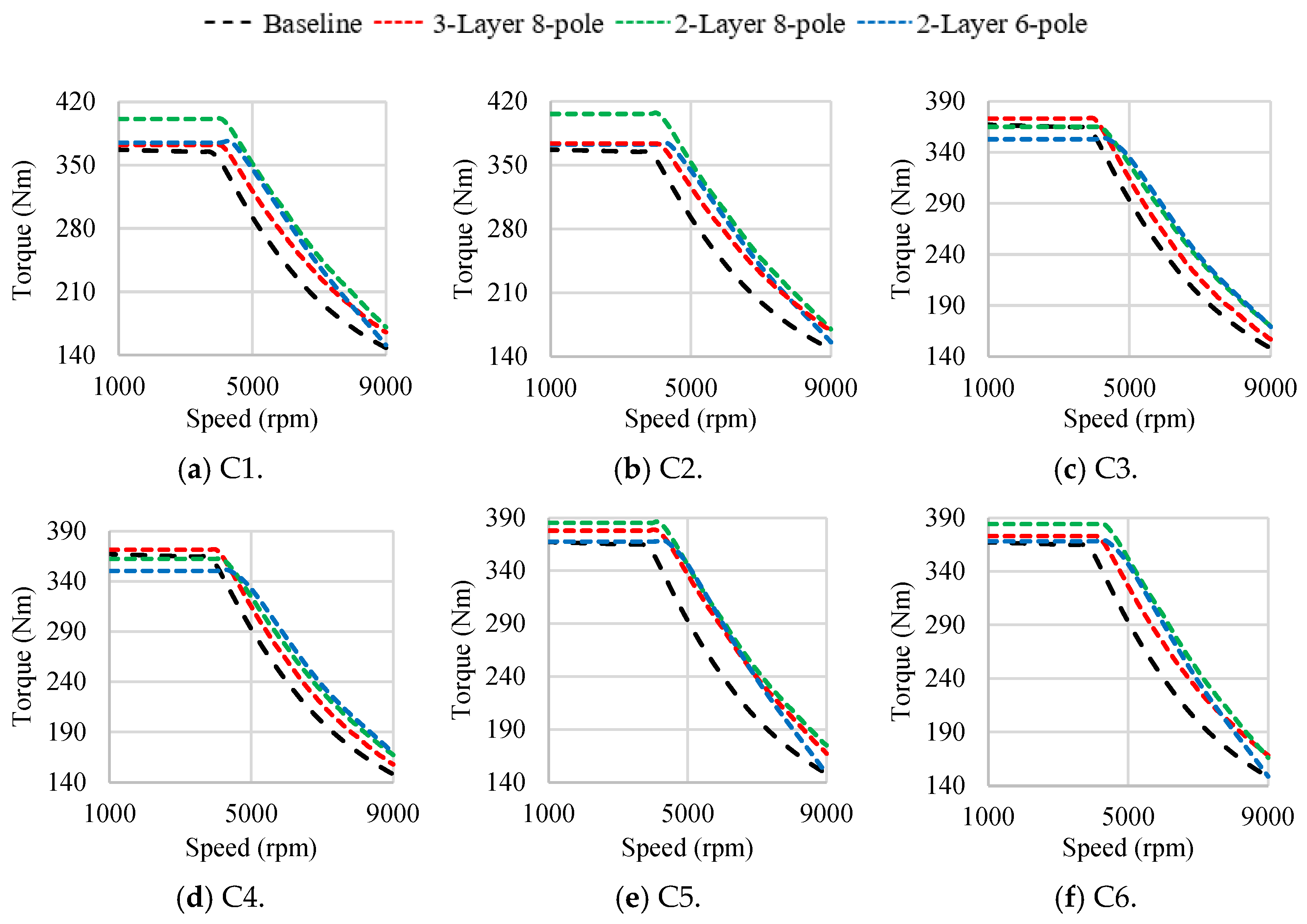
4.1. Torque–Speed Characteristics

The mechanically feasible design candidates for various PMASynRM topologies with different magnet combinations were evaluated for torque output at various operating speeds using transient FE-based simulations on Ansys Electronics. The simulations were performed at a normal operating temperature of 70 °C using a peak load current of 400 ARMS up to 5000 rpm, 385 ARMS at 7000 rpm, and 351 ARMS at 9000 rpm, as defined by the current limit of the Chevy Bolt motor at different operating speeds. Since it is also required to maintain the terminal voltage within the maximum permissible limit based on 350 V DC bus voltage, the current angle at each operating speed was varied to obtain the torque–speed characteristics of various designs.
The torque speed characteristics for each magnet combination for three-layer, eight-pole; two-layer, eight-pole; and two-layer, six-pole PMASynRM topologies are compared in Figure 15. It can be observed in the figures that among all the designs, the two-layer, eight-pole designs show the highest torque–speed envelope for the designs using the Iron Nitride magnet combination. This is because of the higher remanence of FeN magnets as well as more space available in two-layer designs to accommodate a larger magnet volume. However, this phenomenon is not observed in the case of two-layer, six-pole designs. This is mainly because the reduction in the number of poles from eight to six causes an increase in the flux per pole, leading to magnetic saturation of the rotor core, thus resulting in reduced torque for six-pole designs. For the designs utilizing ferrite magnet combinations, the three-layer designs have the highest torque up to the base speed. This can be attributed to the higher contribution of reluctance torque as well as the larger volume of the RE magnet used in three-layer designs compared to two-layer, eight-pole designs, as given in Table 5. For six-pole designs, due to the saturation of the rotor core, the increased usage of the RE magnet volume does not contribute to a proportional increment in torque. It is also worth mentioning that all the selected design candidates, except C3 and C4 combinations of two-layer, six-pole topology, are able to match or exceed the baseline torque across the entire operating speed range. At speeds above corner speed, all designs exceed the baseline torque limit as a result of better flux weakening capability at higher speeds. This can be attributed to the characteristic current of all designs being lower than the rated motor current, in addition to the low coercivity of the RE-free magnets used in various designs, as shown in Figure 4b. The torque values of various designs at the four operating speeds are compared in Table 5.

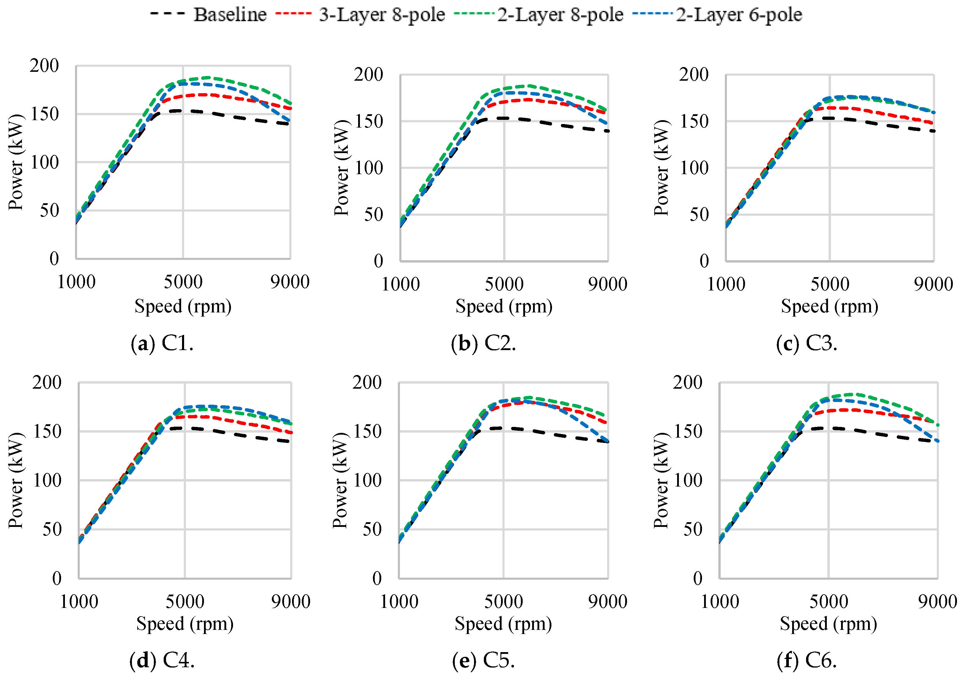
4.2. Power–Speed Characteristics

Figure 16 shows the comparison of the power–speed characteristics of the best design candidates for various PMASynRM topologies for each magnet combination. It can be observed in the plots that all the selected designs have a power capability higher than the baseline design. This can be attributed to the characteristic current of all designs being lower than or close to their peak current rating, as given in Table 5. This suggests that the designs are capable of operating at constant power over a wide speed range. Among various PMASynRM designs, the two-layer, eight-pole designs enabled with Iron Nitride magnets show the highest power capability.

4.3. Torque Ripple

The torque ripple for the various design candidates selected earlier was calculated using FEA transient simulation at the same operating conditions used for the torque calculation. The calculated values for various designs are compared in Table 5. It can be observed that the torque ripple for three-layer designs is higher than that for two-layer designs. This is mainly because of a higher reluctance offered by the three layers of flux barriers in the case of three-layer designs.

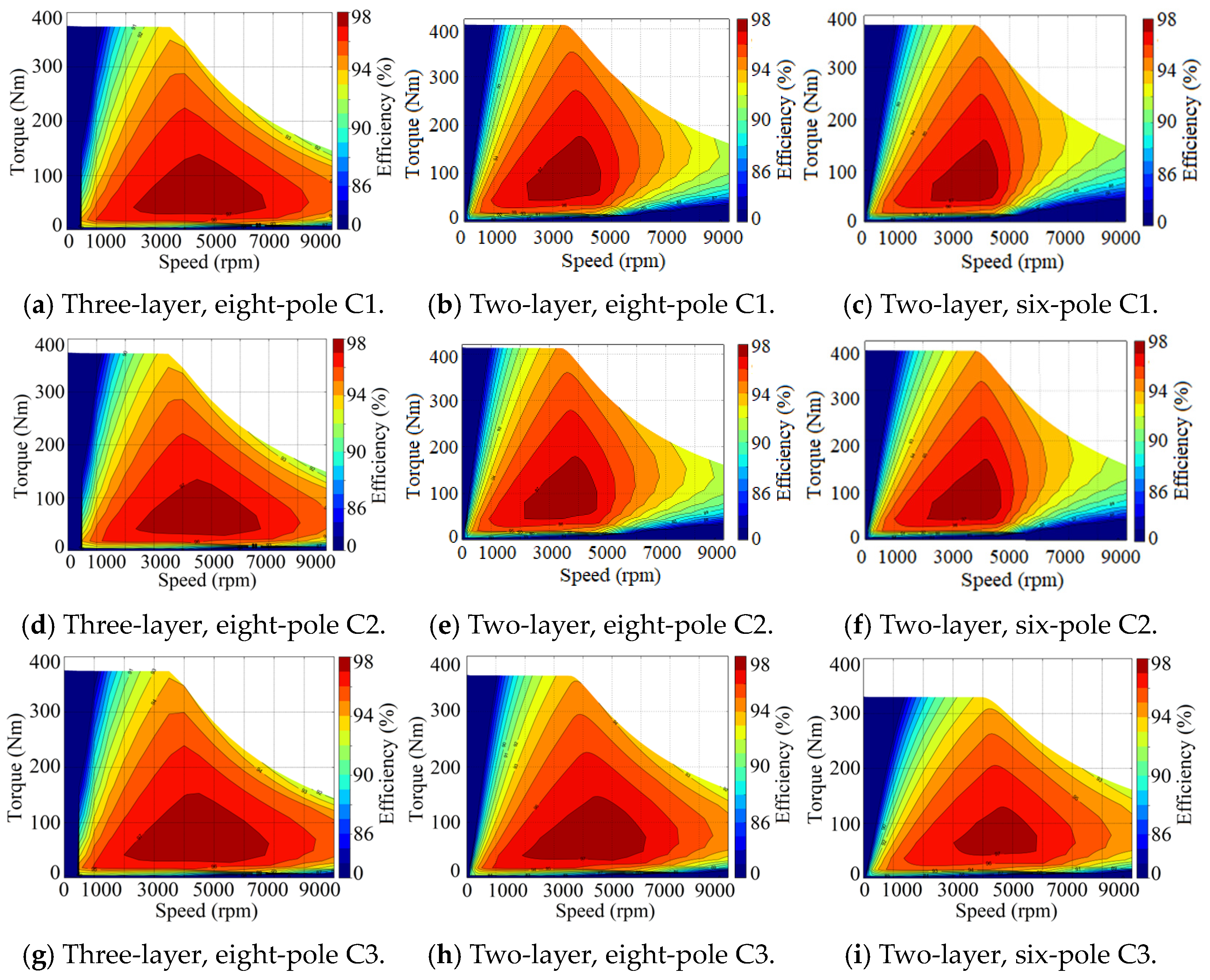
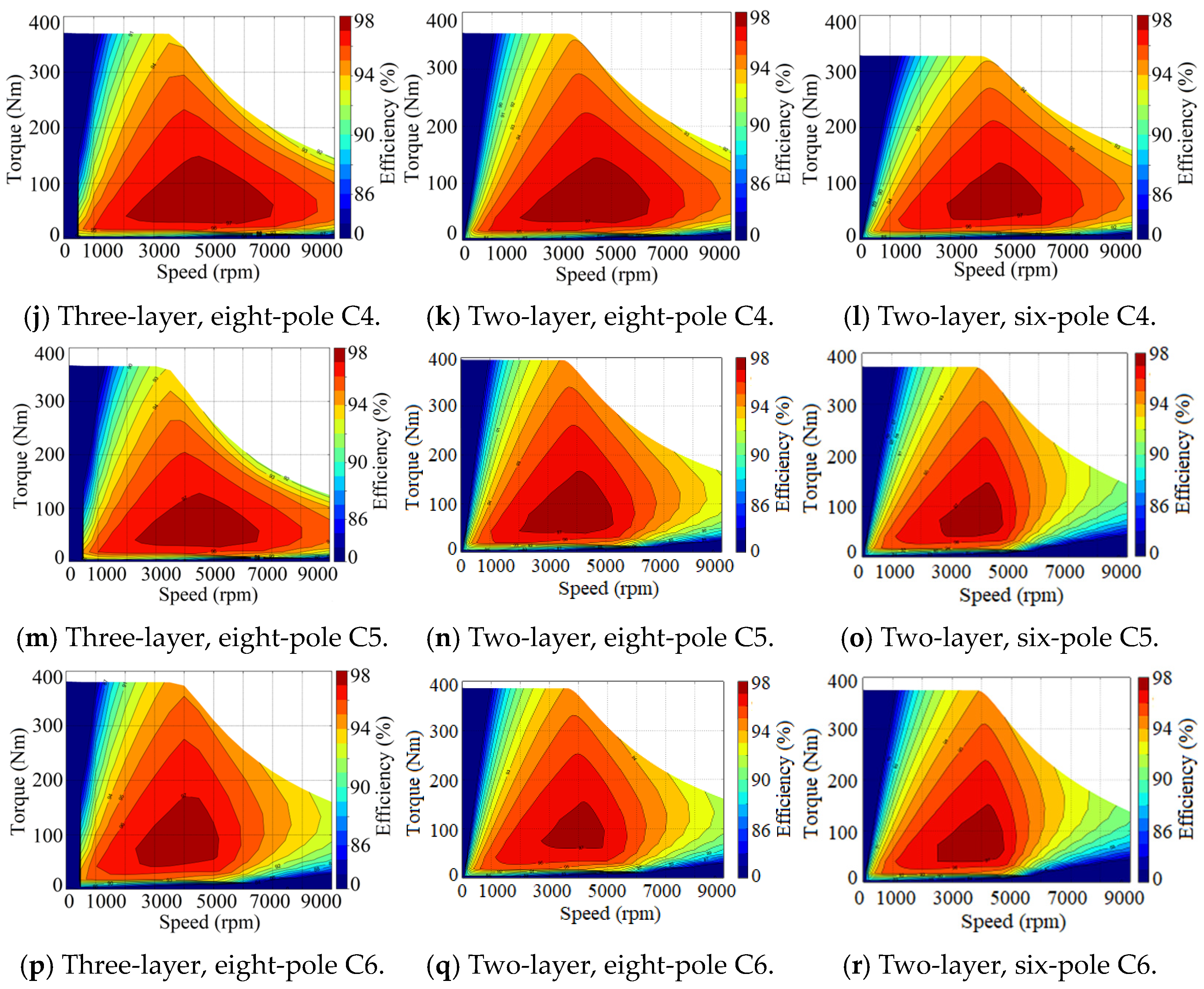
4.4. Efficiency Maps

To evaluate the high-speed performance of various PMASynRM designs, the FEA models were prepared for each design on the Ansys Motor-CAD platform. The stator design and winding configuration were prepared in Motor-CAD, while the rotor geometry for individual PMASynRM designs were imported from Ansys models corresponding to each design. The FE models were analyzed, and the efficiency maps for each magnet combination of various PMASynRM topologies were obtained, as depicted in Figure 17.
It can be observed from various plots that among two-layer designs, the designs enabled with FeN magnet combination, i.e., C1, C2, C5, and C6, have lower efficiency at higher speeds compared to the designs using ferrite magnet combinations. This can be attributed to the higher remanence of FeN magnets with respect to ferrites, resulting in a higher d-axis current requirement for flux weakening at higher speeds. This leads to increased losses and hence lower efficiency at higher speeds for such designs. However, their three-layer counterparts for the same magnet combination show higher efficiency at higher speeds. The reason for this can be the use of a reduced mass of FeN magnets in three-layer designs compared to two-layer designs, as evident in Table 5, thus resulting in lower flux density and hence better flux weakening capability and higher efficiency at higher speeds.

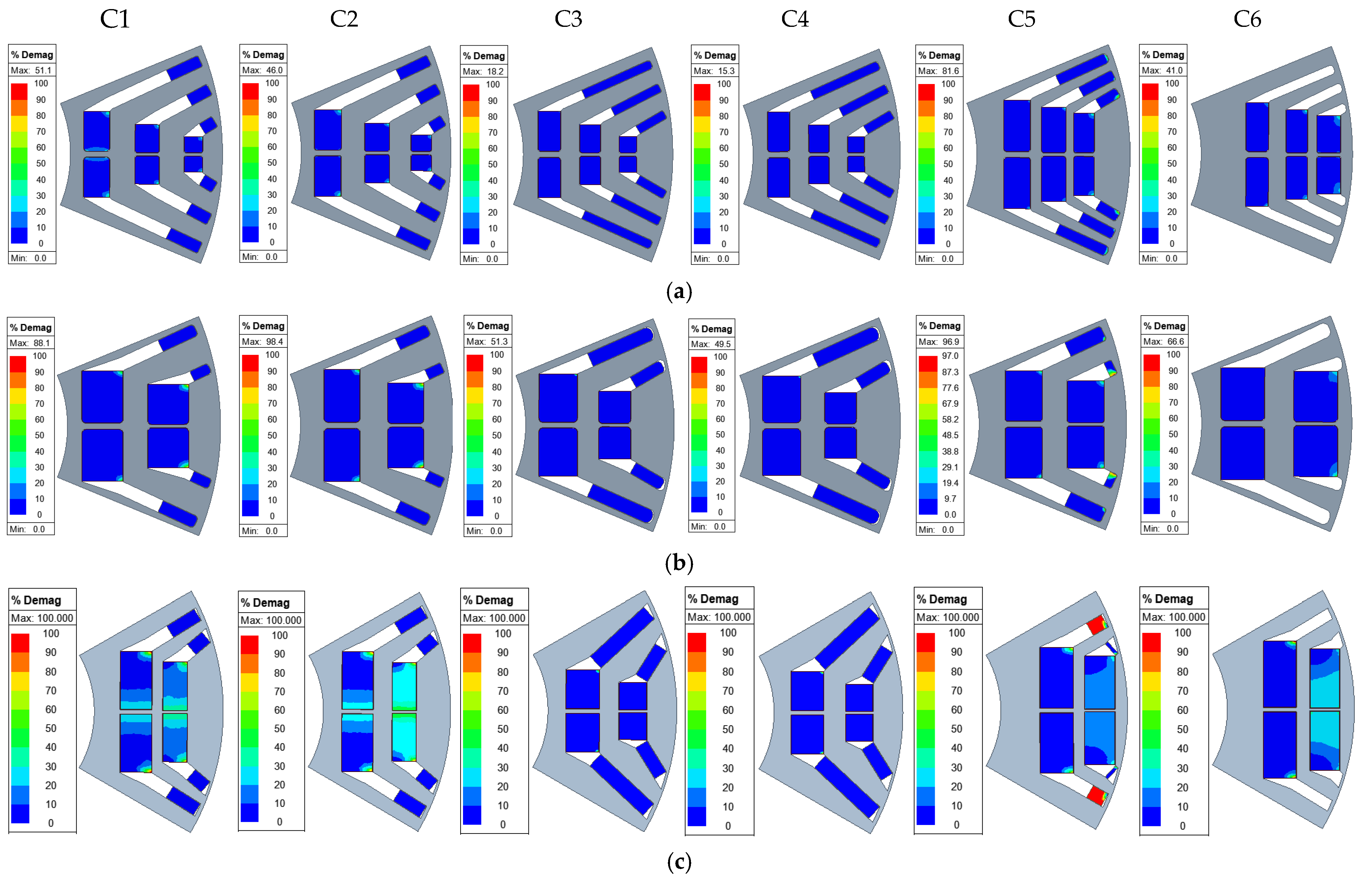
4.5. Demagnetization Analysis

As discussed in [14,35], two methods were investigated for the demagnetization analysis of PMASynRM designs. The first method is based on the calculation of the net reduction in the no-load back-EMF after injecting peak load current along the negative d-axis, as defined by Equation (7). This method gives an insight into the global impact of demagnetization on motor performance, as mentioned earlier. The minimization of this parameter was implemented as an objective in the optimization algorithm. Consequently, the designs achieving a minimum reduction in back EMF, in addition to satisfying the other objectives and constraints, were selected as the best design candidates for various topologies.
However, a quantitative analysis of the back EMF reduction achieved for each of the selected design candidates was not presented. Therefore, the percentage of reduction in the no-load back EMF occurring due to the demagnetization of magnets was re-evaluated at −20 °C and 150 °C operating temperatures. The corresponding values for the various design candidates are quantitively compared in Table 5 and visually highlighted in Figure 18. It can be observed that the six-pole designs experience the highest back EMF reduction or risk of demagnetization. This is mainly because of the saturation of the rotor core as a result of increased flux density owing to lower number of poles. Due to saturation, the permeability of rotor iron decreases, impeding the magnetic flux through it. Thus, the demagnetizing armature current aligned against the magnet d-axis causes intensified demagnetization of magnets, as the magnet flux cannot be diverted to a low reluctance path. Among various eight-pole designs, the designs utilizing FeN magnet combinations experience higher demagnetization. This is expected due to low coercivity and second-quadrant knee points of FeN magnets, as mentioned earlier.
Another method used for analyzing the demagnetization of magnets is based on the calculation of the percentage demagnetization of magnet surfaces using Equation (10) and can be interpreted as a color map plot over the individual magnet surfaces. Such plots are obtained for the selected design candidates of each topology and magnet combination, as illustrated in Figure 19. Since the majority of the designs experience relatively higher demagnetization at a −20 °C operating temperature, the plots are obtained for that temperature only. These plots visually quantify the local areas of magnets where demagnetization is occurring. It can be observed in the figures that the six-pole designs experience a significantly high level of demagnetization, which is consistent with the results obtained using the EMF method, as shown in Figure 18.
D = 1 B m a g n e t B r e s i d u a l × 100

4.6. Cost Assessment

As discussed earlier, since the stator of the PMASynRM designs is the same as the baseline design, the motor cost will be decided primarily by the total cost of magnets used in each design. Thus, an approximate cost assessment of the best design candidates for each magnet combination based on the cost/kg and mass of the RE and RE-free magnets used in each design was obtained. The cost of RE magnet materials, i.e., NdFeB and DyFree, is taken as USD 70/kg, while the cost of ferrite and FeN magnets were assumed to be USD 10/kg and USD 30/kg, respectively. To calculate the mass of the RE and RE-free magnets in each design, a mass density of 7500 kg/m3 was taken for RE magnets. For ferrite and FeN magnets, the mass density was set to 5000 kg/m3 and 5300 kg/m3, respectively.
Based on the above assumptions, the total mass and cost of the magnets used in the optimized designs are calculated and summarized in Table 5. It is interesting to note that although the three-layer designs show inferior performance compared to their two-layer counterparts, the cost of the three-layer designs for each magnet combination is lower than that of the two-layer designs. This is primarily due to the large size of FeN magnets used in the two-layer designs, as depicted in Figure 19b,c, which adds to the magnet weight and hence the overall cost of the two-layer designs. Among the various three-layer and two-layer designs, C5 and C6, with RE-free magnet combinations, offer the most economical option, with up to 51% lower cost compared to the baseline design.

5. Conclusions

A three-layer, U-shaped PMASynRM topology enabled with a combination of four combinations of rare-earth and rare-earth-free magnets and two combinations of rare-earth-free magnets was suggested as a cost-effective solution for EV application. The topology was modified to obtain a design with an inherently lower risk of demagnetization and extended to two-layer designs with eight-pole and six-pole variations. The three PMASynRM topologies with six magnet combinations were optimized to minimize the volume of RE magnets as well as the demagnetization risk of magnets while attaining the baseline torque and terminal voltage requirements. A refined DE optimization algorithm, incorporating improved selection criteria along with modified design constraints and objectives, was employed to improve the solution convergence. The trade-off plots obtained from the optimization were utilized to filter out the electromagnetically feasible designs, which were then subjected to mechanical stress evaluation to ensure their structural integrity. The optimal design candidates selected from various mechanically feasible design points for each topology and magnet combination were subjected to a comprehensive performance evaluation aimed at identifying various trade-offs and determining the most suitable design topology. The comparative analysis of various designs revealed that the two-layer, eight-pole designs demonstrate superior performance compared to their three-layer, eight-pole and two-layer, six-pole counterparts in terms of attaining better torque/power speed characteristics and lower demagnetization risk with a reduced usage of RE magnets. In contrast, three-layer, eight-pole designs exhibit higher efficiency at elevated speeds and a lower total weight of magnets, contributing to an economical design. Thus, a compromise between cost and performance is necessary to select the optimal PMASynRM topology. The proposed method has the potential to further reduce the computational time by decreasing the number of FE models required in the evaluation of performance parameters at different operating temperatures. Additionally, design parameters based on mechanical stress optimization can be introduced in the design optimization process. Furthermore, similar to the mechanical stress analysis, the optimization method can also be coupled with FE-based thermal and modal analysis in the future.

Author Contributions

Methodology, P.K. and R.W.; formal analysis, P.K. and R.W.; resources, A.E.-R.; data curation, P.K. and R.W.; writing—original draft preparation, P.K.; writing—review and editing, A.E.-R.; supervision, A.E.-R.; project administration, A.E.-R.; funding acquisition, A.E.-R. All authors have read and agreed to the published version of the manuscript.

Funding

This material is based upon work supported by the U.S. Department of Energy’s Office of Energy Efficiency and Renewable Energy (EERE) under the Advanced Vehicle Technologies Office Award Number DE-EE0009190.

Data Availability Statement

The original contributions presented in the study are included in the article, further inquiries can be directed to the corresponding author.

Conflicts of Interest

The authors declare no conflict of interest.

References

  1. Guglielmi, P.; Boazzo, B.; Armando, E.; Pellegrino, G.; Vagati, A. Permanent-Magnet Minimization in PM-Assisted Synchronous Reluctance Motors for Wide Speed Range. IEEE Trans. Ind. Appl. 2013, 49, 31–41. [Google Scholar] [CrossRef]
  2. Ferrari, M.; Bianchi, N.; Fornasiero, E. Analysis of Rotor Saturation in Synchronous Reluctance and PM-Assisted Reluctance Motors. IEEE Trans. Ind. Appl. 2015, 51, 169–177. [Google Scholar] [CrossRef]
  3. Obata, B.M.; Morimoto, S.; Sanada, M.; Inoue, Y. Performance of PMASynRM with Ferrite Magnets for EV/HEV Applications Considering Productivity. IEEE Trans. Ind. Appl. 2014, 50, 2427–2435. [Google Scholar] [CrossRef]
  4. Hofer, M.; Schrödl, M. Investigation of Permanent Magnet assisted Synchronous Reluctance Machines for Traction Drives in High Power Flux Weakening Operation. In Proceedings of the 2020 IEEE Transportation Electrification Conference & Expo (ITEC), Chicago, IL, USA, 23–26 June 2020; pp. 335–339. [Google Scholar]
  5. Barcaro, M.; Bianchi, N. Interior PM Machines Using Ferrite to Replace Rare-Earth Surface PM Machines. IEEE Trans. Ind. Appl. 2014, 50, 979–985. [Google Scholar] [CrossRef]
  6. Cai, H.; Guan, B.; Xu, L. Low-Cost Ferrite PM-Assisted Synchronous Reluctance Machine for Electric Vehicles. IEEE Trans. Ind. Electron. 2014, 61, 5741–5748. [Google Scholar] [CrossRef]
  7. Du, Z.S.; Lipo, T.A. Cost-Effective High Torque Density Bi-Magnet Machines Utilizing Rare Earth and Ferrite Permanent Magnets. IEEE Trans. Energy Convers. 2020, 35, 1577–1584. [Google Scholar] [CrossRef]
  8. Du, Z.S.; Lipo, T.A. Interior permanent magnet machines with rare earth and ferrite permanent magnets. In Proceedings of the 2017 IEEE International Electric Machines and Drives Conference (IEMDC), Miami, FL, USA, 21–24 May 2017; pp. 1–8. [Google Scholar]
  9. Ma, Q.; El-Refaie, A.; Lequesne, B. Low-Cost Interior Permanent Magnet Machine with Multiple Magnet Types. IEEE Trans. Ind. Appl. 2020, 56, 1452–1463. [Google Scholar] [CrossRef]
  10. Won, H.; Hong, Y.-K.; Choi, M.; Bryant, B.; Platt, J.; Choi, S. Cost-Effective Hybrid Permanent Magnet Assisted Synchronous Reluctance Machine for Electric Vehicle. In Proceedings of the 2021 IEEE International Electric Machines & Drives Conference (IEMDC), Hartford, CT, USA, 17–20 May 2021; pp. 1–6. [Google Scholar]
  11. Wu, W.; Zhu, X.; Quan, L.; Du, Y.; Xiang, Z.; Zhu, X. Design and analysis of a hybrid permanent magnet assisted synchronous reluctance motor considering magnetic saliency and PM usage. IEEE Trans. Appl. Supercond. 2018, 28, 5200306. [Google Scholar] [CrossRef]
  12. Ma, Q.; EL-Refaie, A.; Fatemi, A.; Nehl, T. Comparative Analysis of Two Different Types of Blended Permanent Magnet Assisted Synchronous Reluctance Machine. In Proceedings of the 2021 IEEE Energy Conversion Congress and Exposition (ECCE), Vancouver, BC, Canada, 10–14 October 2021; pp. 4189–4196. [Google Scholar]
  13. Ma, Q.; Ayman, E.R.; Fatemi, A. Multi-objective Design Optimization of a Blended Permanent Magnet Assisted Synchronous Reluctance Machine. In Proceedings of the 2021 IEEE International Electric Machines & Drives Conference (IEMDC), Hartford, CT, USA, 17–20 May 2021. [Google Scholar]
  14. Kumar, P.; Ma, Q.; Al-Qarni, A.; Chowdhury, T.; EL-Refaie, A. Design Optimization and Comparison of PM-Assisted Synchronous Reluctance Machine using Different Magnet Combinations. In Proceedings of the 2022 IEEE Energy Conversion Congress and Exposition (ECCE), Detroit, MI, USA, 9–13 October 2022; pp. 1–8. [Google Scholar]
  15. Vagati, A.; Boazzo, B.; Guglielmi, P.; Pellegrino, G. Design of ferrite-assisted synchronous reluctance machines robust toward demagnetization. IEEE Trans. Ind. Appl. 2014, 50, 1768–1779. [Google Scholar] [CrossRef]
  16. Li, S.; Li, Y.; Sarlioglu, B. Partial Irreversible Demagnetization Assessment of Flux-Switching Permanent Magnet Machine Using Ferrite Permanent Magnet Material. IEEE Trans. Magn. 2015, 51, 8106209. [Google Scholar]
  17. Wang, J.; Howe, D.; Jewell, G.W. Analysis and design optimization of an improved axially magnetized tubular permanent-magnet machine. IEEE Trans. Energy Convers. 2004, 19, 289–295. [Google Scholar] [CrossRef]
  18. Lei, G.; Liu, C.; Guo, Y.; Zhu, J. Multidisciplinary design analysis and optimization of a PM Transverse flux machine with soft magnetic composite Core. IEEE Trans. Magn. 2015, 51, 8109704. [Google Scholar] [CrossRef]
  19. Hemmati, R.; Rahideh, A. Optimal design of slot less tubular linear brushless PM machines using metaheuristic optimization techniques. J. Intell. Fuzzy Syst. 2017, 32, 351–361. [Google Scholar] [CrossRef]
  20. Qinghua, L.; Jabbar, M.A.; Khambadkone, A.M. Response surface methodology based optimization of interior permanent magnet synchronous motor for wide speed operation. PEMD Mach. Drives 2004, 2, 546–555. [Google Scholar]
  21. Kim, J.B.; Hwang, K.Y.; Kwon, B.I. Optimization of two phase in-wheel IPMSM for wide speed range by using the Kriging model based on Latin Hypercube sampling. IEEE Trans. Magn. 2011, 47, 1078–1081. [Google Scholar] [CrossRef]
  22. Ishikawa, T.; Yamada, M.; Kurita, N. Design of magnet arrangement in interior permanent magnet synchronous motor by response surface methodology in consideration of torque and vibration. IEEE Trans. Magn. 2011, 47, 1290–1293. [Google Scholar] [CrossRef]
  23. Seifert, R.; Bargalló Perpiñà, R. Multiobjective optimization of IPM synchronous motor using Response Surface Methodology and filtered Monte Carlo approach. In Proceedings of the 2014 International Conference on Electrical Machines (ICEM), Berlin, Germany, 2–5 September 2014; pp. 1307–1313. [Google Scholar]
  24. Sizov, G.Y.; Ionel, D.M.; Demerdash, N.A.O. Modeling and design optimization of PM AC machines using computationally efficient-finite element analysis. In Proceedings of the IEEE Energy Conversion Congress and Exposition ECCE, Atlanta, GA, USA, 12–16 September 2010; pp. 578–585. [Google Scholar]
  25. Popescu, M.; Ionel, D.; Boglietti, A.; Cavagnino, A.; Cossar, C.; McGilp, M. A general model for estimating the laminated steel losses under pwm voltage supply. IEEE Trans. Ind. Appl. 2010, 46, 1389–1396. [Google Scholar] [CrossRef]
  26. Ionel, D.M.; Popescu, M. Finite element surrogate model for electric machines with revolving field—Application to IPM motors. IEEE Trans. Ind. Apps. 2010, 46, 2424–2433. [Google Scholar] [CrossRef]
  27. Ionel, D.M.; Popescu, M. Ultra-fast finite element analysis of brushless PM machines based on space-time transformations. IEEE Trans. Ind. Appl. 2011, 47, 744–753. [Google Scholar] [CrossRef]
  28. Peng, Z.; Sizov Gennadi, Y.; Ionel Dan, M.; Nabeel Demerdash, A.O. Design optimization of spoke-type ferrite magnet machines by combined design of experiments and differential evolution algorithms. In Proceedings of the 2013 International Electric Machines & Drives Conference, Chicago, IL, USA, 12–15 May 2013; pp. 892–898. [Google Scholar]
  29. Peng, Z.; Ionel Dan, M.; Demerdash Nabeel, A.O. Morphing parametric modeling and design optimization of spoke and V-type permanent magnet machines by combined design of experiments and differential evolution algorithms. In Proceedings of the 2013 IEEE Energy Conversion Congress and Exposition, Denver, CO, USA, 15–19 September 2013; pp. 5056–5063. [Google Scholar]
  30. Fatemi, A.; Ionel, D.M.; Demerdash, N.A.; Nehl, T.W. Fast multi-objective CMODE-type optimization of electric machines for multicore desktop computers. IEEE Trans. Ind. Appl. 2016, 52, 2941–2950. [Google Scholar] [CrossRef]
  31. Fatemi, A.; Demerdash, N.A.; Ionel, D.M. Design optimization of IPM machines for efficient operation in extended speed range. In Proceedings of the 2015 IEEE Transportation Electrification Conference and Expo (ITEC), Dearborn, MI, USA, 14–17 June 2015. [Google Scholar]
  32. Jiang, W.; Jahns, T.M.; Lipo, T.A.; Taylor, W.; Suzuki, Y. Machine design ptimization based on finite element analysis in a high-throughput computing environment. In Proceedings of the IEEE Energy Conversion Congress and Exposition, Raleigh, NC, USA, 15–20 September 2012; pp. 869–879. [Google Scholar]
  33. Bramerdorfer, G.; Tapia, J.A.; Pyrhönen, J.J.; Cavagnino, A. Modern electrical machine design optimization: Techniques trends and best practices. IEEE Trans. Ind. Electron. 2018, 65, 7672–7684. [Google Scholar] [CrossRef]
  34. Kumar, P.; Wilson, R.; Chowdhury, T.; EL-Refaie, A. Multi-Objective Design Optimization and Comparison of 2-layer versus 3-layer PM-Assisted Synchronous Reluctance Machines using a Blend of Rare-Earth and Rare-Earth-Free Magnets. In Proceedings of the 2023 IEEE Energy Conversion Congress and Exposition (ECCE), Nashville, TN, USA, 29 October–2 November 2023; pp. 3930–3937. [Google Scholar] [CrossRef]
  35. Kumar, P.; Wilson, R.; EL-Refaie, A. Optimization of the Magnetization Direction of Magnets in a Permanent Magnet Assisted Synchronous Reluctance Machine to Minimize Demagnetization. In Proceedings of the 2023 IEEE International Electric Machines & Drives Conference (IEMDC), San Francisco, CA, USA, 15–18 May 2023; pp. 1–7. [Google Scholar] [CrossRef]
  36. Wilson, R.; Kumar, P.; El-Refaie, A. Minimization of Rare-Earth Permanent Magnets and Demagnetization Risk in PM-assisted Synchronous Reluctance Motor with Blended Magnets. In Proceedings of the 2023 IEEE Energy Conversion Congress and Exposition (ECCE), Nashville, TN, USA, 29 October–2 November 2023; pp. 4257–4264. [Google Scholar] [CrossRef]
  37. Rahman, K.M.; Hiti, S. Identification of machine parameters of a synchronous motor. In Proceedings of the 38th IAS Annual Meeting on Conference Record of the Industry Applications Conference, Salt Lake City, UT, USA, 12–16 October 2003; Volume 1, pp. 409–415. [Google Scholar] [CrossRef]
  38. Zarko, D.; Stipetic, S.; Martinovic, M.; Kovacic, M.; Jercic, T.; Hanic, Z. Reduction of computational efforts in finite element-based permanent magnet traction motor optimization. IEEE Trans. Ind. Electron. 2018, 65, 1799–1807. [Google Scholar] [CrossRef]
  39. Ma, Q.; Chen, H.; El-Refaie, A.; Sun, Y. A Review of Electrical Machine Optimization Methods with Emphasis on Computational Time. In Proceedings of the 2019 IEEE International Electric Machines & Drives Conference (IEMDC), San Diego, CA, USA, 12–15 May 2019; pp. 1895–1902. [Google Scholar] [CrossRef]
Figure 1. (a). Chevy Bolt (Baseline) model (1/8th section). (b) Torque/terminal voltage vs. speed curves for baseline design.
Energies 17 01873 g001
Figure 2. Three-layer, eight-pole design.
Energies 17 01873 g002
Figure 3. Magnet B-H curves at 70 °C.
Energies 17 01873 g003
Figure 4. (a) Magnet B-H curves at −20 °C. (b) Magnet B-H curves at 150 °C.
Energies 17 01873 g004
Figure 5. Modified PMASynRM topologies. (a) Three-layer, eight-pole design. (b) Two-layer, eight-pole design. (c) Two-layer, six-pole design.
Energies 17 01873 g005
Figure 6. DE optimization algorithm.
Energies 17 01873 g006
Figure 7. Design parameters used for the optimization of (a) 3-layer design and (b) 2-layer design.
Energies 17 01873 g007
Figure 14. Equivalent (von-Mises) stress in rotor laminations of various PMASynRM topologies.
Energies 17 01873 g014aEnergies 17 01873 g014b
Figure 15. Comparison of torque–speed characteristics of various PMASynRM topologies.
Energies 17 01873 g015
Figure 16. Comparison of power–speed characteristics of various PMASynRM topologies.
Energies 17 01873 g016
Figure 17. Efficiency map plots for the optimized designs of various PMASynRM topologies with different magnet combinations.
Energies 17 01873 g017aEnergies 17 01873 g017b
Figure 18. Back EMF reduction due to demagnetization at (a) −20 °C and (b) 150 °C in various PMASynRM designs.
Energies 17 01873 g018
Figure 19. (a) Percentage demagnetization in the magnets in the optimized designs of 3-layer, 8-pole PMASynRM at −20 °C. (b) Percentage demagnetization in the magnets in the optimized designs of 2-layer, 8-pole PMASynRM at −20 °C. (c) Percentage demagnetization in the magnets in the optimized designs of 2-layer, 6-pole PMASynRM at −20 °C.
Energies 17 01873 g019
Table 1. Chevy Bolt motor specifications.
ParametersValuesParametersValues
Slot/Pole Combination72s/8pPeak Current (ARMS)400
Stator OD (mm)204Peak Phase Voltage (V)223
Rotor OD (mm)139.5Peak Power (kW)150
Airgap Length (mm)0.625Corner Speed (rpm)3750
Stack Length (mm)125Maximum Speed (rpm)9000
Stacking Factor0.93Torque at 3750 rpm (Nm)365
Series Turns per Phase24Torque at 5000 rpm (Nm)293
Parallel Paths3Torque at 7000 rpm (Nm)200
Conductors per Slot6Torque at 9000 rpm (Nm)148
Table 2. Magnet combinations in PMASynRM.
CombinationsMagnet IMagnet II
C1NdFeB (Arnold Magnetics N33UHZ)Iron Nitride (FeN-36MGOe)
C2Low-Dy NdFeB (TDK-NEOREC35UX)Iron Nitride (FeN-36MGOe)
C3Low-Dy NdFeB (TDK-NEOREC35UX)Ferrite (Hitachi_NMF-15J)
C4NdFeB (Arnold Magnetics N33UHZ)Ferrite (Hitachi_NMF-15J)
C5Ferrite (Hitachi_NMF-15J)Iron Nitride (FeN-36MGOe)
C6AirIron Nitride (FeN-36MGOe)
Table 3. Ranges of various design parameters used for optimization.
Optimization ParametersRange
2 Layers, 8 Poles2 Layers, 6 Poles3 Layers, 8 Poles
Barrier angle, km (degrees)20–3030–5025–34
Center magnet thickness, h_cpm (mm)6–116–93–6
Side magnet thickness, h_spm (mm)2–3.53–42–3
Center magnet length, l_cpm (mm)6–12.611–203–10
Side magnet length, l_spm (mm)1–8.50.5–93–7.5
Table 4. Performance comparison of various optimization methods [39].
Optimization MethodComplexityAccuracyComputational TimeComputational Cost
Analytical methodHighLowFastLow
Response Surface Model-based methodsHighFairFastLow
Magnetostatic FE-based methodsHighFairFastLow
Time-stepped FE-based methods with parallel processingLowHighFastModerate
Table 5. Performance comparison of the optimized designs of various PMASynRM topologies for C1–C6 magnet combinations.
ParametersBaselineC1C2C3C4C5C6
3L-8p2L-8p2L-6p3L-8p2L-8p2L-6p3L-8p2L-8p2L-6p3L-8p2L-8p2L-6p3L-8p2L-8p2L-6p3L-8p2L-8p2L-6p
Rare-earth Reduction (%)053.863.761556862.321.722.66.316.921.25100100100100100100
Torque at Corner Speed (Nm)365370399375373405373368.5367353367364.5351378382367374381368
Torque at 5000 rpm (Nm)293323341346325344344312321335313317.5333338340346326342347
Torque at 7000 rpm (Nm)200225239239229240239213227237216224237239239237229239237
Torque at 9000 rpm (Nm)148165165151167165156156166169158164169170168148167163149
Back EMF Reduction due to Demag at −20 °C (%)02.71.58.921.710.20.020.030.0900.030.092.9311.13.6310
Back EMF Reduction due to Demag at 150 °C (%)02.22.28.51.31.98.80.010.010.060.90.80.92.52.610.42.95310.2
Torque Ripple (%)7.18.74.717.89.25.415.111.25.512.612.75.812.97.53.419.414.611.513.1
RE Magnet Mass (kg)1.620.750.590.640.730.50.611.271.251.521.351.281.55000000
RE-Free Magnet Mass (kg)01.262.3421.372.12.81.091.91.281.091.81.252.942.962.651.852.932.7
Cost (USD)113.490.3111.5104.892.298126.799.8106.5119.2105.4107.612167.675.475.755.587.981
Disclaimer/Publisher’s Note: The statements, opinions and data contained in all publications are solely those of the individual author(s) and contributor(s) and not of MDPI and/or the editor(s). MDPI and/or the editor(s) disclaim responsibility for any injury to people or property resulting from any ideas, methods, instructions or products referred to in the content.

