Review

Influence of Electric Motor Manufacturing Tolerances on End-of-Line Testing: A Review

by
Nusrat Rezwana Shahreen Popsi
1,
Animesh Anik
2,
Rajeev Verma
3,
Caniggia Viana
1,
K. Lakshmi Varaha Iyer
4,* and
Narayan C. Kar
1
1
Department of Electrical and Computer Engineering, University of Windsor, Windsor, ON N9B 3P4, Canada
2
Magna International Inc., Aurora, ON L4G 7L6, Canada
3
Data Simulation and IoT, Corporate Engineering and R&D, Magna Services of America, Inc., Troy, MI 48098, USA
4
Advanced Powertrain-Chassis Americas, Corporate Engineering and R&D, Magna International Inc., Troy, MI 48098, USA
*
Author to whom correspondence should be addressed.
Energies 2024, 17(8), 1913; https://doi.org/10.3390/en17081913
Submission received: 28 February 2024 / Revised: 9 April 2024 / Accepted: 14 April 2024 / Published: 17 April 2024

Abstract

:
Electric vehicles (EVs) are propelled by electric traction drive systems (ETDSs), which consist of various components including an electric motor, power electronic converter, and gear box. During manufacturing, end-of-line testing is the ultimate step for ensuring the quality and performance of electric motors in electric vehicle (EV) traction drive systems (ETDSs). The outcome of end-of-line testing of electric motors is significantly influenced by the tolerances of their structural parameters, such as stator inner and outer diameters, magnet dimensions, air gaps, and other geometric parameters. The existing literature provides insights into parametric sensitivity, offering guidance for enhancing the reliability of end-of-line testing. In this manuscript, the importance of end-of-line testing and the role of manufacturing tolerances of e-motor structural parameters in the manufacturing process of ETDSs are discussed. The impact of tolerances of e-motor structural parameters on the test results, such as torque, efficiency, back EMF, and e-NV (noise and vibration), is investigated. Finally, key challenges and research gaps in this area are identified, and recommendations for future research to mitigate the drawbacks of end-of-line testing are provided.

1. Introduction

As EVs become the de-facto transportation method of the future, the competition for market share among original equipment manufacturers has driven research and development on the performance and reliability of these vehicles [1,2] in both the industry and academia. At the heart of the electric traction drive systems, the electric motor responsible for converting electrical energy into mechanical energy is one of the main interests of this research topic [3]. The e-motor’s performance and durability impact the vehicle’s drive cycle efficiency and the appeal of EVs. However, performance is not the only target. To enable commercialization, it is necessary to ensure consistency in the performance of electric motors. Significant research and development effort is also directed to minimizing manufacturing tolerances and understanding the effect of production variations that cannot be eliminated [4].
Manufacturing tolerance refers to the permissible variation from the specified dimension or parameter during the production process [5]. In the sequential e-motor manufacturing process, even minor variations can cause significant e-motor performance disparity. These deviations can stem from the inherent complexities of manufacturing processes, variations in raw materials, and assembly intricacies. For instance, the procedures involved in producing laminated stator cores and rotor cores, such as sheet cutting, welding, stacking, stamping, thermal shrinking, and contacting, may introduce flaws in the inner and outer diameters of the stator, as well as in the stator teeth and magnetic properties of the stator core [6,7]. Additionally, the magnetization process and the rotor assembly play a role in introducing deviations in the dimensions of the rotor magnets [8].
This is a significant issue for the automotive system. On the one hand, certain variance is inherent to any manufacturing process and eliminating this comes at a prohibitive cost. On the other hand, ensuring manufacturing consistency is required to ensure that the consumers’ vehicles deliver on the advertised range and performance, do not exhibit spurious noise and vibration, are fault free, and ultimately work.
Widening manufacturing tolerance translates to using cheaper equipment and processes. It can significantly reduce production costs for the automotive industry, a consumer-focused sector notorious for its price sensitivity. But wider tolerances are only feasible if additional steps are incorporated to ensure the final product meets the specifications. Figure 1 visualizes these causes and effects of manufacturing tolerance limits.
End-of-line (EOL) testing bridges the gap between a cost-effective manufacturing process and delivering a safe, standard-compliant, and operational vehicle. The EOL testing process is conducted at the endmost stage of the manufacturing process and is crucial to ensure the quality and functionality of electric motors before they are put into the vehicle [9]. According to the analysis of the key production phases of the e-motor’s manufacturing and assembly process conducted in [10], the EOL test is one of the most significant processes for ensuring a high-quality product. EOL testing involves subjecting the motor to a series of quick, rigorous assessments to validate its performance under various conditions. These tests include, but are not limited to, a cogging torque test, rotor eccentricity test, noise and vibration test, and regenerative test [11]. Cogging torque, being one of the key performance indicators in traction electric machines, is highly sensitive to the manufacturing tolerances during mass production of the machine and can be caused due to changes in multiple parameters such as magnet dimensions, magnet positions, rotor positioning errors, the stator tooth width, the air-gap length, the stator inner diameter, and the rotor outer diameter [12,13,14,15,16].
While it is necessary to identify subpar motors in the presence of manufacturing tolerances, EOL testing is often accompanied by its own costs stemming from the equipment, time, and human resources required [17]. Although EOL testing is a cost-effective solution for quality assurance, it still contributes significantly to the overall manufacturing cost of EVs. As EV adoption becomes the norm, the cost of EOL testing needs to be brought down in order to bring the whole manufacturing cost of EVs down. The stringent motor performance, consistency requirements, and the cost of EOL testing present a challenge of enormous economic importance: “How can we manage manufacturing tolerances to reduce the dependency on and cost of EOL testing without prohibitively increasing accuracy-related costs?” This paper delves into the intricate relationship between the manufacturing tolerance of stator and rotor parameters and the performance of electric motors in the context of electric vehicles. By examining the existing literature and synthesizing the insights garnered, this study seeks to shed light on strategies that can potentially reduce the need for extensive EOL testing, contributing to the overall cost-effective optimization of electric motor manufacturing. This study is focused on interior-mounted permanent magnet synchronous machines (IPMSMs) as they are the most preferred type of e-motor for traction applications in EVs [18].
This manuscript starts with a brief discussion on manufacturing tolerance and the manufacturing process of an e-machine. In Section 3, the necessity and drawbacks of EOL testing, which stem from manufacturing imperfections, are discussed. Later, this paper delves into a parametric analysis and the effects of the manufacturing tolerance of the parameters due to the mass production process on EOL testing. Following the parametric discussion, the suitability of different approaches to mitigate the drawbacks of EOL testing is discussed.

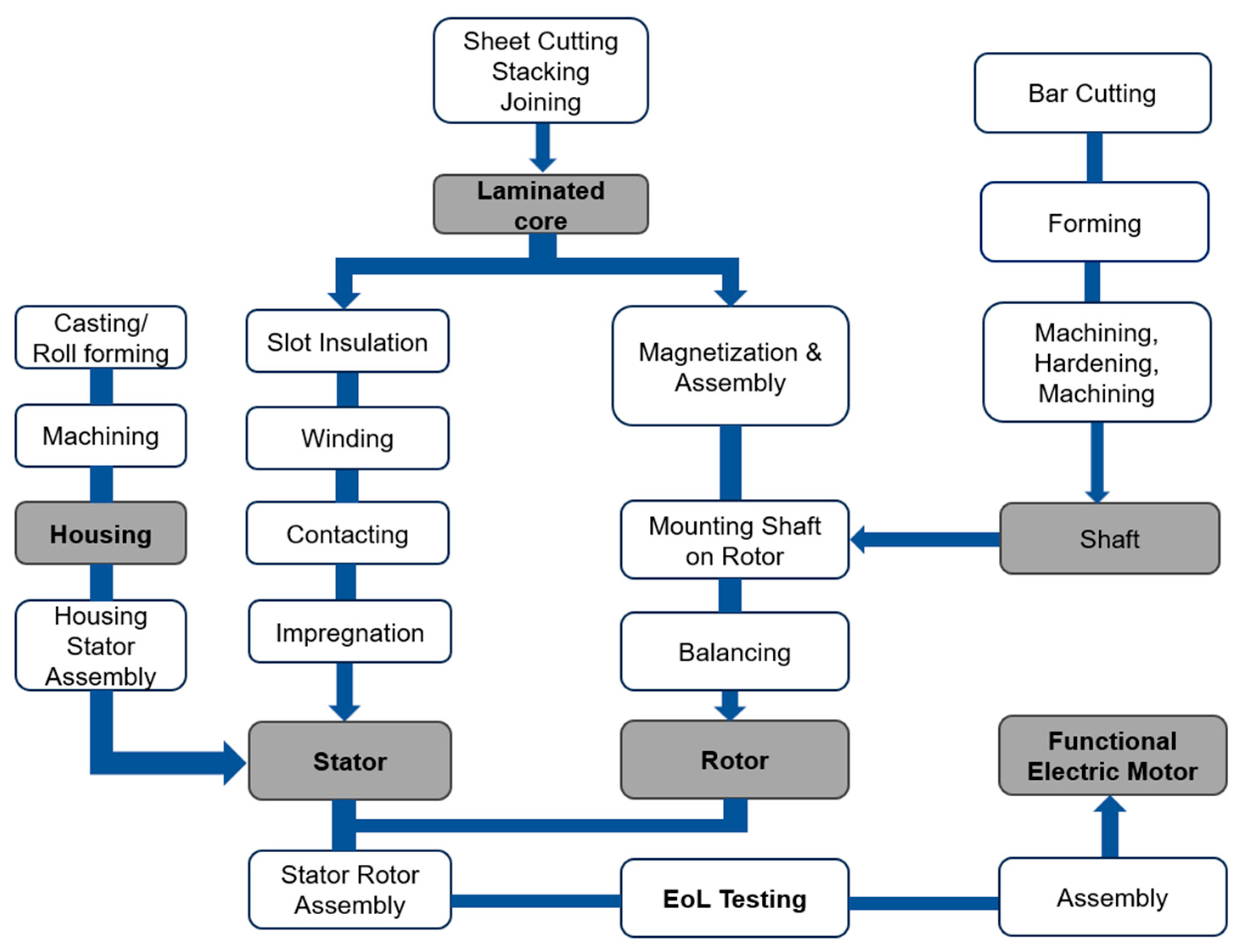
2. Manufacturing Process of an E-Motor

An overview of the manufacturing process of an e-motor is represented in Figure 2.
In Figure 2, the grey-colored boxes are the key components of the e-motor [11]. Each of the processes in the white-colored boxes contribute to manufacturing imperfections in several structural parameters including the air gap, inner and outer diameters of the stator, and position and volume of rotor magnets, as well as rotor eccentricity.

3. Necessity and Drawbacks of EOL Testing Methods

3.1. Necessity

The manufacturing tolerance of various electric motor parameters impacts not only the overall performance and quality of e-motors but also whether or not the machines can operate at all. In extreme cases, manufacturing variations can lead to faults that render these machines unsuitable for commercial deployment. EOL tests can identify such faults and inform subsequent action.
EOL tests comprise a cluster of quality control activities that take place after assembly, with different OEMs presumably conducting different tests, although specific data are not available. EOL tests at present can be primarily categorized into passive, active, and static assessments [11]:
  • Active tests involve operating the e-motors in various modes, encompassing both monitored and unmonitored conditions, including parameters like current, voltage, torque, and winding temperature.
  • Passive tests entail connecting the electric motor to an external motor and operating it as a generator. The same parameters as those in active tests can be examined during passive tests.
  • Static tests involve disconnecting the motor from the power supply or an external motor to evaluate its static characteristics.
The results of these tests are often pass or fail. This actionable label determines whether the machine will continue to commercial deployment or be discarded. The key EOL tests and the processes contributing to the faults detected in these tests are illustrated in Table 1.
These tests determine whether the manufacturing processes have been executed satisfactorily. The manufacturing imperfections in an e-motor can only be diagnosed at the end of the assembly line after the completion of the production steps [11].

3.2. Drawbacks

EOL testing and the correction of identified faults are notably time-intensive tasks. In most cases, the defective product is discarded, resulting in the wastage of materials, energy, and human work hours. Overall, significantly expensive EOL testing equipment and other resources are repeatedly needed to identify, not even repair, the e-motor. All these disadvantages of conventional end-of-line (EOL) testing approaches highlight the critical need for enhanced production processes that enable early fault detection and minimize overall EOL testing costs. A key priority is to pinpoint the critical parameters where investing in improved measurement accuracy, despite higher costs, can yield savings by preventing excessive EOL testing expenditures. By strategically allocating resources to control the most influential parameters through precision manufacturing and in-process monitoring, manufacturers can considerably reduce the burden on EOL testing while maintaining product quality and reliability.

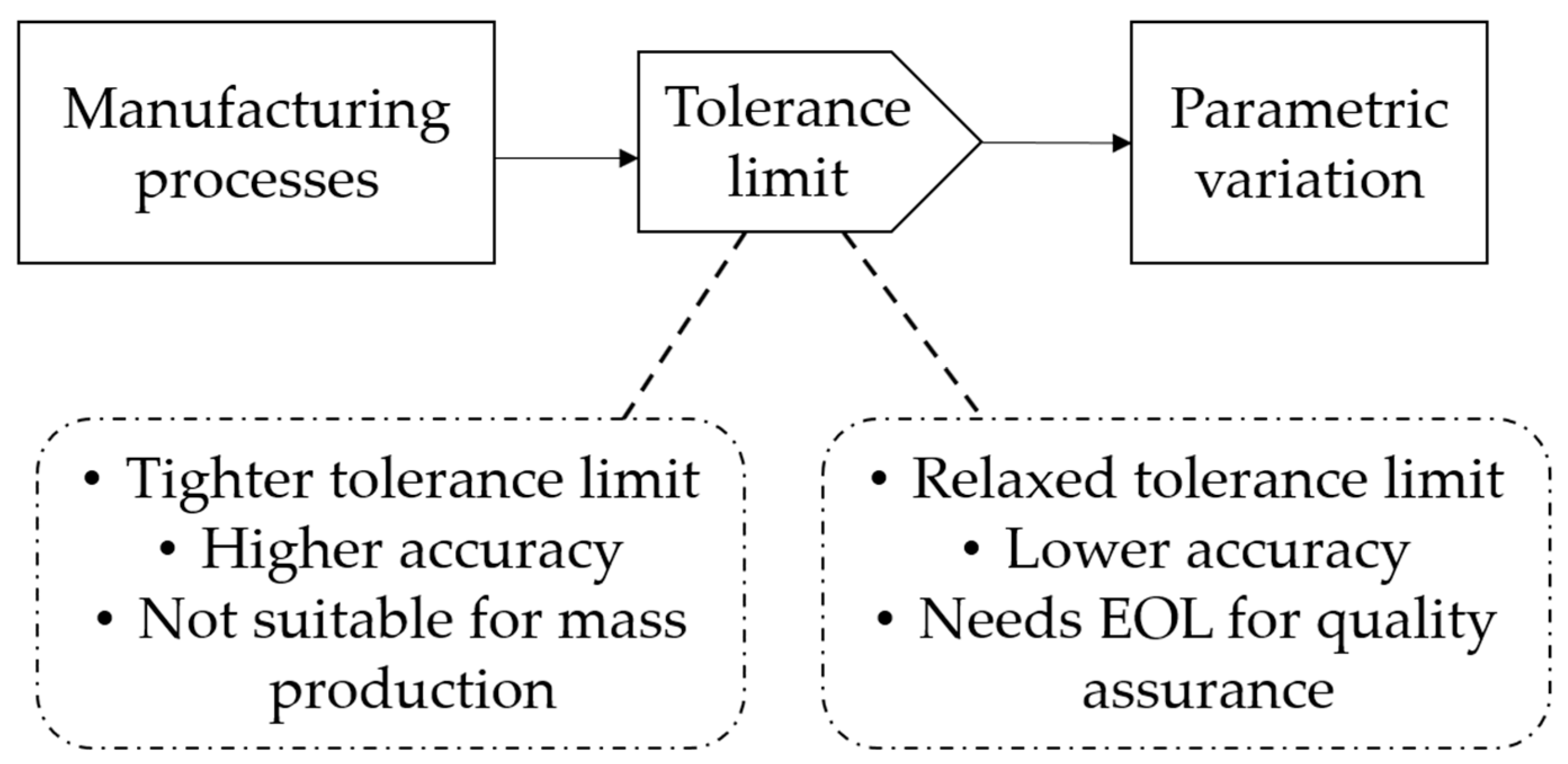
4. Tolerances of Key E-Motor Parameters

The successful operation and performance of e-motors rely on a variety of e-motor parameters, including both electrical and geometric characteristics. The tolerance of some parameters, which are addressed in this manuscript as “key parameters” or “critical parameters”, affects the performance of an e-machine more than the others do. The tolerance limits of these parameters can be set depending on the application of the e-machine. For example, for a Formula E electric racing car, which produces a lot of torque, the manufacturer might not need to focus on a parameter whose tolerance reduces the torque a little. On the other hand, for a premium sedan like Lucid Air or Tesla Model Y, the manufacturer should focus on imposing a tight tolerance on the parameter which affects cogging torque the most, as higher cogging torque translates to higher noise and vibration [13]. This section provides an overview of the key e-motor geometric parameters relevant to the testing and operation of e-motors.

4.1. Air Gap

From the studies conducted in [19,20,21,22], the air gap is the most crucial geometric parameter in e-motors, representing the physical separation between the rotor and the stator. It influences the magnetic flux linkage and the overall electromagnetic performance of the e-motor. The torque developed Te by a three-phase e-motor is defined by [23]
T e = 3 P 4 λ p m i q + L d L q i d i q
Here, P is the number of poles, λ p m is the permanent magnet flux linkage, and id and iq are the direct and quadrature axes’ currents, respectively. Inductances (Ld, Lq) are determined from the dimensions of the device, the length of the air gap, and the number of turns as
L = T 2 p h
where is the reluctance and Tph is the number of turns. The relationship between the reluctances in the direct axis and quadrature axis is established as follows [23]:
d q = l g + l m l g
Here, lg is the air gap, lm is the thickness of the magnet, and d and q are the reluctances of the direct axis flux path and quadrature flux path, respectively.
For an e-motor where the air gap is uneven due to the rotor’s design, changes in the air gap by as little as 0.1 mm can affect the e-motor’s shaft torque and torque ripple by as much as 1.12% and 56.27%, respectively [24]. A larger air-gap tolerance may lead to reduced power density, lower torque output, and increased magnetic reluctance. Conversely, a smaller air-gap tolerance may increase the risk of mechanical interference, vibration, and magnetic saturation. The sensitivity of the air gap increases as the speed rises, as this parameter affects the flux weakening capabilities [25].

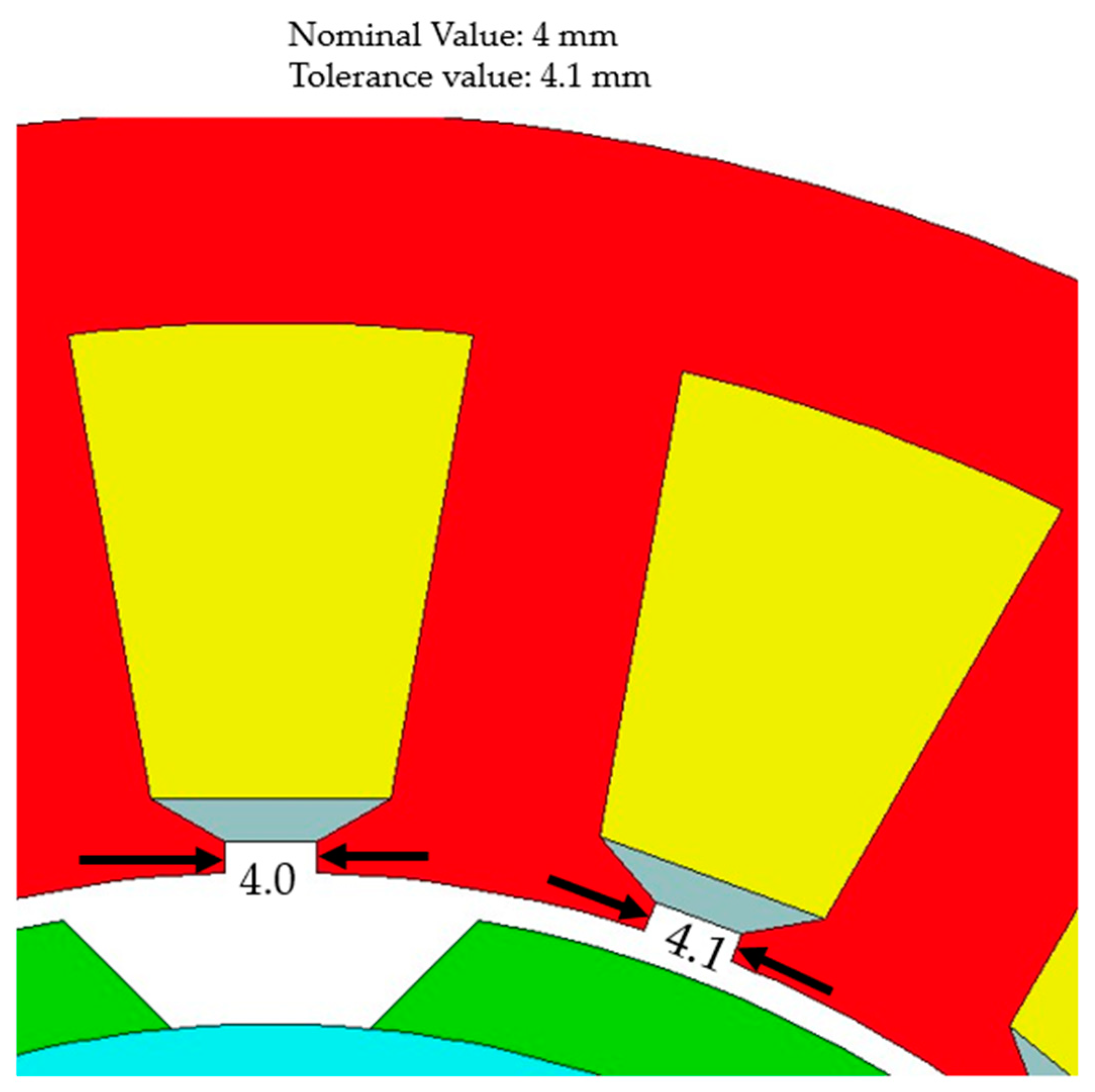
4.2. Stator Inner Diameter

The stator inner diameter is another important geometric parameter that directly affects the electrical and mechanical characteristics of an e-motor. It determines the slot dimensions and stator winding volume, which play a significant role in the motor’s cogging torque, torque ripple, and thermal management [26,27,28,29]. Deviations in the stator inner diameter from its nominal value directly translate into variations in the air gap length between the stator and rotor as well [30,31]. Tolerances in the stator inner diameter impact the back EMF as well [26,27]. Larger tolerances may introduce variations in electrical parameters, such as back EMF and inductance, affecting the e-motor’s performance. Excessive deviations in the stator inner diameter can also potentially lead to rotor–stator interference, increased friction losses, and mechanical stresses, compromising the e-motor’s integrity and lifespan [32]. Tighter tolerances help ensure consistent electrical characteristics and reduce manufacturing variations.

4.3. Rotor Magnet Parameters

The parameters associated with the rotor magnets, such as magnet thickness, magnet width, magnet placement, and magnetization strength, are critical factors that influence the overall magnetic field and torque production in e-motors [33,34,35,36]. The flux produced by the rotor magnet is directly proportional to its volume. Tolerances in rotor magnet thickness can cause the e-motor to have additional cogging torque harmonic components [36]. The study conducted in [37] shows that among five e-motors, the highest rated torque was produced by the e-motor with an interior W ¯ -shape PM rotor, with the largest magnet volume and largest magnet surface. Conversely, the e-motor with the smallest magnet surface to generate active magnetic flux produced the lowest torque. Moreover, variations in magnet dimensions from tolerances affect the mechanical integrity and strength of the rotor structure, limiting the maximum safe operating speed [38].

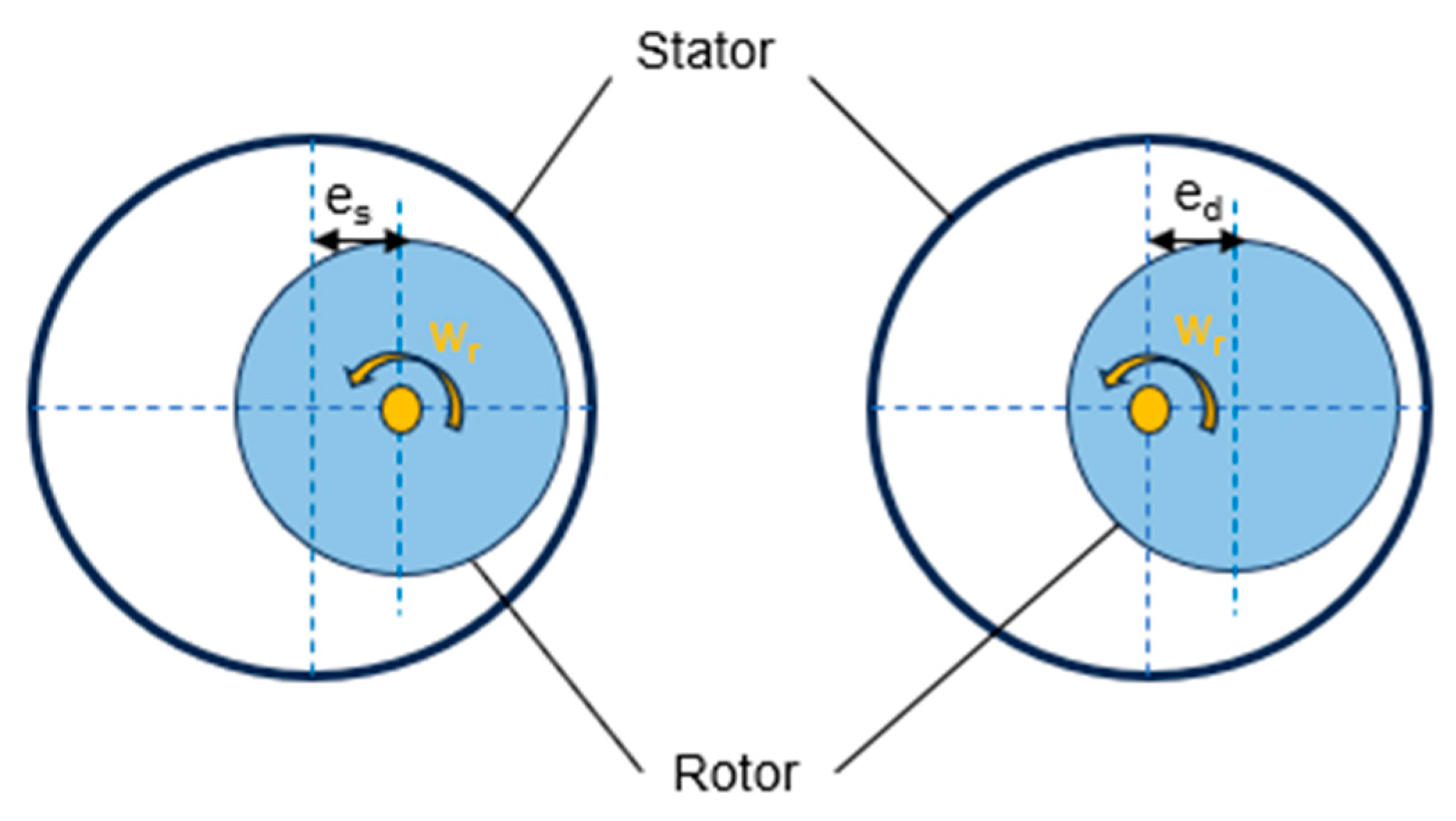
4.4. Rotor Eccentricity

Rotor eccentricity is a prevalent issue in PMSM, primarily resulting from errors during manufacturing or installation and wear in the bearings. Rotor eccentricity can also arise due to manufacturing imperfections such as distorted or oval-shaped stator cores, bent or misaligned rotor shafts, bearing misalignments or defects, and an uneven air gap length around the circumference [15]. Depending on the alignment of the stator axis, rotor axis, and rotating axis, rotor eccentricity can be categorized into two forms: static eccentricity (SE) and Dynamic Eccentricity (DE). SE happens when the rotor axis aligns with the rotating axis but deviates from the stator axis. DE happens when the stator axis aligns with the rotating axis but deviates from the rotor axis. Figure 3 illustrates the schematic representation of SE and DE. Es and ed represent the length of eccentricity for SE and DE, respectively [39].
Eccentricity in the rotor alters the radial electromagnetic force on the inner surface of the stator, leading to significant changes in vibroacoustic performance. This is because electromagnetic vibration and noise (e-NV) are highly influenced by the spatial characteristics of the force [39,40]. Rotor eccentricity can also cause several negative effects on the other output features of an electric motor. This includes introducing variations in air gap flux density, potentially leading to rotor–stator rubbing and mechanical failures, especially when the eccentricity levels are high [15,41].

4.5. Sensitivity Analysis to Identify Critical Parameters

4.5.1. Methodology

The authors of this manuscript conducted a comprehensive sensitivity analysis of all the structural parameters of an IPMSM to identify the most critical structural parameters of the e-motor. The study was conducted on an 8-pole, 48-slot IPMSM and the FEA method was used to calculate the electro-magnetic performance of the e-motor for varying geometric parameters. All the structural parameters subject to manufacturing tolerance were varied one parameter at a time to study the impact of each parameter’s tolerance. The e-motor had a single layer of V-shaped magnets. The parametric sweep was performed within the tolerance limits of each parameter. The inner and outer diameters of the stator were adjusted to be within a 0.5% deviation from the original design. The slot opening and air gap underwent variations within a range of 20%. The impact of changes in rotor parameters was investigated with adjustments limited to 10% of their initial dimensions. The step sizes were 10% of the deviation range. The influence of the parametric deviation was evaluated based on output torque, back EMF, torque ripple, and cogging torque. Data from each run of sensitivity analysis were compiled together and the deviation values were converted to percentages to understand the impact of the tolerance range on the change in output characteristics of the e-motor in terms of back EMF, torque ripple, output torque, and cogging torque.

4.5.2. Results

Table 2 shows the summary of the sensitivity analysis with six critical parameters identified from the parametric study. It was found that the air gap is the most critical parameter with the most significant influence on the output characteristics of the motor. It was also found that the shaft diameter, within the tolerance limit, has no influence on the output characteristics at all.

5. Solutions to Mitigate the Drawbacks of EOL Testing

5.1. In-Process Monitoring during Manufacturing Processes

Monitoring the manufacturing processes of e-motors has the potential to systematically identify and trace the source of emerging faults or anomalies. This approach facilitates the maintenance of a consistent quality of the components and enables the optimization of the manufacturing process [42]. In [43], the authors developed a quality inspection process for e-motor parts using image processing methods that can be applied at the lamination (stamping) step for fault detection. In-process monitoring can also be implemented at the contacting and magnet assembly stages. The authors in [44] showcased ML’s potential in e-motor production through two specific applications. For contact technologies like thermo and ultrasonic crimping, ML algorithms are applied for predictive maintenance, quality management, and process control. In the context of selective magnet assembly, a proposed ML-based concept forecasts cogging torque by examining magnet properties and process parameters.

5.2. Designing Tolerance-Insensitive E-Motor Components

The tolerance-insensitive design of permanent magnet motors aims to minimize the impact of manufacturing variations on motor performance, particularly cogging torque. Hybrid response surface methods combining analytical models and finite element analysis can optimize the design while accounting for manufacturing tolerances. Monte Carlo simulations validate the robustness of the optimized tolerance-insensitive design [4]. In [45], a tolerance-insensitive design process for the shape of the rotor magnet is proposed. The study focuses on the design process of surface-mounted PM motors and investigated the tolerance sensitivity of cycloid and eccentric curves in motor applications. A parameter, δq (an indicator that dictates the shape of a rotor), was introduced to compare their performance under identical conditions. Tolerance effects were assessed using the tolerance insensitivity rate (TIR), and the robustness of the curves was analyzed at different δq values.
The study included applying these curves to reference and tolerance models. Experimental verification was conducted by fabricating and testing motors, with finite element analysis (FEA) confirming that the results aligned with rotor tolerances. The study concluded that, particularly at higher δq values, the cycloid curve demonstrated greater robustness to tolerances compared to the eccentric curve, as observed in the reduced cogging torque, a crucial factor for improving noise and vibration harshness (NVH) characteristics in the electric power steering (EPS) system.
Figure 4 visualizes a typical case of manufacturing tolerance. This research investigates motor traits using the curtate epitrochoid (CET) and prolate epitrochoid (PET). A CET is formed when the fixed-point tracing trajectories on the rolling circle are positioned within the rolling circle. Conversely, PET curves are generated when the fixed point is situated outside the rolling circle. With this approach, the cogging torque of the prototype was reduced to 72% [45]. Future research work can be pursued to develop tolerance-insensitive components for interior PM motors. By employing tolerance sensitivity studies, robust design optimization, magnet shaping techniques, and systematic tolerance analysis, tolerance-insensitive components can be developed that maintain their performance despite manufacturing variations [4,45,46].

5.3. Prioritizing the Monitoring of Critical Parameters

Nearly all the structural parameters of an e-motor are subject to manufacturing tolerances. However, not all parameters equally affect the output characteristics of the e-motor. A few parameters, such as stator inner and outer diameters, magnet thickness, slot opening, and air gap (as supported by the sensitivity analysis results discussed in Section 4.5), contribute to the e-motor’s performance more than the others do. The authors of this manuscript suggest that the critical parameters of a particular e-motor model can be identified. During the production process, precedence can be given to monitoring the accuracy of these parameters to narrow down the quality control steps. This approach can optimize component-level quality assurance.

5.4. Automated Inspection Techniques

Industry 4.0 (I4.0) brings forth a range of technologies with significant potential to optimize the production process of electric motors. With advances in artificial intelligence (AI), machine learning (ML), and other data-driven approaches of Industry 4.0, we foresee the development of automated inspection systems capable of instantly spotting geometric inconsistencies [47,48]. As proposed in [47,49,50], sensors like camera and beam parameters and machine learning techniques like K-means clustering, decision tree, convolutional neural networks (CNNs), and conventional image processing can be implemented to inspect the components during manufacturing before their entry onto the assembly line. Once components’ quality is ensured, the required EOL testing efforts and associated costs will be reduced. As a result, the efficiency of the manufacturing process is enhanced, leading to a reduced cost of production.

5.5. Materials and Fabrication

To reduce the impact of manufacturing tolerances on e-motor components, several strategies can be employed related to materials selection and fabrication processes. Selecting permanent magnets with tight tolerances on remanence and intrinsic coercivity to control deviations in magnetization and magnetic field strength is suggested [26,51]. Additionally, the adoption of new materials and advanced manufacturing methods, such as 3D printing, could result in e-motors that are naturally more uniform and precise. In other words, using these innovative materials and techniques may contribute to the creation of e-motors with improved consistency and accuracy in their performance. The costs associated with 3D printing and conventional manufacturing processes can be compared, and the best production process can be validated.

5.6. Holistic Design

Future research efforts could involve a comprehensive design approach for e-motors. In this approach, the design process would consider a wide range of possible geometric irregularities or inconsistencies, considering the full spectrum of potential variations. The comprehensive tolerance analysis approach may involve modeling the assembly and capturing tolerance relationships between components, performing statistical tolerance analysis to understand how individual part tolerances stack up and propagate through the assembly, allocating optimal tolerances to components based on their sensitivity to performance metrics like torque ripple, vibrations, losses, etc., and incorporating tolerance synthesis methods like Taguchi’s robust design to minimize sensitivity to variations [46]. As demonstrated in [52], using numerical simulations coupled with multi-objective optimization can help identify optimal designs and manufacturing processes that balance performance, quality, and cost requirements while accounting for tolerance impacts holistically. Essentially, a more thorough and inclusive design strategy can be developed that anticipates and addresses various geometric factors for enhanced performance and reliability in electric motor systems.

6. Conclusions

It is one of the main requirements that the performance of EVs is consistent, as designed and as advertised. One way to ensure consistency is maintaining a high level of precision and tighter manufacturing tolerance while manufacturing the components of e-motors. However, with the current manufacturing processes, manufacturing tolerance is inevitable in the case of mass production. This brings us to EOL testing for quality assurance, which is also a substantially expensive step in manufacturing e-motors. The precision and dependability of EOL testing outcomes are largely impacted by the tolerances associated with various e-motor parameters, including stator inner and outer diameters, rotor positions, and air gap. Procedures such as sheet cutting, welding, stacking, stamping, thermal shrinking, and contacting executed to manufactured laminated stator cores and rotor cores introduce these tolerances in e-motors. This review paper discusses the crucial role of manufacturing tolerances of structural e-motor parameters on the e-motor’s performance and the significance of EOL testing for quality assurance. It explores the effects of tolerance limits on various e-motor parameters, such as torque, efficiency, back EMF, and e-NV. The paper also identifies key challenges and research gaps in this domain, offering recommendations for future research to address the limitations of EOL testing. The suitability of different approaches, namely, in-process monitoring, tolerance-insensitive design, prioritizing critical parameters, automated inspection techniques, updated fabrication process, and holistic designs, are discussed to mitigate the drawbacks of EOL testing. The overarching goal is to provide a comprehensive understanding of how manufacturing tolerances in structural e-motor parameters influence the EOL testing of electric motors and to provide guidance for future research on developing a broadscale, cost-effective manufacturing process.

Funding

This research work has been funded by Magna International, Inc. (Award No. ALLRP-555564-20), Canada Research Chairs Program (Award No. CRC-2019-00319) and NSERC.

Conflicts of Interest

Author Animesh Anik and K. Lakshmi Varaha Iyer were employed by the Magna International Inc. Author Rajeev Verma was employed by the Magna Services of America, Inc. The remaining authors declare that the research was conducted in the absence of any commercial or financial relationships that could be construed as a potential conflict of interest.

References

  1. Flach, A.; Draeger, F.; Ayeb, M.; Brabetz, L. A New Approach to Diagnostics for Permanent-Magnet Motors in Automotive Powertrain Systems. In Proceedings of the 8th IEEE Symposium on Diagnostics for Electrical Machines, Power Electronics & Drives, Bologna, Italy, 5–8 September 2011; pp. 234–239. [Google Scholar] [CrossRef]
  2. Liu, H.; Fan, W.; Zuo, Q.; Jiang, Y. Optimization Design of Three-Phase Permanent Magnet Synchronous Motor Drive System for Electric Vehicle. In Proceedings of the 2021 IEEE Sustainable Power and Energy Conference (iSPEC), Nanjing, China, 23–25 December 2021; pp. 3417–3422. [Google Scholar] [CrossRef]
  3. Ben Halima, N.; Ben Hadj, N.; Krichen, M.; Neji, R. Permanent Magnet Synchronous Motor Performance Study Dedicated to Parallel Hybrid Electric Vehicle. In Proceedings of the 2022 IEEE 21st International Conference on Sciences and Techniques of Automatic Control and Computer Engineering (STA), Sousse, Tunisia, 19–21 December 2022; pp. 629–634. [Google Scholar] [CrossRef]
  4. Jun, C.-S.; Kwon, B.-I.; Kwon, O. Tolerance Sensitivity Analysis and Robust Optimal Design Method of a Surface-Mounted Permanent Magnet Motor by Using a Hybrid Response Surface Method Considering Manufacturing Tolerances. Energies 2018, 11, 1159. [Google Scholar] [CrossRef]
  5. Mülder, C.; Franck, M.; Schröder, M.; Balluff, M.; Wanke, A.; Hameyer, K. Impact Study of Isolated and Correlated Manufacturing Tolerances of a Permanent Magnet Synchronous Machine for Traction Drives. In Proceedings of the 2019 IEEE International Electric Machines & Drives Conference (IEMDC), San Diego, CA, USA, 12–15 May 2019; pp. 982–987. [Google Scholar] [CrossRef]
  6. Mierczak, L.; Klimczyk, P.; Hennies, D.; Denke, P.; Siebert, S. Influence of Manufacturing Processes on Magnetic Properties of Stator Cores. In Proceedings of the 2020 International Conference on Electrical Machines (ICEM), Gothenburg, Sweden, 23–26 August 2020; pp. 901–908. [Google Scholar] [CrossRef]
  7. Sundaria, R.; Lehikoinen, A.; Arkkio, A.; Belahcen, A. Effects of Manufacturing Processes on Core Losses of Electrical Machines. IEEE Trans. Energy Convers. 2021, 36, 197–206. [Google Scholar] [CrossRef]
  8. Simón-Sempere, V.; Burgos-Payán, M.; Cerquides-Bueno, J.-R. Influence of Manufacturing Tolerances on the Electromotive Force in Permanent-Magnet Motors. IEEE Trans. Magn. 2013, 49, 5522–5532. [Google Scholar] [CrossRef]
  9. Coupek, D.; Verl, A.; Aichele, J.; Colledani, M. Proactive Quality Control System for Defect Reduction in the Production of Electric Drives. In Proceedings of the 2013 3rd International Electric Drives Production Conference (EDPC), Nuremberg, Germany, 29–30 October 2013; pp. 1–6. [Google Scholar] [CrossRef]
  10. Butov, A.; Verl, A. Comparison of End of Line Tests for Serial Production of Electric Motors in Hybrid Truck Applications. In Proceedings of the 2014 4th International Electric Drives Production Conference (EDPC), Nuremberg, Germany, 30 September–1 October 2014; pp. 1–4. [Google Scholar] [CrossRef]
  11. Tiwari, D.; Farnsworth, M.; Zhang, Z.; Jewell, G.W.; Tiwari, A. In-Process Monitoring in Electrical Machine Manufacturing: A Review of State of the Art and Future Directions. Proc. Inst. Mech. Eng. Part B J. Eng. Manuf. 2021, 235, 2035–2051. [Google Scholar] [CrossRef]
  12. Ge, X.; Zhu, Z.Q. Sensitivity of Manufacturing Tolerances on Cogging Torque in Interior Permanent Magnet Machines with Different Slot/Pole Number Combinations. IEEE Trans. Ind. Appl. 2017, 53, 3557–3567. [Google Scholar] [CrossRef]
  13. Islam, M.S.; Mir, S.; Sebastian, T. Issues in reducing the cogging torque of mass-produced permanent-magnet brushless DC motor. IEEE Trans. Ind. Appl. 2004, 40, 813–820. [Google Scholar] [CrossRef]
  14. Luu, T.-P.; Choi, S.-K.; Park, S.-Y.; Lee, J.-Y. Effect of Manufacturing Tolerances on Cogging Torque of Spoke-type Permanent Magnet Synchronous Motor. In Proceedings of the 2021 24th International Conference on Electrical Machines and Systems (ICEMS), Gyeongju, Republic of Korea, 10–13 October 2021; pp. 1054–1059. [Google Scholar] [CrossRef]
  15. Taran, N.; Rallabandi, V.; Ionel, D.M.; Zhou, P.; Thiele, M.; Heins, G. A Systematic Study on the Effects of Dimensional and Materials Tolerances on Permanent Magnet Synchronous Machines Based on the IEEE Std 1812. IEEE Trans. Ind. Appl. 2019, 55, 1360–1371. [Google Scholar] [CrossRef]
  16. Madariaga, C.; Jara, W.; Riquelme, D.; Bramerdorfer, G.; Tapia, J.A.; Riedemann, J. Impact of Tolerances on the Cogging Torque of Tooth-Coil-Winding PMSMs with Modular Stator Core by Means of Efficient Superposition Technique. Electronics 2020, 9, 1594. [Google Scholar] [CrossRef]
  17. Sachs, C.; Herrmann, F.; Butov, A.; Verl, A. Economic Evaluation of a Modular Production System for Electric Traction Motors. In Proceedings of the 2015 5th International Electric Drives Production Conference (EDPC), Nuremberg, Germany, 15–16 September 2015; pp. 1–6. [Google Scholar] [CrossRef]
  18. Chandekar, A.; Ugale, R.T. Interior Permanent Magnet Synchronous Traction Motor for Electric Vehicle (EV) Application Over Wide Speed Range. In Proceedings of the 2022 IEEE International Conference on Power Electronics, Drives and Energy Systems (PEDES), Jaipur, India, 14–17 December 2022; pp. 1–6. [Google Scholar] [CrossRef]
  19. Breban, S.; Dranca, M.; Chirca, M.; Pacuraru, A.-M.; Teodosescu, P.-D.; Oprea, C.-A. Experimental Tests on a Spoke-Type Permanent Magnets Synchronous Machine for Light Electric Vehicle Application. Appl. Sci. 2022, 12, 3019. [Google Scholar] [CrossRef]
  20. Seo, U.-J.; Chun, Y.-D.; Choi, J.-H.; Han, P.-W.; Koo, D.-H.; Lee, J. A Technique of Torque Ripple Reduction in Interior Permanent Magnet Synchronous Motor. IEEE Trans. Magn. 2011, 47, 3240–3243. [Google Scholar] [CrossRef]
  21. Modarres, M.; Vahedi, A.; Ghazanchaei, M. Effect of Air Gap Variation on Characteristics of an Axial Flux Hysteresis Motor. In Proceedings of the 2010 1st Power Electronic & Drive Systems & Technologies Conference (PEDSTC), Tehran, Iran, 17–18 February 2010; pp. 323–328. [Google Scholar] [CrossRef]
  22. Ghoneim, W.A.M.; Hebala, A.; Ashour, H.A. Sensitivity Analysis of Parameters Affecting the Performance of Radial Flux Low-Speed PMSG. In Proceedings of the 2018 XIII International Conference on Electrical Machines (ICEM), Alexandroupoli, Greece, 3–6 September 2018; pp. 968–974. [Google Scholar] [CrossRef]
  23. Chau, K.T. Electric Vehicle Machines and Drives: Design, Analysis and Application; Wiley-IEEE Press: Piscataway, NJ, USA, 2015; pp. 69–107. [Google Scholar] [CrossRef]
  24. Liang, J.; Parsapour, A.; Yang, Z.; Caicedo-Narvaez, C.; Moallem, M.; Fahimi, B. Optimization of Air-Gap Profile in Interior Permanent-Magnet Synchronous Motors for Torque Ripple Mitigation. IEEE Trans. Transp. Electrif. 2019, 5, 118–125. [Google Scholar] [CrossRef]
  25. Li, C.; Meng, T. A New Design Concept of PMSM for Flux Weakening Operation. In Proceedings of the 2016 19th International Conference on Electrical Machines and Systems (ICEMS), Chiba, Japan, 13–16 November 2016; pp. 1–5. [Google Scholar]
  26. Yu, J.-S.; Cho, H.-W.; Choi, J.-Y.; Jang, S.-M.; Lee, S.-H. Optimum Design of Stator and Rotor Shape for Cogging Torque Re-duction in Interior Permanent Magnet Synchronous Motors. J. Power Electron. 2013, 13, 546–551. [Google Scholar] [CrossRef]
  27. Jin, M.; Luo, L.; Chai, Y.; Song, J.; Jiang, F.; Shao, Y. Optimization Design of Permanent Magnet Synchronous Motor Torque Ripple Based on Stator Tooth Crown Slotting Method. In Proceedings of the 2023 IEEE 32nd International Symposium on Industrial Electronics (ISIE), Helsinki, Finland, 19–21 June 2023; pp. 1–6. [Google Scholar] [CrossRef]
  28. Kim, J.-M.; Yoon, M.-H.; Hong, J.-P.; Kim, S.-I. Analysis of Cogging Torque Caused by Manufacturing Tolerances of Surface-Mounted Permanent Magnet Synchronous Motor for Electric Power Steering. IET Electr. Power Appl. 2016, 10, 691–696. [Google Scholar] [CrossRef]
  29. Wrobel, R.; Mellor, P.H.; Holliday, D. Thermal Modeling of a Segmented Stator Winding Design. IEEE Trans. Ind. Appl. 2011, 47, 2023–2030. [Google Scholar] [CrossRef]
  30. Escobar, A.; Sánchez, G.; Jara, W.; Madariaga, C.; Tapia, J.A.; Riedemann, J.; Reyes, E. Impact of Manufacturing Tolerances on Axial Flux Permanent Magnet Machines with Ironless Rotor Core: A Statistical Approach. Machines 2023, 11, 535. [Google Scholar] [CrossRef]
  31. Villén, M.T.; Cañete, M.G.; Martín, E.; Comech, M.P.; Lozano, C. Manufacturing Tolerances Influence on Permanent Magnet Synchronous Generator (PMSG) Performance. 2016. Available online: https://windeurope.org/summit2016/conference/allfiles2/262_WindEurope2016presentation.pdf (accessed on 13 April 2024).
  32. Ma, Y.; Cao, J.; Li, L. Robust optimization design of permanent magnet synchronous motors for a solar airplane based on a lightweight structure. Energy Rep. 2023, 9, 1023–1031. [Google Scholar] [CrossRef]
  33. Ge, X.; Zhu, Z.Q. Influence of Manufacturing Tolerances on Cogging Torque in Interior Permanent Magnet Machines with Eccentric and Sinusoidal Rotor Contours. IEEE Trans. Ind. Appl. 2017, 53, 3568–3578. [Google Scholar] [CrossRef]
  34. Escobar, A.; Sánchez, G.; Jara, W.; Madariaga, C.; Tapia, J.; Degano, M.; Riedemann, J. Statistical Analysis of Manufacturing Tolerances Effect on Axial-Flux Permanent Magnet Machines Cogging Torque. In Proceedings of the 2021 IEEE Energy Conversion Congress and Exposition (ECCE), Vancouver, BC, Canada, 10–14 October 2021; pp. 4342–4346. [Google Scholar] [CrossRef]
  35. Zhao, Y.; Zhang, S.; Zhang, C.; Yang, G.; Yang, Y. Analysis of Cogging Torque of Permanent Magnet Motors under Mixed-Eccentricity and Manufacturing Tolerances. IEEE Access 2024, 12, 6672–6683. [Google Scholar] [CrossRef]
  36. Gasparin, L.; Cernigoj, A.; Markic, S.; Fiser, R. Additional Cogging Torque Components in Permanent-Magnet Motors Due to Manufacturing Imperfections. IEEE Trans. Magn. 2009, 45, 1210–1213. [Google Scholar] [CrossRef]
  37. Wang, A.; Jia, Y.; Soong, W.L. Comparison of Five Topologies for an Interior Permanent-Magnet Machine for a Hybrid Electric Vehicle. IEEE Trans. Magn. 2011, 47, 3606–3609. [Google Scholar] [CrossRef]
  38. Hou, P.; Ge, B.; Tao, D.; Pan, B.; Wang, Y. Rotor Strength Analysis of FeCo-Based Permanent Magnet High Speed Motor. Machines 2022, 10, 462. [Google Scholar] [CrossRef]
  39. Lin, F.; Zuo, S.; Deng, W. Impact of Rotor Eccentricity on Electromagnetic Vibration and Noise of Permanent Magnet Synchronous Motor. J. Vibroeng. 2018, 20, 923–935. [Google Scholar] [CrossRef]
  40. Emery, N.; Dasara, S.; Liang, J.; Al-Ani, D.; Emadi, A.; Bilgin, B. Study on the Effect of Dynamic Eccentricity on Acoustic Noise of an Interior Permanent Magnet Traction Motor. In Proceedings of the 2020 IEEE Transportation Electrification Conference & Expo (ITEC), Chicago, IL, USA, 23–26 June 2020; pp. 1147–1152. [Google Scholar] [CrossRef]
  41. Galfarsoro, U.; McCloskey, A.; Zarate, S.; Hernández, X.; Almandoz, G. Influence of manufacturing tolerances and eccentricities on the unbalanced magnetic pull in permanent magnet synchronous motors. In Proceedings of the 2020 International Conference on Electrical Machines (ICEM), Gothenburg, Sweden, 23–26 August 2020; pp. 1363–1369. [Google Scholar] [CrossRef]
  42. Bi, G.; Guo, Y.; Lin, J.; Han, W.; Zheng, M.; Chen, X. Principles of an In-Process Monitoring System for Precision Grinding Machine. In Proceedings of the 2011 Second International Conference on Mechanic Automation and Control Engineering, Hohhot, China, 15–17 July 2011; pp. 7546–7549. [Google Scholar] [CrossRef]
  43. Martínez, S.S.; Vázquez, C.O.; García, J.G.; Ortega, J.G. Quality Inspection of Machined Metal Parts Using an Image Fusion Technique. Measurement 2017, 111, 374–383. [Google Scholar] [CrossRef]
  44. Mayr, A.; Meyer, A.; Seefried, J.; Weigelt, M.; Lutz, B.; Sultani, D.; Hampl, M.; Franke, J. Potentials of Machine Learning in Electric Drives Production Using the Example of Contacting Processes and Selective Magnet Assembly. In Proceedings of the 2017 7th International Electric Drives Production Conference (EDPC), Würzburg, Germany, 5–6 December 2017; pp. 1–8. [Google Scholar] [CrossRef]
  45. Lee, C.-S.; Cha, K.-S.; Park, J.-C.; Lim, M.-S. Tolerance-Insensitive Design of the Magnet Shape for a Surface Permanent Magnet Synchronous Motor. Energies 2020, 13, 1311. [Google Scholar] [CrossRef]
  46. Narahari, Y.; Sudarsan, R.; Lyons, K.W.; Duffey, M.R.; Sriram, R.D. Design for tolerance of electro-mechanical assemblies: An integrated approach. IEEE Trans. Robot. Autom. 1999, 15, 1062–1079. [Google Scholar] [CrossRef]
  47. Mayr, A.; Weigelt, M.; von Lindenfels, J.; Seefried, J.; Ziegler, M.; Mahr, A.; Urban, N.; Kühl, A.; Hüttel, F.; Franke, J. Electric Motor Production 4.0—Application Potentials of Industry 4.0 Technologies in the Manufacturing of Electric Motors. In Proceedings of the 2018 8th International Electric Drives Production Conference (EDPC), Schweinfurt, Germany, 4–5 December 2018; pp. 1–13. [Google Scholar] [CrossRef]
  48. Mayr, A.; Weigelt, M.; Masuch, M.; Meiners, M.; Hüttel, F.; Franke, J. Application Scenarios of Artificial Intelligence in Electric Drives Production. Procedia Manuf. 2018, 24, 40–47. [Google Scholar] [CrossRef]
  49. Wang, F.; Zuo, B. Detection of surface cutting defect on magnet using Fourier image reconstruction. J. Cent. South Univ. 2016, 23, 1123–1131. [Google Scholar] [CrossRef]
  50. Tercan, H.; Khawli, T.A.; Eppelt, U.; Büscher, C.; Meisen, T.; Jeschke, S. Improving the Laser Cutting Process Design by Machine Learning Techniques. Prod. Eng. Res. Dev. 2017, 11, 195–203. [Google Scholar] [CrossRef]
  51. Bayley, D. Using manufacturing tolerances and practices to minimize unbalance [in electric motors]. In Proceedings of the Electrical Insulation Conference and Electrical Manufacturing and Coil Winding Conference, Rosemont, IL, USA, 22–25 September 1997; pp. 505–508. [Google Scholar] [CrossRef]
  52. Gotlih, J.; Brezocnik, M.; Pal, S.; Drstvensek, I.; Karner, T.; Brajlih, T. A Holistic Approach to Cooling System Selection and Injection Molding Process Optimization Based on Non-Dominated Sorting. Polymers 2022, 14, 4842. [Google Scholar] [CrossRef]
Figure 1. Causes and effects of manufacturing tolerance.
Energies 17 01913 g001
Figure 2. Manufacturing process of a PMSM.
Energies 17 01913 g002
Figure 3. Schematic plot of rotor eccentricity: SE (left), DE (right).
Energies 17 01913 g003
Figure 4. Fabrication tolerance for the width of slot opening.
Energies 17 01913 g004
Table 1. EOL tests and associated manufacturing processes.
Manufacturing
Process
Noise and
Vibration Test
Cogging Torque TestRunning Temperature TestDC
Hipot Test
Surge TestRotor
Eccentricity Test
Lamination
Insulation
Winding
Contacting
Impregnation
Bearing
Shaft
Assembly
Table 2. Summary of sensitivity analysis with identified critical parameters.
ParametersNominal Value (mm)Range of Deviation
(%)
Change in Back EMF (%)Change in Torque Ripple (%)Change in Shaft Torque (%)Change in Cogging Torque (%)
Stator outer diameter2000.505.211.850.002
Stator inner diameter142.60.424.6111.841.5130.505
Slot opening2.416.670.261.020.393.02
Air gap0.5518.180.0640.450.0319.65
Rotor magnet thickness5.86.90.581.651.41.04
Rotor magnet bar width14.73.42.811.582.910.63
Disclaimer/Publisher’s Note: The statements, opinions and data contained in all publications are solely those of the individual author(s) and contributor(s) and not of MDPI and/or the editor(s). MDPI and/or the editor(s) disclaim responsibility for any injury to people or property resulting from any ideas, methods, instructions or products referred to in the content.

