1. Introduction
In the modern world, switching from analog to digital television offers the user several advantages, such as high-definition (HD) video, six-channel surround audio (5.1), and data-broadcasting services. To make full use of the new audiovisual experience, the reception antenna must fulfill some requirements. Therefore, the design is very challenging for printed channel-bandwidth receiving antennas operating in the ultrahigh frequency band (UHF) [
1].
Another well-known and important aspect of this challenge is that wireless communications suffer from interference that affects performance in terms of network capacity. This interference may arise, for example, from frequencies assigned to mobile networks (GSM, 3G, LTE, etc.) amplified by the input low-noise amplifier following the antenna. The upper limit of the digital television (DTV) band is next to either the GSM or LTE band [
2]. Unlike other existing broadband antenna solutions, our novel proposed antenna avoids that interference because it has bandwidth close to a UHF IV and V band TV channel.
Printed antennas have several advantages, such as ease of manufacturing, reduced cost, and low volume. They are also thin in one dimension, making them suitable to operate in indoor enviroments and placed on the wall like a photograph or art frame. This makes such antennas a promising choice for DTV reception. However, a better solution in this application is to design an antenna with adjacent-channel rejection. Thus, the goal is to have the necessary bandwidth centered on the reception frequency while rejecting adjacent signals. In this framework, we designed an antenna that is intended for digital-terrestrial-television (DTT) reception.
The next section presents the state of the art. In
Section 3, the problem of bandwidth is addressed. In
Section 4, the antenna design is discussed, and its structure and dimensions are presented. In
Section 5, antenna performance is substantively discussed, making use of several simulation results and practical measurements. Lastly,
Section 6 concludes the paper.
2. Related Work
The Yagi–Uda antenna, commonly referred to as the Yagi antenna, is the most used antenna for TV reception. It was invented in 1926, so it is time to replace it with a novel design because of discoveries in new materials and structures since then. We need to move to a new type of antenna, but the research is tremendously challenging since the Yagi antenna’s performance is very good.
Few antenna designs for DTV applications are presented in the literature. The antenna presented in [
3] combines a planar inverted-F antenna (PIFA) and a loop antenna to achieve wideband operation in the UHF band. However, the operational bandwidth of the proposed PIFA–loop antenna is 460–870 MHz. Another interesting wideband antenna structure is a low-profile sinuous slot antenna constructed on a Rogers RO3206 substrate [
4], where the gain varied from 2.5 to 6 dBi in the frequency range of 0.53–4.86 MHz. As discussed above, these antennas require filtering due to the nearby frequencies/channels of the LTE band presented in this range, which can cause interference to the desired existing allocated services. Another limitation is that this PIFA–loop antenna is targeted to be used only indoors. In [
5], a monopole antenna is proposed for DTV applications with a wide operational bandwidth (451–912 MHz). Likewise, this design is not suitable for the main requirement, which is the reduction of interference from the LTE band. The monopole antenna [
5] has a gain of 1.7 dBi, which is very low compared to that of other DTV antennas. In order to increase the gain, a solution was proposed in [
6] that was based on a unidirectional array of bowtie antennas with an incision gap. The measured gain for this antenna array was 13.4–16.1 dBi. The design demonstrated good half-power beam width (HPBW) in the vertical plane of 15° from 470 to 862 MHz. Besides these features, the antenna also has return loss (RL) greater than 10 dB over a frequency range of 450–1014 MHz. A good example of a microstrip channel tuned antenna for Integrated Services Digital Broadcasting-Terrestrial (ISDB-T) was proposed in [
7], but the gain was very low, around −2.16 dBi.
Another challenging problem is how to reach the appropriate bandwidth of a microstrip antenna. For example, as was shown in [
8], a bandwidth increase of about 13% could be obtained by proximity coupling. However, this method has great complexity of design and construction. The simplest and most direct method is to increase the thickness of the substrate, that is, to use a thicker dielectric with a lower dielectric constant. This enables an increase in bandwidth and efficiency; however, the possibility of surface-wave formation may decrease antenna radiation performance [
9].
Extending this principle in order to achieve broader bandwidth, we propose a double-dielectric array antenna that adds another dielectric layer between patch substrate and ground plane. The second dielectric should have low permittivity, as discussed in
Section 3. Alternatively, low-permittivity composite materials and metamaterials with a magnetic response, could be used to improve the bandwidth of microstrip antennas [
10].
In this paper, we propose a new antenna that is well-matched at the frequency of interest and has the appropriate bandwidth, thus rejecting adjacent frequencies/channels such as the ones from the LTE band. The antenna was designed with linear polarization. Regarding the radiation pattern of the antenna, the main lobe had to be narrow enough to distinguish signals coming from different directions. Thus, by placing such antennas in a horizontal-array configuration, we could point the array radiation pattern maximum in the direction of the most favorable DTV broadcast signal (in terms of received power and modulation error rate), and simultaneously point the radiation pattern nulls in the direction of interfering signals. In this paper, we open a new path for motivating the research community to develop new antennas for TV reception. This paper takes a significant step towards that goal by proposing a new antenna for digital TV reception. Our design makes use of a microstrip patch antenna as a radiating element with applications at relatively low frequencies (in the DTV–UHF band). The advantage of the proposed design is that it can easily be integrated into printed circuit boards (PCBs). It is also versatile in adjusting the antenna resonant frequency by simply changing the patch length. However, antennas of this type have a relatively narrow bandwidth, which can result in performance/efficiency degradation. Nevertheless, such antennas are expected to have enough bandwidth to cover at least a single 8 MHz channel with a suitable resonant frequency (754 MHz, single-frequency network in Portugal).
3. Bandwidth of Double-Dielectric Patch Antenna
As discussed in
Section 2, in order to fulfill the bandwidth requirements, we chose air as the second dielectric in the double-dielectric substrate of the patch antenna. We aimed at obtaining antenna bandwidth of at least 8 MHz operating at the center frequency of 754 MHz.
The bandwidth of a patch antenna above a dielectric substrate depends on the dimensions of the patch and substrate permittivity. A number of approximate formulas for antenna bandwidth are available from the literature. Here, we based our bandwidth estimation on the approach developed in [
10].
Considering a resonant half-wavelength patch antenna with moderate patch width
satisfying
, where
is the free space wavelength, the relative antenna bandwidth can be estimated [
10] as
where
is the radiation quality factor of the antenna,
is the equivalent relative substrate permittivity, and
h is the substrate thickness. From this formula, increasing
h and decreasing
resulted in a larger bandwidth for an antenna with a given patch width.
As the air has a lower dielectric constant (
) compared to the average dielectric constant of the patch substrate (FR4), combining an air layer with a dielectric layer resulted in a reduction in the effective dielectric constant of the double-dielectric substrate (FR4 + air). Such a compound substrate is characterized by an equivalent relative permittivity
that can be estimated by the following formula:
where
is the relative permittivity of the FR4 substrate, and
r is a parameter determined by the thicknesses of the substrate and air layers
and
. In plate-capacitor approximation,
. A more accurate result could be obtained with the conformal mapping approach [
10], in which
where,
,
, with
,
, and
is the complete elliptic integral of the first kind [
11]. On the one side, when
,
and the equivalent permittivity approaches the permittivity of air. On the other side, when
,
and the equivalent permittivity approaches the permittivity of the substrate. In our case, as shown in
Section 4, air height
reached 3.2 mm.
4. Configuration of Proposed Double-Dielectric Antenna
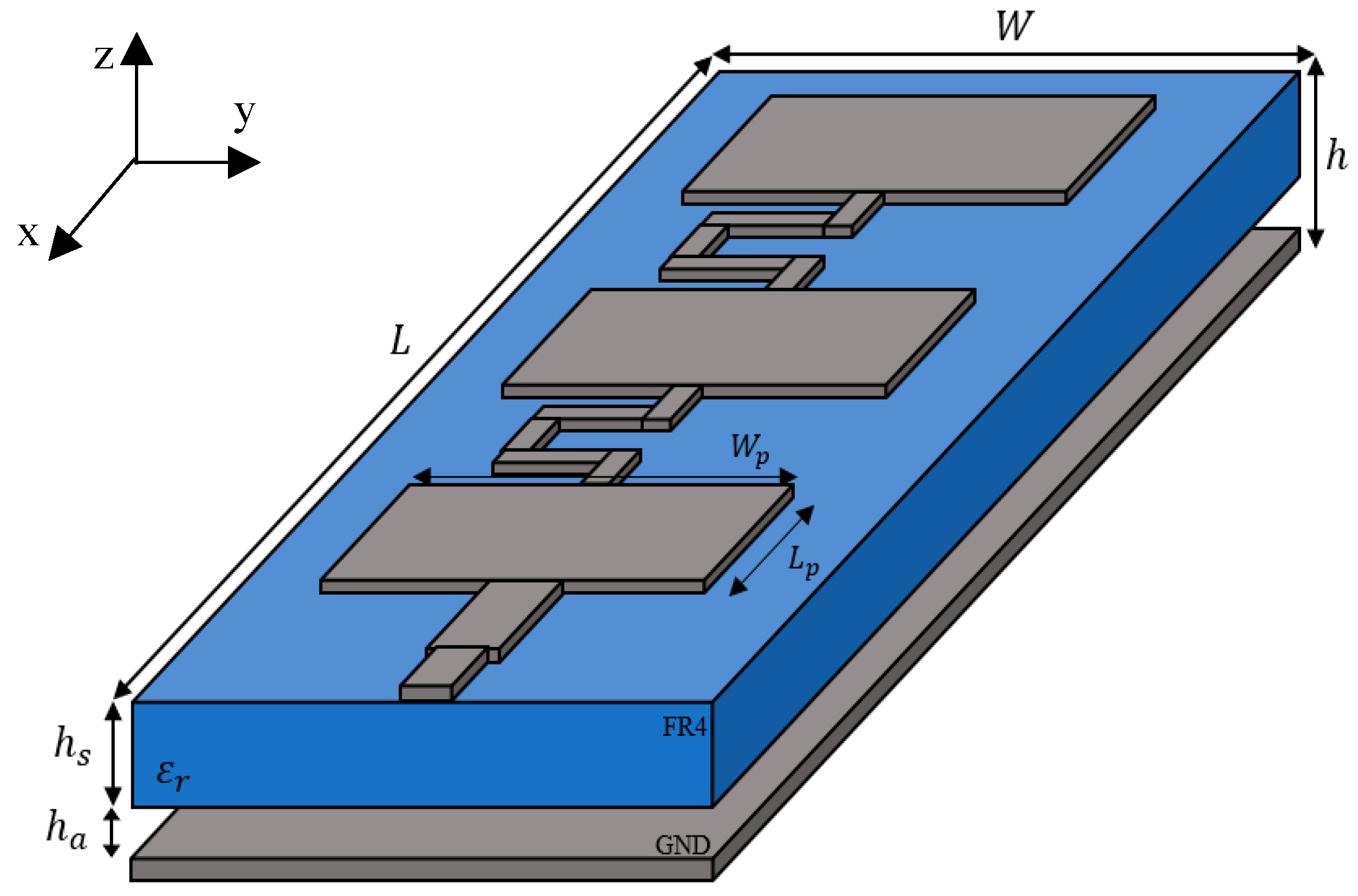
The geometry of the proposed microstrip antenna is shown in
Figure 1. It was expected to achieve 3 dB more gain by narrowing the beamwidth in the elevation direction as long as we doubled the number of patches. The antenna, consisting of three patches placed above a double-layer dielectric substrate, resulted in a good trade-off between size and gain. The three units increased the antenna gain by about 4.7 dB. It was fed by a microstrip transmission line through a 50 Ω SMA connector. Series-fed circuits were used to drive the three consecutive patches. The distance between the centers of the patches in the array equaled 199.0 mm (~
λ0/2 at the operation frequency). All patches were driven in phase because the radiation amplitude and phase at each patch were determined by the cumulative transmission characteristics of the preceding microstrip lines and patches. The connecting lines had the characteristic impedance of 100 Ω and no influence on the value of the central frequency [
12].
We followed a three-step approach. First, we theoretically designed the proposed antenna; second, we simulated the antenna behavior with the CST Microwave Studio electromagnetic simulator; third, we constructed and validated the antenna with some measurements.
On the basis of (1) and (2), we determined
and
. The upper dielectric was composed of FR4 with thickness
mm, relative permittivity
, and loss tangent tanδ = 0.015@1 GHz. The lower dielectric was composed of air with thickness
mm and relative permittivity equal to unity.
Section 3 outlines how the height of the antenna influenced bandwidth.
From the desired central frequency
= 754 MHz, we estimated each patch dimension
and
using the following equations [
13]:
where Δ
L is given by
and
h is the total height of the antenna, equal to
. All geometric parameters are listed in
Table 1.
Each of these three patches had a size of mm2. The overall size of the antenna was cm2.
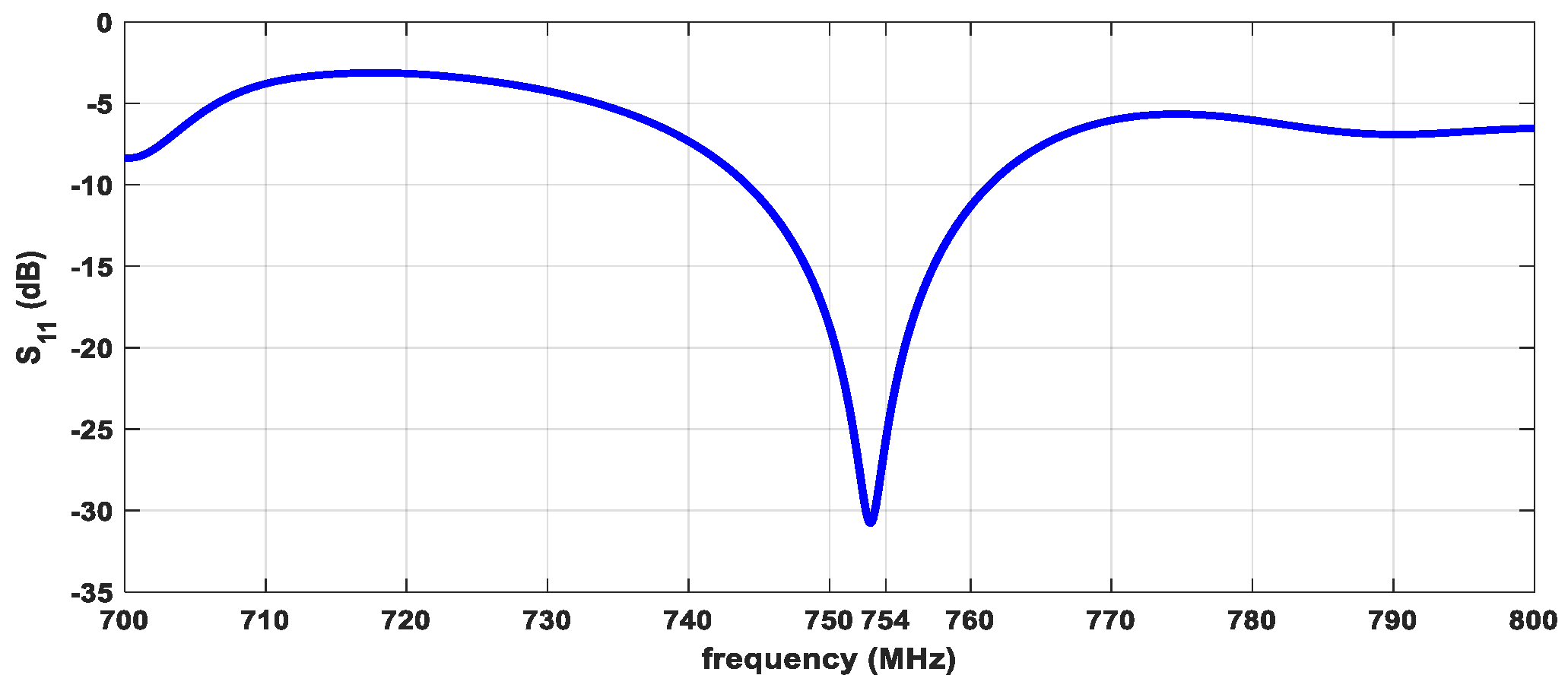
Figure 2 shows simulated reflection coefficient S
11 of the antenna. Assuming a return loss (RL) greater than 10 dB as the well-accepted criterion of good impedance matching, the proposed antenna was well-matched at the central frequency of 754 MHz and in channel 56 [750–758] MHz. The simulated bandwidth was 17 MHz, obtained at 10 dB return loss.
The line length connecting patches had high impedance, and its length was equal to 164.0 mm. In total, the electrical length of the line between each consecutive patch was equal to the wavelength divided by 2, λ/2. Therefore, the input impedance of the linear array is equivalent to the parallel connection of three patch antennas. A λ/4 transformer was then used to convert antenna input impedance into 50 Ω. The λ/4 transformer line had a length of 73 mm and a width of 24 mm. The 50 Ω microstrip line attached to the SMA connector had a width of 17.5 mm.
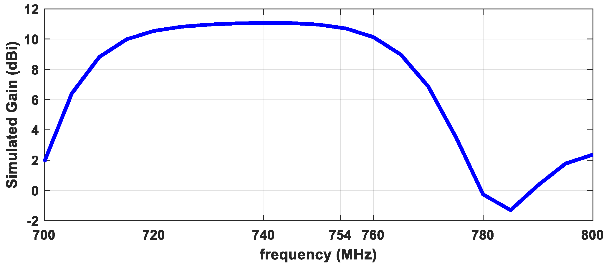
A gain value of 11.3 dBi was obtained in the direction of the maximal radiation, which was a reasonable value since the linear array was composed of the three single patches. The gain in function of frequency is shown in
Figure 3. The proposed antenna gain decreased above channel 56, as
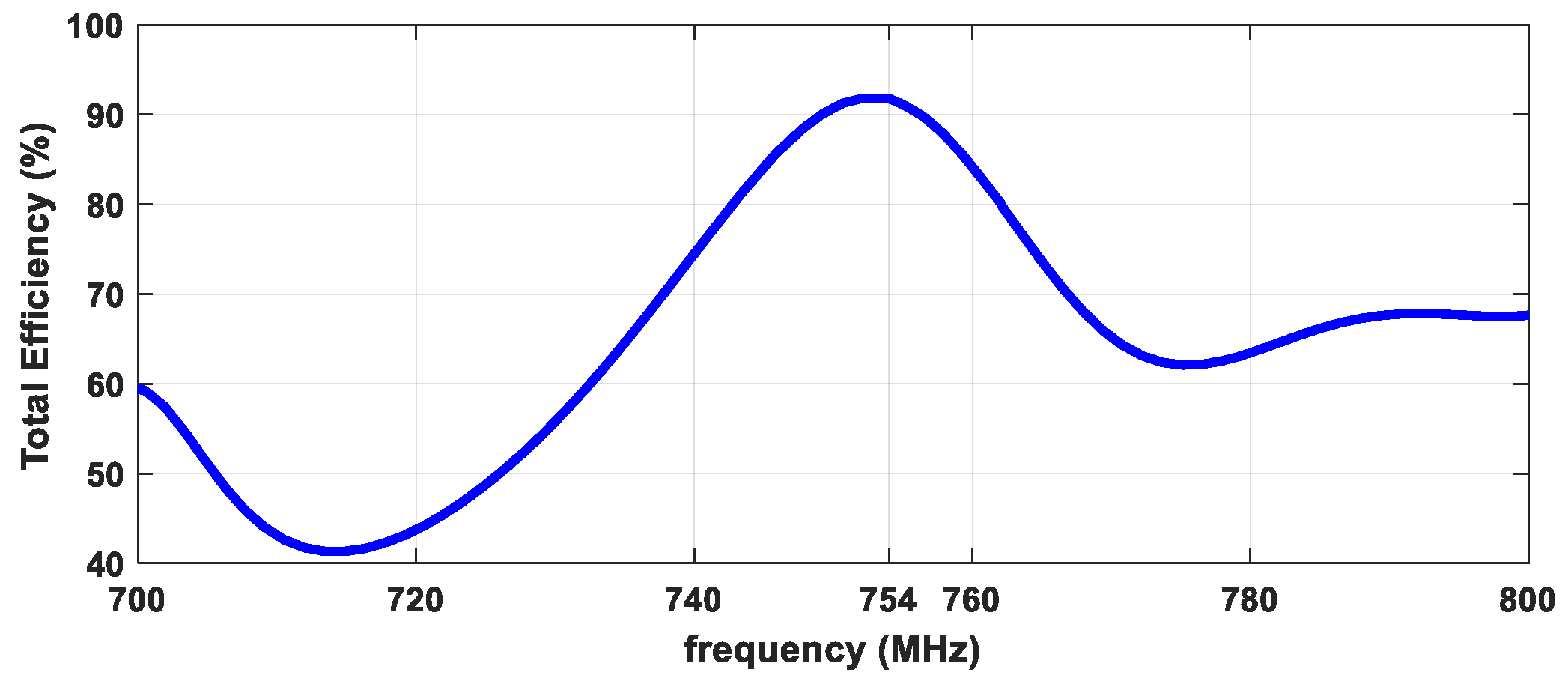
Figure 3 shows. Array efficiency was also simulated, achieving 92% at the central frequency, as shown in
Figure 4. The efficiency peak occurred at 754 MHz and decreased at adjacent channels.
5. Experimental Measurements
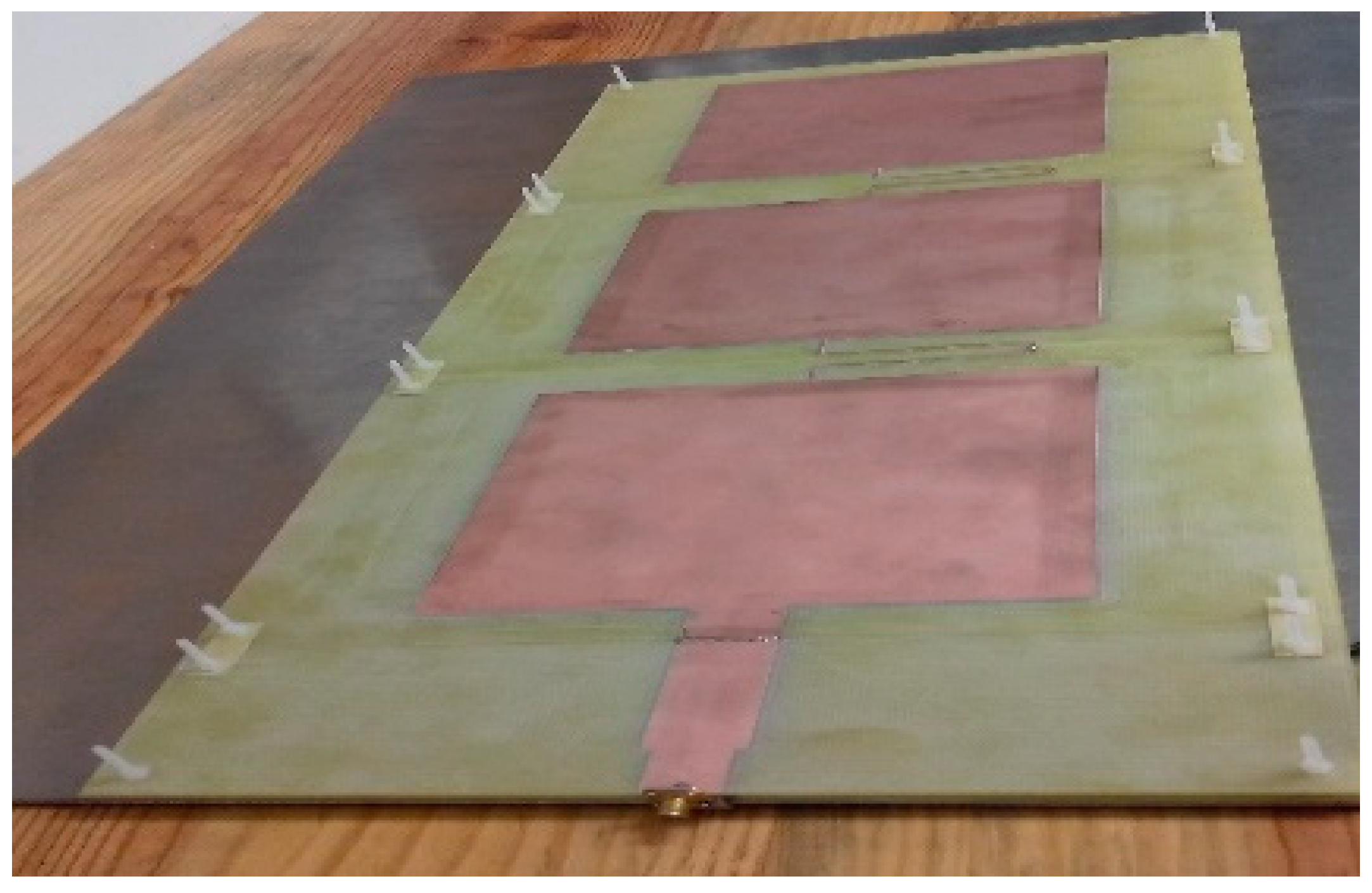
The last step consisted of constructing the proposed antenna in order to validate our design. Thus, we checked all obtained simulation results and found the real antenna performance. The proposed double-dielectric linear array of three patch elements is illustrated in
Figure 5. The bottom of
Figure 5 shows the input SMA connector. This female connector was soldered to a 50 Ω microstrip line. The other parts that are also visible in the figure are the λ/4 transformer, the three radiating patches, and the connecting lines between patches.
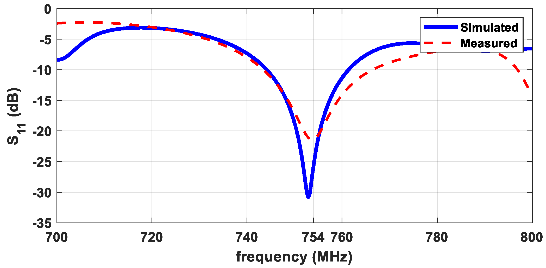
The base of substrate FR4 was raised with plastic M3 screws at a distance of 3.2 mm from the ground plane made of aluminum foil with 2.0 mm thickness. Experimental results of reflection coefficient S
11 were obtained by measuring with a vector network analyzer (VNA), as shown in
Figure 6. The center antenna frequency was clearly very close to 754 MHz, and at this frequency, S
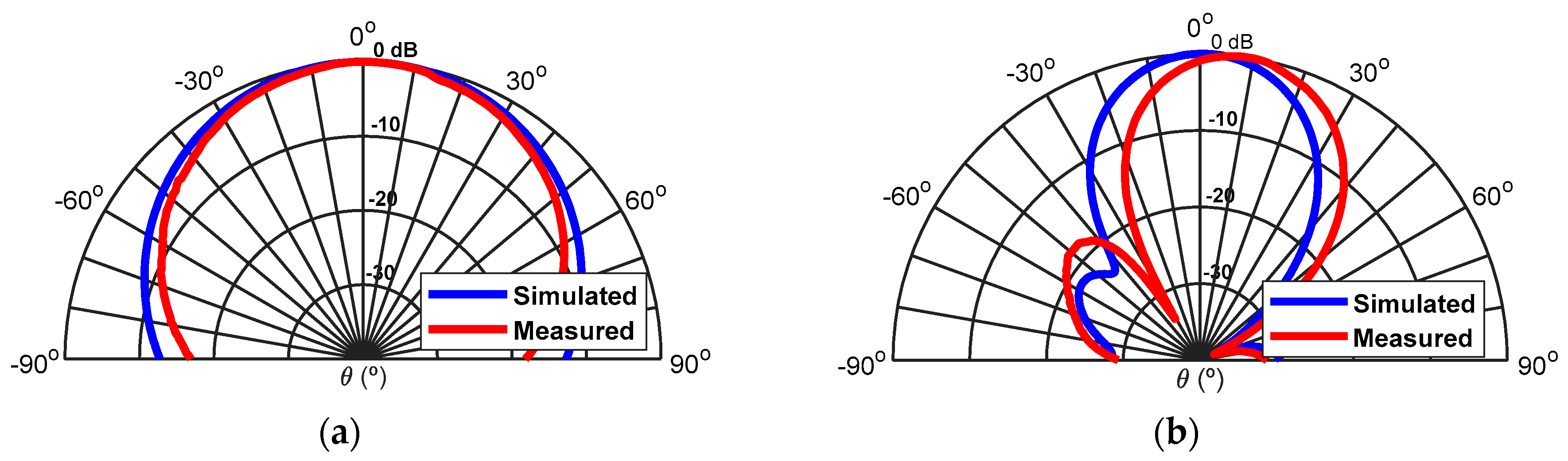
11 was less than −20 dB. We observed good agreement between the simulations and the measurements. However, from the practical measurements, we obtained a slightly greater bandwidth of about 25 MHz. The simulated and experimental radiation patterns obtained, in the anechoic chamber, of our proposed antenna are presented in
Figure 7. The experimental and simulation diagrams were very similar. Nevertheless, there was a small difference of 7° in the radiation diagrams in the vertical plane. This very small rotation in the radiation diagram was caused by a misalignment between the transmitting and receiving antennas.
The simulated and measured values of the gain were very similar, 11.3 and 10.5 dBi, respectively.
The vertical/elevation plane ( = 0°) had half-power bandwidth (HPBW) of 30° and the horizontal/azimuth plane ( = 90°) had a HPBW of 65°. These results proved that the proposed antenna had fan-beam radiation characteristics.
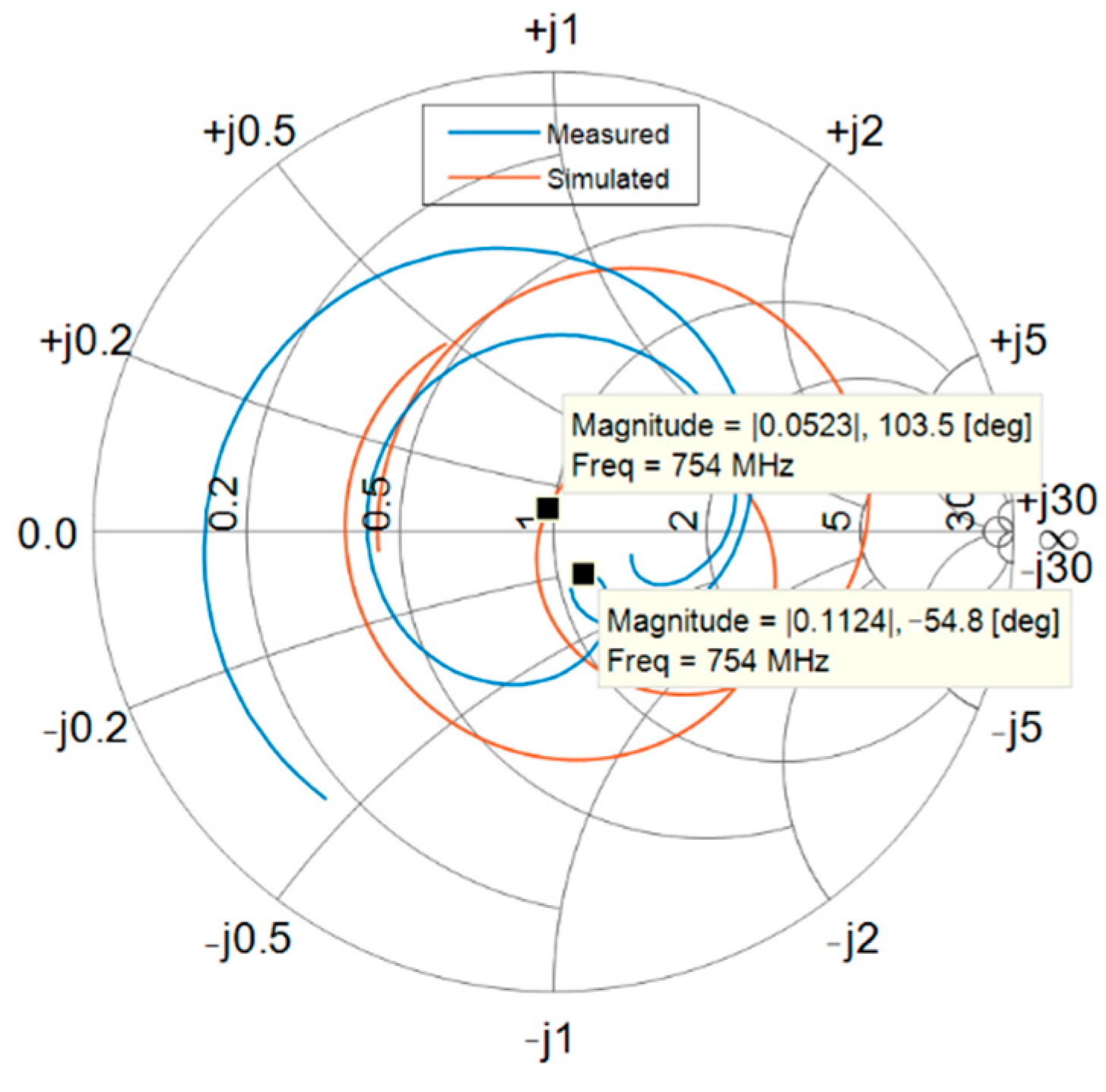
We also measured antenna input impedance through its input SMA connector, which was equal to Z
A = 55.9–j10.4 Ω at the central frequency, as shown in the Smith chart in
Figure 8. The Smith chart was drawn from 700 to 800 MHz. There was clear mismatching at frequencies away from the desired central frequency in the simulation and experimental curves.
6. Conclusions and Future Work
This paper presented and discussed a novel practical digital TV antenna that is suitable for indoor environments. The antenna can be placed on a wall, for example, since it is very thin—about 6.8 mm including the aluminum foil. The upper dielectric is composed of FR4 with thickness mm, relative permittivity , and tanδ = 0.015@1 GHz. The lower dielectric is composed of air, with thickness mm and relative permittivity equal to unity. The designed antenna has gain of 10.5 dBi, efficiency of 92%, and bandwidth of 25 MHz at the 10 dB return loss level. The proposed antenna overcomes the narrowband characteristics of common microstrip antennas, is mechanically robust, and can be connected to a coaxial cable without requiring any extra electronic components or devices such as baluns.
The proposed antenna has huge potential to be replicated and rearranged in an array. By adding electronic control to such an array, it is possible to perform smart beamforming in the azimuth plane, enabling new functionalities for DTV. An array of such antennas is quite useful for reducing self-interference caused by secondary transmitters in a single-frequency network (SFN) configuration. The antenna can also be spatially replicated to cover other applications in 5G broadcasting environments [
14]. Another advantage of our proposed antenna is its bandwidth of 25 MHz, avoiding interference in the frequency domain. Although the antenna dimensions may seem large (67.3 by 27.0 cm), the experimental demonstration presented here proved the main concept. Further reduction in the dimensions can be achieved by using reflectors or metamaterials with magnetic response, which is reserved for future work. This antenna can be used to receive any modern digital TV signals such as those specified in DVB-T/T2, ISDB-T, or ATSC standards.
Author Contributions
Antenna research and design, A.N., P.M., T.V., and J.M.; simulation, P.M. and T.V.; theoretical formulation, J.M. and S.M.; laboratory and field tests, A.N. and P.M.; methodology, A.N. and J.M.; writing, A.N., T.V., J.M., and S.M.; writing—review and editing, A.N. and J.M.; coordination, A.N. All authors have read and agreed to the published version of the manuscript.
Acknowledgments
This work is funded by FCT/MCTES through national funds and when applicable cofunded EU funds under the project UIDB/50008/2020-UIDP/50008/2020.
Conflicts of Interest
The authors declare no conflict of interest.
References
- Yeh, J.-T.; Liao, W.-J.; Chang, S.-H. Compact internal antenna for handheld devices with comprehensive DTV band coverage. IEEE Trans. Antennas Propag. 2014, 62, 3998–4007. [Google Scholar] [CrossRef]
- Polak, L.; Kaller, O.; Klozar, L.; Prokopec, J. Influence of mobile network interfering products on DVB-T/H broadcasting services. In Proceedings of the IFIP Wireless Days (WD), Dublin, Ireland, 21–23 November 2012. [Google Scholar]
- Van Trinh, T.; Kim, G.; Kim, J.; Jung, C.W. Wideband internal PIFA-loop antenna designed on the bezel of digital television applications for UHF band. IET Electron. Lett. 2018, 54, 1260–1262. [Google Scholar] [CrossRef]
- Gamec, J.; Repko, M.; Gamcová, M.; Gladišová, I.; Kurdel, P.; Nekrasov, A.; Fidge, C. Low profile sinuous Slot antenna for UWB sensor networks. Electronics 2018, 8, 127. [Google Scholar] [CrossRef] [Green Version]
- Huang, C.Y.; Jeng, B.M.; Yang, C.F. Wideband monopole antenna for DVB-T applications. IET Electron. Lett. 2008, 44, 1448–1450. [Google Scholar] [CrossRef]
- Luadang, B.; Phongcharoenpanich, C. Unidirectional bowtie array antenna with incision gap for digital video broadcasting-T2 base station. IET Microw. Antennas 2015, 9, 1087–1095. [Google Scholar] [CrossRef]
- Ballado, A.H.; Cruz, J.D.; Sejera, M.P.; Ingco, W.M.; Juan, C.M.; Nanao, D.N.; Navarro, J.A. Design of indoor microstrip TV antenna for integrated services digital broadcast—Terrestrial (ISDB-T) signal reception at 677 MHz. In Proceedings of the International Conference on Humanoid, Nanotechnology, Information Technology, Communication and Control, Environment and Management (HNICEM), Puerto Princesa Palawan, Philippines, 12–16 November 2014. [Google Scholar]
- Pozar, D.M.; Kaufman, B. Increasing the bandwidth of a microstrip antenna by proximity coupling. IET Electron. Lett. 1987, 23, 368–369. [Google Scholar] [CrossRef]
- Lau, N.U.; Sloan, R. Broadband millimeter-wave suspended microstrip antenna array. In Proceedings of the 2003 IEEE Antenna and Propagation Society International Symposium, Columbus, OH, USA, 22–27 June 2003. [Google Scholar]
- Ikonen, P.M.; Maslovski, S.I.; Simovski, C.R.; Tretyakov, S.A. On artificial magneto-dielectric loading for improving the impedance bandwidth properties of microstrip antennas. IEEE Trans. Antennas Propag. 2006, 54, 1654–1662. [Google Scholar] [CrossRef] [Green Version]
- Yoon, Y.J.; Kim, B. A New Formula for Effective Dielectric Constant in Multi-Dielectric Layer Microstrip Structure. In Proceedings of the IEEE 9th Topical Meeting on Electrical Performance of Electronic Packaging (Cat. No.00TH8524), Scottsdale, AZ, USA, 6 August 2000. [Google Scholar]
- Yuan, T.; Yuan, N.; Li, L.W. A novel series-fed taper antenna array design. IEEE Antennas Wirel. Propag. Lett. 2008, 58, 362–365. [Google Scholar] [CrossRef]
- Balanis, C.A. Antenna Theory, Analysis and Design: From Theory to Practice, 4th ed.; Wiley: Hoboken, NJ, USA, 2016. [Google Scholar]
- Miao, W.; Luo, C.; Zhao, Z. Lightweight 3-D Beamforming Design in 5G UAV Broadcasting Communications. IEEE Trans. Broadcast. 2020, 66, 515–524. [Google Scholar] [CrossRef]
| Publisher’s Note: MDPI stays neutral with regard to jurisdictional claims in published maps and institutional affiliations. |
© 2020 by the authors. Licensee MDPI, Basel, Switzerland. This article is an open access article distributed under the terms and conditions of the Creative Commons Attribution (CC BY) license (http://creativecommons.org/licenses/by/4.0/).


