
Wideband Circularly Polarized Filtering Hybrid Antenna

School of Electronics and Information, Hangzhou Dianzi University, Hangzhou 310018, China
*
Author to whom correspondence should be addressed.
Appl. Sci. 2022, 12(21), 11018; https://doi.org/10.3390/app122111018
Submission received: 29 September 2022
/
Revised: 24 October 2022
/
Accepted: 27 October 2022
/
Published: 31 October 2022
(This article belongs to the Special Issue Microwave Antennas: Theory, Material, Technology, Design and Application)
Abstract
:In this paper, a wideband circularly polarized (CP) filtering hybrid antenna is presented. The liquid dielectric resonator (DR) is excited by a microstrip-coupled cross-slot to generate CP radiation. Four inverted L-shaped strips are loaded on the ground plane to introduce an additional CP resonant point, then two adjacent axial ratio (AR) minima are combined to improve the bandwidth of the single-feed CP antenna. By etching a U-shaped slot and loading a C-shaped microstrip stub on the microstrip line, two tunable radiation nulls near the edges of the working band can be obtained without any extra filtering circuits. To verify the design, a filtering CP antenna is designed, fabricated, and tested. Measured results show that the antenna provides wider 3-dB AR and an impedance bandwidth of 38.8% from 1.36 to 2.02 GHz and 39.4% from 1.37 to 2.04 GHz, respectively. The realized gain of the proposed antenna is stable at about 7.8 dBi within the whole working band. A reasonable agreement between measured and simulated results is observed.
1. Introduction
Circularly polarized (CP) antennas are widely used in the wireless communication. Compared with the linearly polarized (LP) antennas, the circularly polarized (CP) antennas give transmitter and receiver more freedom in the orientation, and suppresses multipath interference [1]. A dielectric resonator antenna (DRA) has many striking features such as minute size, flexible excitation and various resonant modes [2]. Some techniques are used to generate the CP radiation for different DRAs, and these techniques are classified into the single and multi-feeding mechanisms [3]. Generally, the multi-fed techniques often need extra complex excitation networks, thus increasing the loss, while the single-fed design is more flexible, with relatively simple structure and low cost. However, the single-fed CP antennas usually have a narrower 3-dB AR bandwidth of only 6% or less.
Some techniques have been skillfully applied to extend the AR bandwidth of the single-fed CP DRAs. For example, some of the irregular-shaped DRAs were reported [4,5,6], such as T-shaped DR, stair-shape DR and trapezoidal DR. A triple-CP-mode stacked DRA with a 3-dB AR bandwidth of 27% is reported in [7]. However, the irregular-shaped DRAs are usually made of solid material, and it is difficult to theoretically analyze such irregularly structure. In [8], a rectangular DR excited by an Archimedean spiral slot owns an AR bandwidth of 25.5% with a gain of more than 5 dBi. In [9], a wide 3-dB AR bandwidth of 41.01% is obtained by using a stair-shaped coupling slot. In [10], a wideband CP magnetoelectric dipole antenna is proposed by using an extended hook shape.
As the front end of the communication system, the antenna is usually cascaded with filters through the matching circuit to suppress unwanted interference signals. The introduction of a matching circuit not only increases the size of the whole design, but also reduces the gain of the antenna. In order to realize miniaturization and low loss, some filtering antennas with both radiation and filtering characteristics are proposed [11]. Generally, there are mainly two methods to construct the filtering antennas. The first is to use the antenna as the last resonator of the filter, which increases the size and insertion loss of the antenna. The second design is to introduce small modifications into the radiator or the feeding structure [12,13,14], such as loading shorting pins, or parasitic strips on the microstrip line. Since no complex filtering circuits are involved, the performance of the antenna is not affected or less affected. In [14], a U-slot, a defected ground structure (DGS), and parasitic patches are introduced to generate radiation nulls. At the frequencies of radiation nulls, surface currents are concentrated on the parasitic structures. The antenna cannot be radiated effectively, thereby achieving a good filtering response.
In this paper, a novel wideband single-fed filtering CP hybrid antenna is proposed. The CP field of liquid DRA is excited by a cross-slot. Two radiation nulls are introduced by designing a U-shaped slot and a C-shaped stub on the microstrip line, respectively, by loading four inverted L-shaped metals around the DR to extend the AR bandwidth. The 3-dB AR bandwidth of the proposed structure almost completely overlaps with the 10-dB impedance bandwidth; the effective bandwidth is 38.2%.
2. Antenna Configuration and Design
Figure 1 shows the geometry of the proposed filtering CP antenna. It consists of a rectangular PVC container, four inverted L-shaped metals and a ground plane with a cross-feeding slot. Liquid ethyl acetate is contained in the container, and the properties of the liquid can be queried on the website [15]. Liquid ethyl acetate is a kind of organic solution with relatively stable radiation characteristics. The relative permittivity of ethyl acetate is about 6.6, and the loss tangent is about 0.02 in our working band. The transparent PVC container with size of 58 × 58 × 40 mm3 has the thickness of 2 mm. The ethyl acetate as a transparent DR is placed on the middle of the substrate. When the antenna is not working, the liquid can be drawn out, which improves the stealthiness and reduces the radar cross section (RCS) of the antenna. The size and thickness of the substrate are 150 × 150 mm2 and 0.813 mm, respectively. The detailed configuration of the feeding network is shown in Figure 1c. The stepped feedline is used to flexibly adjust impedance matching. A U-shaped slot is etched on the first part of the feedline, and a C-shaped stub is loaded on the second part of the feedline to realize a band-pass property.
3. Working Principle
CP field can be excited by a cross-slot with different lengths. As shown in Figure 2, the design process of the proposed antenna is demonstrated by comparing three reference antennas. Ant.1 is a cross-slot-fed liquid DRA, Ant.2 is with four rotationally symmetric inverted-L metals fed by a cross-slot, and Ant.3 is obtained by combining DRA and the inverted-L metals. The simulated AR results of the three antennas are compared in Figure 2d. As seen from the figure, the Ant.1 generates two AR minima at 1.46 GHz and 1.8 GHz, respectively. Furthermore, Ant.2 generates another CP minimum at 2 GHz due to the rotationally symmetric structure. The Ant.1 and Ant.2 were combined, and the two structures were skillfully adjusted to make the AR minima at adjacent frequency, thus the overall AR bandwidth can be extended. It is worth mentioning that the CP fields generated by the inverted L-shaped metals have the same sense of polarization with the fields generated by the cross-slot.
In order to investigate the CP characteristic of the proposed antenna, the electric field distribution on the y’oz and x’oz plane are shown in Figure 3, where the x’ and y’ are along the laying direction of the cross-slot. It can be confirmed that the is excited at 1.44 GHz, and meanwhile, the electric field distribution at 1.7 GHz is shown in Figure 3b at the x’oz plane corresponding to the mode of . The orthogonal and mode are resonated at a different frequency due to the cross-slot with unequal length. Thus, the CP at first AR minimum is achieved due to the and mode, while the second AR minimum is achieved due to the short slot with x’-polarization and mode.
Figure 4a,b gives the simulated AR with a different length of short slot and the inverted L-shaped strip, respectively. As seen in the Figure 4a, the short slot has serious effects on the second AR minimum, but a slight effect on the first AR minimum and no effect on the third AR minimum. This is because the length of the short slot has little influence on the mode, thus having a slight effect on the first AR minimum. The third AR minimum is introduced by the rotationally symmetric inverted L-metals, so the length of the short slot has no effect on the third AR minima. Figure 4b shows that when the length of the inverted L-shaped metal increases, the frequencies of the third AR minimum gradually decreases, while the other two AR minima are hardly affected.
To investigate the mechanism of the radiation null of the proposed filtering antenna, a parametric study is performed. As shown in Figure 5a, with increasing the length of the C-shaped strip, the lower radiation null is shifted to the lower frequency, while the upper radiation null remains unchanged. The influence of the U-shaped slot etched on the feedline is studied, as shown in the Figure 5b, with increasing the length of the strip, the upper radiation null is shifted to the lower frequency, while the lower null is not affected.
4. Antenna Performance
To validate the presented design concept, a prototype antenna is fabricated and measured. The photographs of the prototype and the measured environment are shown in Figure 6. Figure 7a shows the simulated and measured results of the proposed antenna. The impedance bandwidth with |S11| < −10 dB is 38.8% from 1.36 to 2.02 GHz, and the 3-dB AR bandwidth is 39.4% from 1.37 to 2.04 GHz as shown in Figure 7b. The usable overlap bandwidth of the antenna is 38.2% (1.37 GHz~2.02 GHz). Figure 8 exhibits the simulated and measured realized gains. When the U-slot and C-stub are not loaded, the gain of the antenna changes smoothly and has no obvious filtering response. The gain of the final antenna in the whole operating band is stable around 7.8 dBi, while two radiation nulls will be generated at the lower and upper edges of the working band, respectively. The smaller frequency offset is due to the tiny air bubbles in the liquid causing the actual size to be different from the simulated size.
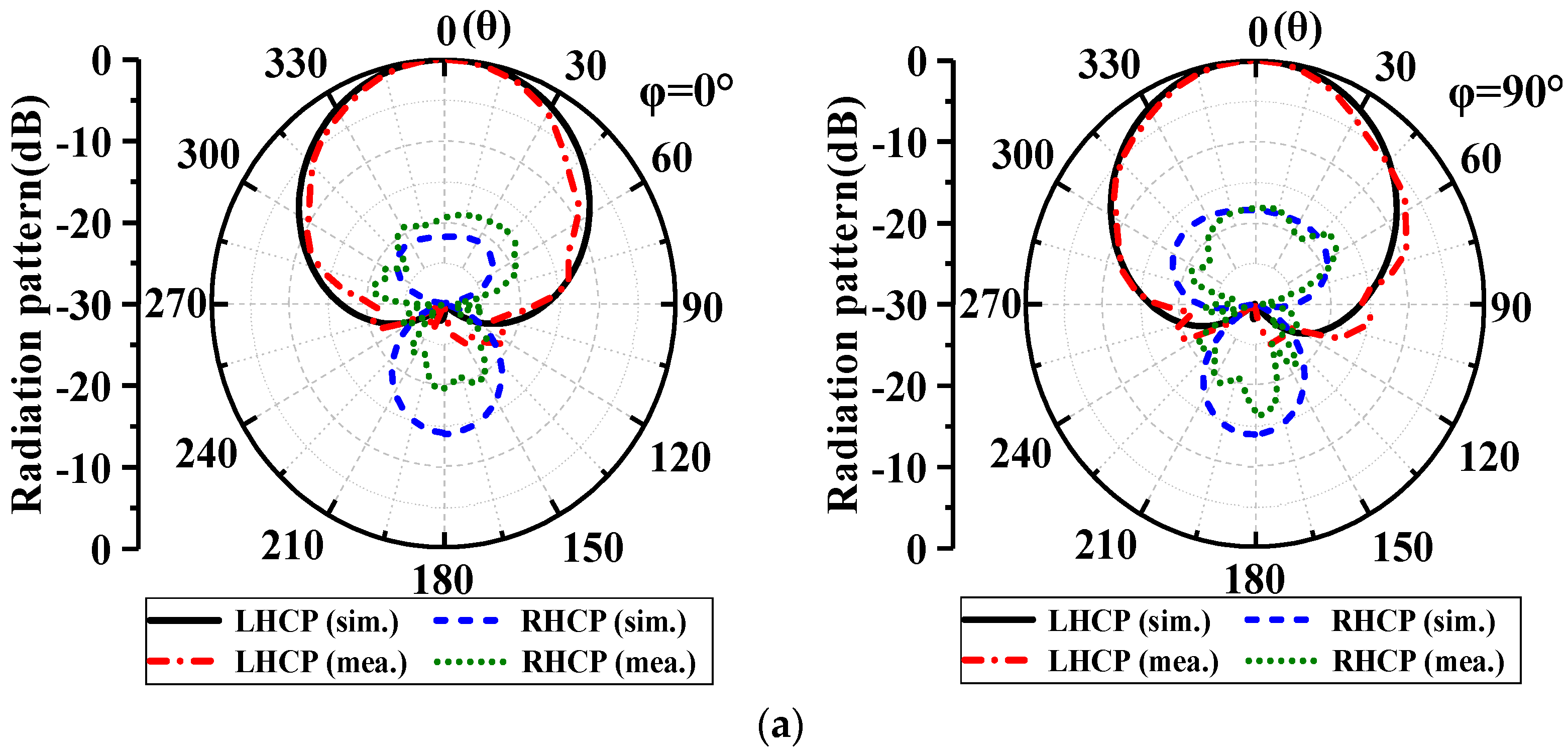
Figure 9a–c depicts the simulated and measured radiation patterns of the prototype in the xz and yz planes at 1.5, 1.74, and 2 GHz, respectively. The measured results agree well with the simulation results. It is observed that radiation patterns of the antenna remain stable throughout the frequency band.
The performance comparisons of the proposed antenna and other CP antennas are conducted, as shown in Table 1. Although the design in [16] owns a wider bandwidth, but the proposed antenna has a higher gain and owns the filtering properties. Compared with the CP antenna in [17,18,19,20], the proposed antenna has a wider bandwidth. Compared with the above design, the proposed work has advantage of wide bandwidth, high gain, and filtering property.
5. Conclusions
A single-fed wideband CP filtering liquid DRA has been designed based on an antenna fusion approach. The C-stub microstrip and U-slot is applied to obtain the radiation null at the lower and upper band, respectively. The inverted L-shaped strips are combined with the liquid DRA, and the extra AR minimum is introduced in interest band, thus expanding the working bandwidth. The antenna offers entirely overlapped AR and impedance bandwidths of 38.2% and the average gain within working band is 7.8 dBi. As a result, both the stable radiating and the filtering performance have been obtained without applying any specific extra circuit. The proposed wideband circularly polarized filtering hybrid antenna is promising for wireless communication systems.
Author Contributions
Conceptualization, Y.Q. and S.X.; data curation, Y.Q.; methodology, S.X.; software, S.X.; validation, Y.Q.; investigation, S.X.; resources, Y.Q.; writing—original draft preparation, Y.Q.; writing—review and editing, Y.Q.; visualization, S.X.; supervision, Y.Q.; project administration, Y.Q.; funding acquisition, S.X. All authors have read and agreed to the published version of the manuscript.
Funding
This research was supported by the National Natural Science Foundation of China (61901143), the Natural Science Foundation of Zhejiang Province (LQ19F010010).
Institutional Review Board Statement
Not applicable.
Informed Consent Statement
Not applicable.
Data Availability Statement
Not applicable.
Conflicts of Interest
The authors declare that they have no conflict of interest in the publication of this manuscript.
References
- Gao, S.; Luo, Q.; Zhu, F. Circularly Polarized Antennas; Wiley: West Sussex, UK, 2014. [Google Scholar]
- Luk, K.M.; Leung, K.W. Dielectric Resonator Antennas; Research Studies Press: Baldock, UK, 2003. [Google Scholar]
- Petosa, A. Dielectric Resonator Antenna Handbook; Artech House: Norwood, MA, USA, 2007. [Google Scholar]
- Lu, L.; Jiao, Y.-C.; Liang, W.; Zhang, H. A novel low-profile dual circularly polarized dielectric resonator antenna. IEEE Trans. Antennas Propag. 2016, 64, 4078–4083. [Google Scholar] [CrossRef]
- Sun, W.; Yang, W.; Chu, P.; Chen, J. Design of a wideband circularly polarized stacked dielectric resonator antenna. IEEE Trans. Antennas Propag. 2019, 67, 591–595. [Google Scholar] [CrossRef]
- Trinh-Van, S.; Yang, Y.; Lee, K.; Hwang, K.C. Single-Fed Circularly Polarized Dielectric Resonator Antenna with an Enhanced Axial Ratio Bandwidth and Enhanced Gain. IEEE Access 2020, 8, 41045–41052. [Google Scholar] [CrossRef]
- Yang, W.; Sun, W.; Tang, H.; Chen, J. Design of a circularly polarized dielectric resonator antenna with wide bandwidth and low axial Ratio values. IEEE Trans. Antennas Propag. 2019, 67, 1963–1968. [Google Scholar] [CrossRef]
- Zou, M.; Pan, J.; Nie, Z. A wideband circularly polarized rectangular dielectric resonator antenna excited by an archimedean spiral slot. IEEE Antennas Wirel. Propag. Lett. 2015, 14, 446–449. [Google Scholar] [CrossRef]
- Varshney, G.; Pamdey, V.S.; Kumar, L. Wideband circularly polarized dielectric resonator antenna with stair-shaped slot excitation. IEEE Trans. Antennas Propag. 2017, 65, 1380–1383. [Google Scholar] [CrossRef]
- Askari, H.; Hussain, N.; Sufian, M.A.; Lee, S.M.; Kim, N. A Wideband Circularly Polarized Magnetoelectric Dipole Antenna for 5G Millimeter-Wave Communications. Sensors 2022, 22, 2338. [Google Scholar] [CrossRef] [PubMed]
- Nadan, T.L.; Coupez, J.P.; Person, C. Integration of an antenna/filter device, using a multi-layer, multi-technology process. In Proceedings of the 1998 28th European Microwave Conference, Amsterdam, The Netherlands, 5–9 October 1998; pp. 672–677. [Google Scholar]
- Hu, P.F.; Pan, Y.M.; Leung, K.W.; Zhang, X.Y. Wide-/dual-band omnidirectional filtering dielectric resonator antennas. IEEE Trans. Antennas Propag. 2018, 66, 2622–2627. [Google Scholar] [CrossRef]
- Liu, Y.; Leung, K.W.; Ren, J.; Sun, Y. Linearly and circularly polarized filtering dielectric resonator antennas. IEEE Trans. Antennas Propag. 2019, 67, 3629–3640. [Google Scholar] [CrossRef]
- Yang, W.; Chen, S.; Xue, Q.; Che, W.; Shen, G.; Feng, W. Novel filtering method based on metasurface antenna and its application for wideband high-gain filtering antenna with low profile. IEEE Trans. Antennas Propag. 2019, 67, 1535–1544. [Google Scholar] [CrossRef]
- Liquid Antenna Resources. [Online]. Available online: www.liquidantennas.org (accessed on 30 March 2021).
- Yang, M.; Pan, Y.; Yang, W. A singly fed wideband circularly polarized dielectric resonator antenna. IEEE Antennas Wirel. Propag. Lett. 2018, 17, 1515–1518. [Google Scholar] [CrossRef]
- Xiang, B.J.; Zheng, S.Y.; Pan, Y.M.; Li, Y.X. Wideband circularly polarized dielectric resonator antenna with bandpass filtering and wide harmonics suppression response. IEEE Trans. Antennas Propag. 2017, 65, 2096–2101. [Google Scholar] [CrossRef]
- Wang, W.; Chen, C.; Wang, S.; Wu, W. Circularly polarized patch antenna with filtering performance using polarization isolation and dispersive delay line. IEEE Antennas Wirel. Propag. Lett. 2020, 19, 1457–1461. [Google Scholar] [CrossRef]
- Ji, S.; Dong, Y.; Pan, Y.; Zhu, Y.; Fan, Y. Planar circularly polarized antenna with bandpass filtering response based on dual-mode SIW cavity. IEEE Trans. Antennas Propag. 2021, 69, 3155–3164. [Google Scholar] [CrossRef]
- Yang, W.-J.; Pan, Y.-M.; Zhang, X.-Y. A single-layer low-profile circularly polarized filtering patch antenna. IEEE Antennas Wirel. Propag. Lett. 2021, 20, 602–606. [Google Scholar] [CrossRef]
Figure 1.
Geometry of the proposed wideband CP filtering antenna. (a) Perspective view. (b) Top view. (c) Configuration of the feeding network. a = 70, b = 30, ox = 10, oy = 60, W = 58, H = 40, L1 = 38, L2 = 76, G = 150, Lf1 = 29, Lf2 = 17, Lf3 = 45, La = 20, Ls = 52, Wa = 4, Wf2 = 5, Wf3 = 1.6, L3 = 23, L4 = 0.9 and all in millimeter.

Figure 2.
Configurations of the reference antennas. (a) Ant. 1. (b) Ant. 2. (c) Ant. 3. (d) ARs.

Figure 3.
Simulate the E-field of proposed antenna. (a) y’oz at 1.47 GHz. (b) x’oz at 1.7 GHz.

Figure 4.
Simulated ARs for different length of (a) the cross slot. (b) the inverted L-shaped metals.
Figure 4.
Simulated ARs for different length of (a) the cross slot. (b) the inverted L-shaped metals.

Figure 5.
Simulated realized gains for different length of (a) the C−stub. (b) the U−slot.

Figure 6.
The proposed antenna. (a) Fabricated prototype. (b) Measured environment.

Figure 7.
Simulated and measured results. (a) Reflection coefficient. (b) AR.

Figure 8.
Simulated and measured realized gain.

Figure 9.
Simulated and measured normalized radiation patterns. (a) 1.5 GHz. (b) 1.74 GHz. (c) 2 GHz.
Figure 9.
Simulated and measured normalized radiation patterns. (a) 1.5 GHz. (b) 1.74 GHz. (c) 2 GHz.


Table 1.
Comparison between the proposed antenna and previously published works.
| Ref. | Center Frequency (GHz) | AR Bandwidth | Impendence Bandwidth | Element | Gain (dBi) | Filtering | Size (λ03) |
|---|---|---|---|---|---|---|---|
| [13] | 2.44 | 4.1% | 4.5% | DRA | 5.1 | Yes | 0.8 × 0.8 × 0.15 |
| [16] | 2.97 | 49.5% | 46.9% | DRA | 4.73 | No | 0.72 × 0.72 × 0.18 |
| [17] | 1.835 | 35% | 27.8% | DRA | 6.5 | Yes | 0.68 × 0.68 × 0.138 |
| [18] | 2.435 | 3.8% | 3.8% | patch | 6.1 | Yes | 0.72 × 0.72 × 0.019 |
| [19] | 5.03 | 3.9% | 7.2% | patch | 8 | Yes | 1.01 × 1.01 × 0.036 |
| [20] | 2.44 | 4.5% | 5.3% | patch | 8.3 | Yes | 0.98 × 0.98 × 0.02 |
| This work | 1.695 | 39.4% | 38.8% | DRA | 7.8 | Yes | 0.85 × 0.85 × 0.22 |
Publisher’s Note: MDPI stays neutral with regard to jurisdictional claims in published maps and institutional affiliations. |
© 2022 by the authors. Licensee MDPI, Basel, Switzerland. This article is an open access article distributed under the terms and conditions of the Creative Commons Attribution (CC BY) license (https://creativecommons.org/licenses/by/4.0/).
Share and Cite
MDPI and ACS Style
Qian, Y.; Xie, S. Wideband Circularly Polarized Filtering Hybrid Antenna. Appl. Sci. 2022, 12, 11018. https://doi.org/10.3390/app122111018
AMA Style
Qian Y, Xie S. Wideband Circularly Polarized Filtering Hybrid Antenna. Applied Sciences. 2022; 12(21):11018. https://doi.org/10.3390/app122111018
Chicago/Turabian StyleQian, Yahui, and Shumin Xie. 2022. "Wideband Circularly Polarized Filtering Hybrid Antenna" Applied Sciences 12, no. 21: 11018. https://doi.org/10.3390/app122111018
Note that from the first issue of 2016, this journal uses article numbers instead of page numbers. See further details here.