Featured Application
This paper presents a simulation model based on cosimulation between ADAMS and MATLAB/Simulink, designed to evaluate pick-points for an arbitrary object gripped with a two-fingered (2-F) robotic gripper.
Abstract
Robotic bin-picking performance has been gaining attention in recent years with the development of increasingly advanced camera and machine vision systems, collaborative and industrial robots, and sophisticated robotic grippers. In the random bin-picking process, the wide variety of objects in terms of shape, weight, and surface require complex solutions for the objects to be reliably picked. The challenging part of robotic bin-picking is to determine object pick-points correctly. This paper presents a simulation model based on ADAMS/MATLAB cosimulation for robotic pick-point evaluation for a 2-F robotic gripper. It consists of a mechanical model constructed in ADAMS/View, MATLAB/Simulink force controller, several support functions, and the graphical user interface developed in MATLAB/App Designer. Its functionality can serve three different applications, such as: (1) determining the optimal pick-points of the object due to object complexity, (2) selecting the most appropriate robotic gripper, and (3) improving the existing configuration of the robotic gripper (finger width, depth, shape, stroke width, etc.). Additionally, based on this analysis, new variants of robotic grippers can be proposed. The simulation model has been verified on a selected object on a sample 2-F parallel robotic gripper, showing promising results, where up to 75% of pick-points were correctly determined in the initial testing phase.
1. Introduction
The term Industry 4.0 (I4.0) represents the fourth industrial revolution. Its beginning dates to 2010, and the term Industry 4.0 is often used interchangeably with the term “smart industry.” The concept’s core idea lies in that today’s industry needs answers to economic, sociological, and political changes generated by the end-users [1]. However, the industry usually requires some time to adapt to new concepts and adjusts its business accordingly. Therefore, the novelties in the industry need some time to be implemented, as is the case with I4.0. While there is no single definition of what precisely the term I4.0 represents, we can generally divide the I4.0 concept into three major categories, such as Cyber-Physical Systems (CPS), the Internet of Things (IoT), and cloud computing [2]. The first concept describes the ability to couple the physical properties of a system with advanced computational algorithms, such as in the field of predictive maintenance [3]. The IoT relates to the interconnection of various devices that rely on sensors, communication, networking, and information processing technologies [2]. Sensor networks can gather data regarding the manufacturing process and then later use that data to optimize the process. Cloud computing refers to sharing documents, collaboration, distributed production, and resource optimization [4]. The main advantage of cloud computing is scalability, which means extra computing power is ensured if additional demand arises [5]. We can conclude that the I4.0 concepts were developed to improve industrial processes by collecting and using the data for optimization.
Since the industry depends heavily on logistics services, the logistics processes must be adapted accordingly to cope with the increasing demands. Hence, the Logistics 4.0 (L4.0) term has been coined based on the Industry 4.0 term [6,7]. Logistics 4.0 describes advanced usage of various technological advancements such as those in Industry 4.0, such as intelligent devices, IoT, and other CPS, which aim to reorganize some of the basic concepts of logistics [7]. This holds especially true due to the rising trends of E-commerce [8] and the concerning trends of workforce deficiency and the aging population [9]. Logistics’ global market size accounted for around EUR 8.43 trillion in the year 2021 [10], while the E-commerce market accounted for over EUR 440 billion in the year 2021 [11].
One of the most critical aspects of logistics is intralogistics, which focuses on the processes carried out inside warehouses and distribution centers and ensures the correct flow of materials and information [12]. One of the essential processes in the warehouse is order-picking of goods according to the customer’s order. It is estimated that order-picking accounts for around 55% of the warehouse operation costs [13]. Therefore, automatization in warehouses is necessary to achieve high throughput rates, cope with the increasing trends of “batch size one,” and provide the shortest delivery times [8]. In warehouses, the most labor- and time-intensive process is the order-picking process, which requires a lot of (human) intervention and does not add expressive increased value to the product. Several solutions have already been developed to reduce the operators’ workload and reduce the non-value-adding transport of the product within the warehouse. Mobile robots are used to transport goods along the operators [14], and mobile robots are equipped with robotic arms to pick the objects directly from the shelving units [15] to the most advanced automated storage and retrieval systems coupled with the robotic bin-pickers [16].
Robotic bin-picking systems aim to reduce or eliminate human intervention during the bin-picking processes for the bulk objects (items) with the help of a (collaborative) robotic arm, a vision system, robotic grippers, and control systems. The most demanding task of robotic bin-picking systems is to automatically and autonomously pick items from the bin that are various by shape, color, and weight and have different mechanical properties. The essential steps in robotic bin-picking can be roughly categorized as (1) object detection, (2) object localization, (3) grasp detection, (4) path/trajectory planning, and (5) object manipulation [17]. The first two steps are in the domain of the vision system, which provides the information of the location and orientation of the object to be bin-picked, while the third step means that to manipulate the object successfully, one must first correctly determine object pick-points. The fourth and fifth steps are in the domain of the robotic subsystem, which determines robotic arm dynamics.
Determining object pick-points can happen before or during the bin-picking operation, directly before the object manipulation [18]. Since the vision system cannot give complete information regarding the objects being observed, the researchers aim to extract possible grasp candidates from partial observation based on RGB-D images or point-cloud, coupled with various machine-learning techniques [19,20]. Lately, the most used are deep-learning methods, where multiple types of neural networks are used (e.g., CNN, DCNN, etc. [21]). Those types of determining-grasp candidates can achieve very high accuracy even on previously unseen (novel) objects [22,23], while usually requiring pretraining and setting the correct hyperparameters, which can also be very time intensive [24]. The second most notable option is to perform mechanical simulations before the bin-picking process in computer simulations or on the physical system, the latter being the most time- and labor-intensive. Since performing experiments on the physical system is not feasible for many objects, computer simulations using multibody physics simulators [25] are practical. A more significant number of correctly determined object pick-points (or grasp candidates) correspond to a higher possibility of correctly picking an item from a bin, given that the vision system provided the correct object location and pose.
While rigid multibody simulators are highly capable of performing the grasping-point evaluation, it is usually difficult to implement the numerical algorithms which would enable accurate reproduction of the actual (robotic) system [26]. Numerous open-source simulation engines (ODE [27], BULLET [28], DART [29], SIMBODY [30]) exist to date. However, they usually require extensive programming knowledge and are subject to community maintenance. Additionally, they typically suffer from various failure modes, such as interpenetration or other physically unrealistic interactions between the robotic gripper and the objects, which are more analyzed in detail in [26]. For more information regarding the performance of various multibody physics simulators, the authors point out a study by Erez, Tassa, and Todorov [31], in which several different multibody physics engines used in robotics were evaluated. Several other tools have been developed for planning/evaluating robotic gripper grasps, such as GraspIt! [32] and SynGrasp [33]. The latter is oriented more toward multiple DOF robotic grippers, namely, robotic hands. Usually, pick-point evaluation regards static conditions. However, some researchers also evaluate grasp quality according to the robot’s trajectory [34].
A GPU-based physics engine, Isaac Gym, is now also being used in pick-point evaluation [35,36]. With the introduction of the Incremental Potential Contact Model (IPC) [37], Kim et al. [38] note that the common issue of most physics simulators can now be more successfully contained. The IPC avoids interpenetration artifacts, which include false sticking to the object or intersecting behavior. In a practical example by [38], the engine is used to simulate parallel gripper grasping with soft fingertips. However, our approach does not focus on a state-of-the-art IPC model but on improving existing approaches, showing possible simulation capabilities.
Therefore, ADAMS 2022.1 simulation software was chosen as the primary physics simulation tool, coupled with the advanced control functionalities provided by MATLAB 2020b and MATLAB/Simulink. Bonilla et al. [39] noted that the ADAMS system software is closely related to simulators, such as GraspIt!, Open-Rave, and OpenGRASP. To provide a robotic bin-picking integrator with a tool, which would enable one to systematically determine object pick-points for various objects in this paper, we explore the below research questions:
RQ1: Can the ADAMS/MATLAB cosimulation be used to determine the systematic grasp quality for the selected 2-F parallel robotic gripper?
RQ2: Can the simulation model also be used to evaluate 2-F robotic grippers or even develop new variants of the 2-F grippers?
RQ3: How does a combination of the analytical and empirical approach of grasp quality evaluation compared to “deep-learning” model-based approaches influence the overall system performance?
A novel simulation model for determining pick-points for a 2-F robotic gripper is proposed and developed to answer the above research questions. This model aims to systematically determine optimal pick-points of the gripping object sent to the collaborative robot for performing bin-picking actions. The model accurately considers the mechanical parameters of the 2-F robotic gripper and an object to be gripped, which results in an accurate bin-picking application. The proposed model is scalable, meaning it can perform simulations on any object. However, several parameters must be determined before pick-point evaluation.
The main contributions of this paper are as follows: (1) The proposed ADAMS/MATLAB cosimulation model can be used to develop the robotic bin-picking setup, where object pick-points must be determined systematically due to object complexity. The proposed simulation model can be integrated with the module to select object pick-points. Furthermore, the proposed simulation model can be used with the robotic bin-picking software to substitute manual determination of pick-points, i.e., via ROS or a similar supported robotic interface. (2) In case of replacement of the 2-F robotic gripper with another one, the proposed model can be used to determine which of the robotic grippers (or robotic gripper variants) is the most appropriate for the bin-picking process. For example, if the selected robotic gripper achieves a higher overall grasp-quality score on a set of pick-points, it can be considered the most appropriate. (3) The proposed simulation model can also be used to improve the existing configuration of the robotic gripper (finger width, finger depth, finger shape, stroke width, etc.) according to the bin-picking score of the specific configuration. Additionally, based on our analysis, new variants of robotic grippers can be proposed. While the first application requires little or no modification to the existing model, the second and the third applications proposed would require moderate modification to the simulation model to provide the user with the model’s potential benefits for pick-point evaluation.
It must be emphasized that the most advanced pick-point determination procedures operate in real-time for various objects based on data gathered with machine vision systems. Nevertheless, many bin-picking applications still focus on bin-picking products of a single type (i.e., electrical outlets). In this case, a study of the object pick-points can be determined prior to the bin-picking application. Since the number of pick-points corresponds to the overall bin-picking success, the object pick-points should be determined systematically and in the most significant number possible. This paper aims to provide an alternative approach to pick-point determination for industrial bin-picking applications. Additionally, the performance in assembly tasks of such robotic bin-picking applications must be known beforehand, and every object and part of the application must be thoroughly tested. In this case, many mechanical parameters and equipment are known in advance, such as grasping force, the exact type of the robotic gripper, gripper closing speed, available cycle time, 3D model of the objects, etc.
The paper is organized as follows. In Section 2, the related works are presented and analyzed. Section 3 presents the simulation model for determining pick-points in detail. The mechanical parameters of the used robotic gripper are presented, and the contact parameters are explained in detail. Next, the ADAMS/MATLAB cosimulation interface is presented, along with a robotic force controller and generation of object pick-points. A Graphical User Interface (GUI) was developed to provide a user-friendly interface in MATLAB/App Designer. Further, several improvements to original simulations are presented, designed to reduce the time needed for more performed simulations. In Section 4, results for a selected test object are presented. The simulation results were validated on a selected robotic bin-picking setup. Lastly, the results are discussed, along with a suggestion for future research directions.
2. Related Works
Many research groups in the robotic research community are working on the problem of successful grasp (or pick-point) determination for various robotic grippers for rigid or nonrigid objects (i.e., cloths, chips packaging, etc.). In a survey by Du, Wang, Lian, and Zhao [18], the authors, in detail, analyze papers dealing with the grasp estimation problems as well as the processes that must happen before the grasping estimation (e.g., object localization, object pose estimation, motion planning). It is evident that the grasp estimation problem mainly relates to the machine-vision challenges regarding when the information about the grasp estimation is directly derived from the RGB-D image/point cloud. The authors categorize the grasp estimation problem into 2D planar grasps (the grasp contact points can uniquely define the gripper’s grasp pose) and 6 DoF grasps (the gripper can grasp the object from various angles; 6D gripper pose is essential to conduct the grasp). Since our test object is subjected to the simulation model limitations, we will focus on the 2D grasps in our research model. The authors also divide the methods dealing with the problem into two categories, namely, (i) traditional (e.g., machine learning methods to train classifiers based on manually selected 2D descriptors) and (ii) deep-learning methods [40,41] (e.g., Multilayer Perceptron (MLP), Fully Convolutional Network (FCN)-based methods, and Capsule-based methods). Based on the literature review by Du, Wang, Lian, and Zhao [18], grasp estimation problems have been gaining attention in recent years.
Wang and Li [42] noted that robot grasping, detection and planning can be roughly divided into three types of problem solving methods: (1) empirical methods (grasp positions on known models are evaluated through physical analysis or virtual environment simulation and stored as a database); (2) analytical methods (first, candidate grasp positions are obtained according to geometric analysis, mechanical analysis, or model reasoning; then, a deep neural network model is established to extract the features of the grasp position, which scores the grasp reliability; and finally, the candidate with the highest score is selected); and (3) detection-based methods that use the neural network as a fitter to directly estimate the parameters of the grasp position from the point cloud or image. According to Wang and Li [42], this method is relatively simple and easy to implement. Therefore, it has gradually become the most used method in grasp detection in the last few years. Since our problem-solving falls into the first two categories, namely, a combination of empirical and analytical methods, we analyze related works. Lastly, we briefly examine papers containing different “deep-learning approaches” as the current state-of-the-art, which show very high accuracy in the grasp-detection area.
Perhaps the closest related work is by Bonilla, Farnioli, Piazza, Catalano, Grioli, Garabini, Gabiccini, and Bicchi [39]. The authors also used the system software ADAMS for conducting grasp configuration determination for a Pisa/IIT SoftHand. They created a batch simulation setup to evaluate grasp affordances on kitchenware objects (a cup, a colander, and a plate). Using MATLAB, they modified simulation parameters so that during each pick-point evaluation, the robotic hand links moved appropriately to form the grasping motion. They performed the grasping experiments on an actual KUKA robot and Pisa/IIT SoftHand prototype by accurately replicating hand/object configuration. The ADAMS simulations served as a means for determining possible grasp configurations that would result in the successful grasping of the object. We further developed our model to execute simulations in parallel compared to their approach. Our model can sweep mechanical parameters in a graphical user interface to find the most appropriate contact and force controller parameters settings. Additionally, a more descriptive results analysis was added. Furthermore, the gripper closing is conducted with the force controller realized in MATLAB/Simulink, which also contains functions for optimizing the required time needed for the execution of a single simulation. Lastly, we provided several measures, based on which we proposed our own set of grasp success metrics. Those are used for the selection of best pick-points and further evaluation.
Taylor, Drumwright, and Hsu [26] discussed possible grasping failures associated with simulating the grasping of rigid objects of four open-source physics engines in the GAZEBO simulator. They exposed that while rigid body simulators are highly capable, it is tricky to implement the numerical algorithms that would enable accurate reproduction of the actual (robotic) system. Usually, this is reflected by the fact that the objects start to slip after some time from the simulated robot’s grasp. They identified several failure modes, which may occur during the simulation of quasirigid objects with rigid robots, namely: (1) slip associated with too-low grasping force or friction coefficient, (2) iterative method nonconvergence, (3) rounding errors, (4) regularization errors, (5) constraint stabilization, (6) imprecise contact information, and (7) tangential drift. Of course, these problems can be contained to some extent, however, usually at the expense of increased simulation time. Additionally, they found that while some simulation engines (e.g., SIMBODY) proved more resistant to some types of errors, the simulation time drastically increased, rendering the simulations unusable for evaluating a higher number of pick-points.
Vahrenkamp et al. [43] presented a part-based grasp-planning approach that can generate grasps, which are also applicable to similar, novel objects. They first segmented multiple object meshes according to their shape and volumetric information. Second, they labeled specific parts (segments) of the object according to the robot task the gripper is supposed to perform. Lastly, they used the “Simox grasp planning toolbox” to generate stable grasps by aligning an initially specified hand approach direction with a randomly chosen object surface normal. Finally, they tested their method using the humanoid robot ARMAR-III, equipped with a robotic hand.
Further, Tian et al. [44] presented an approach to transfer grasp configurations from prior examples to novel objects, assuming that the novel and original objects have the same topology and use similar shapes. First, they performed 3D segmentation on the sample objects using geometric and semantic shape characteristics. Next, a grasp space was calculated for each part, and the corresponding grasps were calculated for novel objects using bijective contact mapping.
In the case of detection-based methods, Nechyporenko et al. [45] presented a practical solution to the problem of robot picking in an online shopping warehouse by employing the centroid normal approach method (CNA) on a cost-effective dual-arm robotic system with two grippers. Scene point clouds are matched with the grasping techniques and grippers (2-F and vacuum) by performing visible surface analysis. It does not employ any mechanical model of the object in question since it derives all the needed information for picking from the actual scene. In the Amazon Challenge 2017, for a given object set, they were successful, from 69% to 77.5%, in grasping previously unknown objects. Xu et al. [46] presented an AdaGrasp policy, which is designed to select the most appropriate robotic gripper and its pose for various objects based on cross-convolution between the shape encodings of the gripper and the scene. The policy matches the scene and the gripper geometry under different grasp poses, where a good overlap of the gripper geometry to a 3D geometry of the grasped object will lead to a successful grasp. It uses the “Pybullet” simulation environment to evaluate the grasp quality. The authors also replicated the results on their physical counterparts, where they achieved between an 86% and 80.5% successful grasp rate for single and multiple objects compared to the algorithm performance in simulation. Mahler, Matl, Satish, Danielczuk, DeRose, McKinley, and Goldberg [22] developed a “Dexterity Network” (Dex-Net) 4.0, which was designed to learn the grasping policy for a given set of robotic grippers (2-F and vacuum) by training on synthetic datasets using domain randomization with analytic models of physics and geometry. The policy assumes the following: (i) quasistatic physics (e.g., inertial terms are negligible) with Coulomb friction, (ii) objects are rigid and made of nonporous material, (iii) the robot has a single overhead depth sensor with known performance characteristics, and (iv) the robot has two end effectors with known geometry. They combine the Grasp Quality Convolutional Neural Networks (GQ-CNNs) for each gripper to plan grasps for objects in a given point cloud. On their physical counterpart, they achieved 95% reliability on several of 25 novel objects. Wu, Akinola, Gupta, Xu, Varley, Watkins-Valls, and Allen [23] developed a framework for high-DOF multifingered grasping in clutter that can also be used in various parallel-jaw and multifingered robot hands. It uses simulation-based learning that uses depth and geometry alone (i.e., no texture) to allow accurate domain transfer to real scenes. It does not require any database of grasp examples. Instead, it uses a policy gradient formulation and a learned attention mechanism to generate full 6-DOF grasp poses and all finger joint angles to pick up objects in dense clutter given a single-depth image. They achieved up to 96.7% of grasp success in single-seen objects for two robotic grippers. Laili et al. [47] developed a method that can predict the appropriate grasping point-pair of an unknown object for a specific task with a much lower training cost. They implemented a two-stage predictor, where, firstly, using a Sobel operator on RGB-D data, they proposed robust grasp candidates. Secondly, they used a region-based predictor trained by semisupervised learning. Experimental results demonstrated that the proposed region-based grasping detection method can find an accurate grasp configuration of a new emergent object and achieve an average success rate of 91.5% by using fewer than 100 training samples. Wang and Li [42] proposed a novel two-stage grasp detection method based on visual rotation object detection and point cloud spatial feature scoring. They transformed the depth image to point cloud and proposed a grasp detection method to be made on the point cloud, rather than on RGB image. Since this approach uses the neural network, it requires pretraining prior to operation. They tested their approach on various household and 3D printed objects of different shapes, with the minimum score of 87.3% grasp attempts. Cheng et al. [48] developed a grasp detector based on a Feature Pyramid Network (FPN) for a 2-F parallel gripper. The input for the grasp detector is the RGB-D image obtained from the camera. Their grasp detector works in two stages: first, the detector generates horizontal candidate grasp areas, whilst in the second stage, it refines those poses to predicted rotated grasp poses. The grasp detector achieves up to 93.3% accuracy on a selected object set.
While the most recent approaches rely primarily on “deep-learning” approaches, our simulation model adapts the combination of an analytical and empirical approach for the systematic pick-point determination. This could be considered the slower and more time-consuming approach in many cases. Still, compared to “black-box” methods, the simulation model transparency remains high throughout the pick-point determination process. Additionally, most of the reviewed works from the literature focus on 2-F parallel gripper configurations, while the adaptive grippers are discussed less commonly or rarely. In our simulation model, the system’s mechanics (2-F gripper and the gripped objects) can be precisely modeled to account for the possible variants of the 2-F robotic grippers.
Additionally, with the ADAMS/MATLAB cosimulation, complex robotic gripper behavior can be modeled, which is not the subject of point-cloud-based deep-learning methods. Furthermore, the kinematics and the dynamics of the collaborative robot movement can be considered to evaluate the fast movements of the robotic arm during the bin-picking process. Especially in industrial and logistics environments, this remains a significant advantage since those processes usually require extensive verification before the operation. False or poor bin-picking performance could lead to stopping the production line, which is associated with high cost and low-throughput performance.
3. Simulation Model for Object Pick-Point Evaluation
Determining pick-points with simulations is a complex task that requires an accurate description of the robotic order-picking system (a robotic gripper and a gripped object) and all possible physical relationships between the objects (contact forces, friction, etc.). It is necessary to evaluate the influencing parameters and ensure that the system response is as close as possible in simulations compared to a physical system.
The developed simulation model for pick-point evaluation consists of three main parts: (1) a model of a two-fingered robotic gripper, (2) the model of an object to be gripped, and (3) control functions that permit gripper translation and rotation and vertical movement of the gripper and enable the force control of the gripper closing. For this purpose, it was necessary to select a simulation tool that would allow the automatic analysis of arbitrary pick-points, considering the kinematic and dynamic properties of the objects, and would also allow the graphical presentation of the results through animations. Therefore, the MSC ADAMS (Automatic Dynamic Analysis of Mechanical Systems) software package, designed for multibody analysis, was selected for our research study. ADAMS was used to simulate various mechanical systems, enabling verification of forces generated by the interactions between elements while allowing the results to be presented graphically in the form of an animation. The software was selected due to its ability to integrate with the MATLAB/Simulink simulation environment.
Figure 1 schematically presents the simulation model components. The ADAMS/View contains the model of the robotic gripper, gripped object, and various measures for determining forces and other influential parameters. It also serves as a tool for exporting the model for the ADAMS/MATLAB cosimulation. MATLAB/Simulink contains a force controller for closing the robotic gripper fingers and several support and analysis functions. Additional scripts are written in MATLAB, which work as various support functions and enable simulations to be executed parallelly. Lastly, MATLAB/App Designer was used to provide the user with a graphical interface, which enables various parameters settings and analysis of selected pick-points.
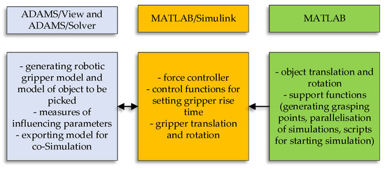
Figure 1.
Simulation model components. Source: own.
A few assumptions were made to reduce the overall complexity of the simulation model: (1) the object pick height is always half of the object depth, (2) rotation of the object is permitted only around the (Y) axis (in the negative direction of gravitational force), (3) only rigid objects and rigid robotic fingers were considered.
Despite those assumptions, the model still qualifies as applicable to a number of real-world bin-picking problems. The user must first input a 2D top-down image of the analyzed object to evaluate selected object pick-points. The best practice is to use a snapshot of the 3D model with a clear distinction between the background and the model since several calculations (generation of pick-points, collision checks, etc.) rely on the correct image segmentation process. Further, the user must specify the input parameters of the selected 2-F robotic gripper (finger width, finger depth, stroke width, etc.) for the model to function correctly. Parameters for the P force controller must be set beforehand, although the user can fine-tune them if needed. Next, the number of pick-points must be assigned if the “Normal” simulation mode is selected. Otherwise, the maximum number of points is set if the simulation mode is set to “Optimization.” In this mode, the user must also specify the successful grasp quality metric (see Section 4.2. for more details) by which the pick-points are considered valid. Pick-points are then generated dynamically, and simulations are run until the selected number of successful pick-points is generated.
3.1. Modeling Robotic Gripper
By importing the 3D model of the robotic gripper from the manufacturer into the ADAMS/View, we can be sure that the dimensions are correct and that there will be no deviations due to the geometry of the 3D model. Next, joint types were assigned to each part (joint) of the robotic gripper, where two or more elements come into contact (Figure 2). Since all joints on the robotic gripper can only move rotationally around their axis, a revolute type of joint was used. This joint type has only one degree of freedom (DoF). Friction in the joints was neglected.
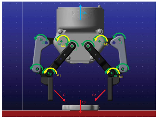
Figure 2.
Model of robotic gripper and the object to be gripped in ADAMS/View. Green arrows (J1–J10) indicate revolute joints, yellow arrows (M1–M4) show rotational motions, cyan arrow (M5) indicates general motion (translation and orientation of the gripper), and red arrows indicate three different contacts used (C1–C3). Source: own.
The robotic gripper is a five-link mechanism, meaning it must be actuated in two joints simultaneously to allow the fingertips of the robotic gripper to move linearly. The mechanism is internally linked without intermediate gears with different gear ratios, which means that the set velocity in the first and second joints must be the same to achieve linear fingertip movement.
Lastly, the mass properties of the robot gripper or its individual elements were determined by selecting the appropriate materials in ADAMS/View. The moments of inertia and mass are calculated through the model’s geometry. Additionally, a body consisting of various materials can be modeled. However, parts with the same material properties must first be divided in the CAD modeling software and then imported to ADAMS piece by piece. Steel was selected for all components of the robotic gripper except the robotic fingers. For the fingers of the robotic gripper, a nitrile-butadiene rubber (NBR) with a density of 1.5 g/cm3 was selected according to the robotic gripper manufacturer’s specifications. The ADAMS/View interface is shown in Figure 3.
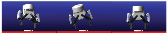
Figure 3.
Model of robotic gripper and the object to be gripped in ADAMS/View with different rotation settings. Source: Own.
3.2. Modeling Gripped Object
Similarly, to modelling of the robotic gripper, the 3D model of the object to be gripped was also imported into ADAMS. The object was 3D scanned and postprocessed in a way that can be imported into the ADAMS/View software. Contact forces between the object and the surface and the static and dynamic friction were defined. We also defined the contacts between the robotic gripper’s left finger and the object gripped along with the right finger. The contact theory used in the simulations in ADAMS is based on Hertzian Contact theory. Figure 4 shows a friction grip model, where each robotic gripper’s fingers supply half of the required contact force.
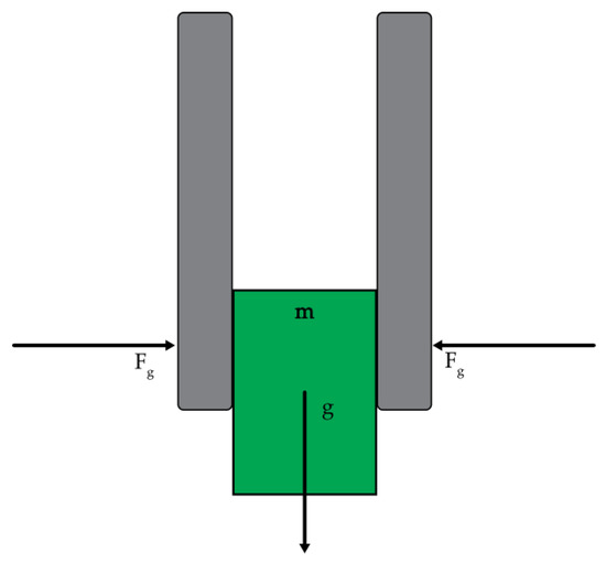
Figure 4.
Friction grip model according to Coulomb’s friction model. Source: own.
The minimal required grasping force, , applied by the gripper to the load can be calculated via the following equation:
where m = mass of the object, g = gravitational acceleration (9.81 m/s2), Sf = safety factor, and μs = static friction coefficient.
Of course, the minimal required grasping force increases as soon as the robotic gripper starts moving. The most significant factor in calculating the required grasping force is correctly determining the friction coefficient.
Tables of friction coefficients between the individual elements were found in ADAMS Help section of the program, and the other parameters were set according to the real-time response of the simulations. Once the initial model and contact forces were established, measures were added to the model to check the influencing parameters (e.g., friction, contact forces, etc.). In addition, a marker was attached to the fingertip of the two-finger gripper to observe the object’s distance from the surface. Furthermore, the object’s rotation around the Y-axis was measured. Angular velocity and contact force measures were attached to the left and right robotic gripper fingers. Those variables served as the input of the force controller of the gripper closing. In our model, we defined the following input variables, which are managed via MATLAB/Simulink: (a) the closing speed of the left and right robotic gripper, (b) the final height of the robot gripper, (c) the start and end time of the robotic gripper, (d) initial speed of the robotic gripper, and (e) the initial translation and the rotation of the robotic gripper. The special feature of these variables is that they can be modified at run-time in MATLAB/Simulink. The initial location and orientation of the object and the robotic gripper can be set before the simulation starts by using the “General Point Motion” on the specific part(s) (Figure 5). However, we found that the model works best if the gripper’s location and orientation are set using the MATLAB/Simulink variables, while the object’s location and orientation are set manually by modifying the batch script (.adm file) prior to the simulation. Therefore, ADAMS models are changed using the MATLAB script by modifying ADAMS model files before running each simulation.
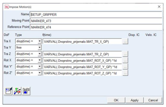
Figure 5.
Translation and rotation settings of the robotic gripper in ADAMS/View. Source: own.
While it is possible to obtain the coefficients of friction between the materials from the existing coefficient of friction tables, it is difficult to determine them accurately in a physical system. In addition, ADAMS models the transition from static to dynamic friction modes continuously rather than as it happens in reality (by jumping from one friction mode to another).
By correctly setting the stiction transition velocity (the velocity at which the static friction is enabled) and friction transition (the velocity at which the static friction turns into dynamic friction mode) velocity parameters, we can obtain a good approximation of this phenomenon.
Table 1 shows model contact parameters, where CLF-O indicates the contact force between the left robotic finger and the object, CRF-O is the contact force between the right robotic finger and the object, and CO-G is the contact force between the object and the surface.

Table 1.
Model contact parameters. Source: own.
3.3. ADAMS/MATLAB Cosimulation
Preparing the model for cosimulation requires assigning input and variables for exporting created during the modeling of the robotic gripper and gripped object. Once satisfied with the model, it was exported via ADAMS/Controls extension in the form of two ADAMS models and a MATLAB script required for generating the Simulink model. The first one has a “.adm” extension, which allows us to run the model simulations in ADAMS/Solver (batch mode). Animation is not shown during the simulation process, as simulation results are written in several results files for later visualization and analysis. It uses considerably fewer computer resources, meaning the simulation time is significantly lower than those generated in ADAMS/View. The second model has a “.cmd” extension and supports an interactive simulation mode, allowing real-time animation of the model’s operation to be shown. Via MATLAB script, an ADAMS system model (written in the form of Level 2 S-Function) is generated, which is then transferred to the simulation model generated by the user.
3.4. Robotic Gripper Force Controller
To approximate the movement of a 2-F robotic gripper closing, the movement of both fingers is controlled by a P force controller. The reference value of the force controller is the desired contact force between the finger of the robotic gripper and an object to be gripped, expressed in Newtons (N). The output of the force controller, which is limited by [−lim, lim], is the robotic gripper closing speed, given in (°/s) since the joints are rotational. The output of the force controller is connected to the input ports of the ADAMS model. Both fingers of the robotic gripper are controlled simultaneously, multiplying the amount of output speed by (−1) for the right finger due to the clockwise direction of the joint’s rotation. The control scheme is shown in Figure 6, and the full Simulink model is shown in Figure 7.
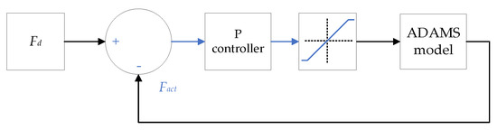
Figure 6.
Force P-controller used to control the closing of robotic grippers’ fingers. Fd is the desired value of contact force between the robotic grippers finger and the object, and Fact is the actual contact force.
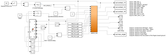
Figure 7.
MATLAB/Simulink control diagram. Source: own.
For tuning the force controller, the Ziegler–Nichols method was used. Due to the settings of the controller (at the beginning, the P part must be large enough for the system to react quickly and, at the end, small enough not to cause any overshoot), a compromise was sought between the two values, which resulted in a slow closing of the gripper, but avoided the subsequent rapid response of the controller. Still, the closing velocity remained in the boundary of the actual gripper closing velocity. The parameters of the force controller are presented in Table 2. The problem with higher values of the P part of the controller occurs mainly after a longer grasping time, as the minimal change in velocity causes the object to slip out from under the robotic gripper. As noted by the Taylor, Drumwright, and Hsu [26], the slipping problem may stem from the simulation tool itself. The issue can be contained to a certain extent but cannot be eliminated. An adaptive controller would allow changing the controller coefficients dynamically according to the current response, further minimizing the slipping of the object.
Table 2.
Force controller parameters. Source: own.
In addition, because of the slip problem mentioned above, we set the condition that as soon as the controller reaches the set contact force, the lifting of the object is started. Otherwise, the object’s slipping begins before it reaches its final height. Figure 8 shows the close-up of the contact force between the left robotic finger and the selected object.
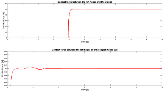
Figure 8.
Selected contact force response (red line) between the left robotic finger and the object to be picked for a sample pick-point, Fd = 50 N. Source: own.
3.5. Generating Pick-Points
With each new simulation, a new pick-point point must be defined, which is entered into the ADAMS model (.adm) using a MATLAB script so that it replaces the part of the code of the ADAMS model that describes the position or orientation of the object. The pick-point described in the following text can be categorized as the pick-point pairs due to the parallel 2-F gripper used. However, for simplicity, the term pick-point will be further used throughout the paper. The pick-point generator generates pick-points pseudorandomly. The points are generated according to the size of the object. The object is initially centered under the two-fingered robotic gripper and can be offset by half its length in two directions (X, Z) in both positive and negative (e.g., +X/−X) and rotated around the (Y) axis. The maximum rotation around the (Y) axis is between 0° and 360°. Since the combination of the three parameters (the height of the gripper is fixed) can set the object out of its feasible gripping range, three checks are performed to ensure that pick-points are viable and valid. This is conducted by importing the top-down view of the object into the MATLAB script, which performs image segmentation and model detection (Figure 9).
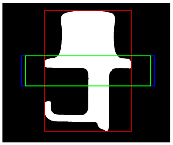
Figure 9.
The test object’s initial position. The blue rectangle shows robotic fingers, the green rectangle is a possible grasping area, and the red rectangle is the object’s bounding box. Source: own.
First, the clearance check is performed, ensuring that the object does not lay directly under each of the two fingertips of the robotic gripper. Second, the portion of the object between the fingertips of the robotic gripper is checked. This is conducted by counting the pixels that are positioned between both fingertips. If the number of pixels covers less than the portion of the entire area set during the setup process, the pick-point is discarded, and the process repeats at the first step. Lastly, the shortest distance between both fingertips of the robotic gripper and the object is calculated. By default, the distance between the fingertips of the robotic gripper is the maximum gripper stroke width, which means that the time required to approach the object varies greatly with the position and orientation of the object. Since the output of the force controller is limited, the gripper takes a long time to close fully. Therefore, we aimed to reduce the needed simulation time so that the fingertips would start close to the object to be picked at the beginning of the simulation.
Since the fingertips of the robotic gripper do not close exactly parallelly (the fingertips of the robotic gripper travel a bit in the (Y) axis direction), we compensated the initial gripper height to ensure that the object is always picked on half of the object height.
3.6. Graphical User Interface
A graphical user interface (GUI) was developed in MATLAB/App Designer (Figure 10), enabling a user-friendly simulation model parameter setup. The application is divided into four tabs, each containing a window for setting various model parameters. If simulations are performed for another object, the model must be reimported into ADAMS/View and re-exported. That is a minor drawback since the 3D model of the object is easily switched in ADAMS/View with the new model. However, the friction coefficients must also be altered based on the object material, yet that is possible to change from within the model GUI. Once the appropriate changes are made, a model of the object must first be imported into the GUI. Since the 3D model cannot be directly imported for further analysis, a top-down picture of the object is imported into the GUI. Using the “Image Processing Toolbox,” image segmentation and object detection are performed. Second, the “Set Gripper Parameters” tab lets the user specify two-fingered gripper stroke width, finger width, and other gripper-related parameters. Additionally, the user can perform test simulations in interactive mode to ensure everything is set up correctly before performing parallel simulations in batch mode. Third, the “Generate input data” tab generates input data points based on the input parameters and starts parallel simulations. In addition, the user can visualize the generated pick-point to ensure correct input parameters. Lastly, the “Analyze results” tab enables visualization of the pick-point and the graph of (contact) forces between the robotic gripper and the object in question. For each pick-point, three metrics are calculated, which correspond to the grasp quality. Since validation of the model is critical to ensure correct model operation, the user can export a selected number of (n) best and (n) worst pick-points in the form of an object positioning template for testing purposes. The template is also valid in the event of rotating the robotic gripper.
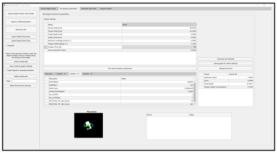
Figure 10.
Graphical User Interface (GUI). Source: own.
Since animations cannot be accessed directly from the model GUI, they can be imported into ADAMS/View. First, a file containing model information (.cmd or .amd) must be loaded into ADAMS/View. Second, in ADAMS PostProcessor, the user must import the graphics file generated during the simulation. From there, it is possible to visualize the entire simulation (animation) of the pick-point evaluation.
3.7. Paralleling Simulations
The simulation time for running the analysis of a single pick-point in ADAMS/MATLAB cosimulation (batch mode) was initially approximately one minute, meaning that a maximum of 1440 simulations could be performed per day. Although the simulations reflect the actual situation reasonably well, the model would not be beneficial if left at this stage, as the simulation time is significantly too long. To this end, we tried to optimize the execution performance of the simulations. All three individual components, the model in ADAMS, the execution of the simulation in MATLAB/Simulink, and the execution of the support scripts in MATLAB, impact the simulation run-time. Since support functions are only run once presimulation, the latter takes a negligible amount of time. Therefore, we focused on optimizing the ADAMS and MATLAB/Simulink models. The simulation time is affected by several parameters: sampling time, numeric integration methods, tolerances on the accuracy of the calculations, etc., which were left at default values. We found that a sampling time of 5 milliseconds is sufficient to run the simulations “quasi-continuously” and that there are no excessive discontinuities between simulation points. We tried to improve the performance of the simulation by employing multiple cores simultaneously. Still, we found that the mechanical ADAMS model works best in a single-core mode when the processor runs at maximum clock speed. In addition, when multiple cores are used, the processing time may increase due to processor context switching. The impact of other parameters in ADAMS has not been studied yet and will be the subject of further analysis.
The run-time dependency of MATLAB/Simulink simulations depends on many factors. Among the most influential are: (a) the run time of the simulations, (b) the integration step, (c) the integration method, and (d) the selected simulation mode. MATLAB/Simulink has a built-in tool for checking the execution time of individual blocks, and it was used to identify blocks that can be replaced or simplified with more time-efficient ones. Using the Model Advisor tool, MATLAB/Simulink can check the optimal integration method and suggest other improvements, including settings for running simulations.
In the following, we found it possible to parallelize the simulations using the “parsim” function. With this function, cosimulations can be run simultaneously depending on the available cores of the computer. MATLAB thus assigns a worker to each kernel to run the simulations. With the help of additional scripts that change the position and orientation of the object in each iteration, each simulation can implement completely different pick-points (with different desired forces, etc.). Parallel simulations are carried out as follows: (1) worker simulation team (pool) is initialized, (2) individual ADAMS models for each of the pick-points are generated, (3) simulation parameters for each model are set, (4) simulations are run in parallel (depending on the number of available workers), (5) the entire team of workers is stopped, and (6) the results are stored and prepared for further analysis.
While using the “parsim” function, a single simulation execution time cannot be shortened; however, running multiple simulations in parallel within a much shorter timeframe is possible. In addition, the input pick-points could be generated on a single computer and then distributed to a cluster of computers if necessary.
3.8. Setting the Correct Mechanical Parameters
Since the quality of the simulation model pick-point success prediction relies on the correct mechanical parameter settings, it is crucial to model those parameters correctly. Several mechanical handbooks [49] and webpages offer approximate friction coefficient settings for various materials, which provide a good starting point. Determining friction coefficients along with the stiffness, force exponent, damping, and penetration depth would require extensive test equipment and much time. Therefore, the graphical user interface for the cosimulation model features a tab from where it is possible to run parallel simulations with different parameters (i.e., parameter sweep). The user specifies the number of simulations, start and end values, and the selected step size. From there, it is advisable that the user prints several paper templates and compares the results from the simulation at specific parameters to the existing system. Usually, the first clue to the correct or inappropriate parameter settings is in the model behavior, visible from the simulation-generated animation. According to the experience gained by the modeling, it is first advisable to change the model stiffness parameter by a decade, followed by a damping setting modification. If those two parameters are set up incorrectly, the model may introduce unwanted jolting or unexpected behavior, such as object disappearing. Lastly, if the contact forces are out of the expected values, it is usually a sign of incorrectly set up gain parameters of the P-force controller. Lower gain values cause the robotic gripper’s fingers to close more slowly but prevent the generation of excessive force.
4. Results
The simulation model for robotic pick-point evaluation for the 2-F robotic gripper was evaluated with two-fold assessments: (a) simulation time evaluation and (b) grasping performance evaluation. The objective of the first test is to determine the execution time of the simulation model in single and parallel modes. In contrast, the second test directly evaluates the performance of the simulation model compared to its physical experiment with the collaborative robot UR5e, 3D Pickit vision system, and 2-F robotic gripper.
4.1. Simulation Time Evaluation
Several tests were conducted to evaluate the time required for the simulations. We assessed the simulations running in a single batch mode and interactive mode by varying simulation time using Parallel Processing Toolbox. Next, 25 simulations were run in parallel, where all the input models (location and orientation of the object) were the same, and lastly, 25 different models were considered. The number of Nsim = 25 was selected due for the time required for subsequent simulations. The simulation time evaluation was performed based on the “hygienic door opener” model, described in the Section 4.2.
Since there is no guarantee that MATLAB will use all the selected workers of the pool in a parallel cluster due to available system resources or possible model errors, we performed five runs for the specified simulation time. However, the average required time for the selected simulation time considers only the three shortest simulation time runs. MATLAB started with the default 12 workers, while this number usually dropped to 9 after executing 25 parallel simulations. The first test runs were performed on a workstation with the following setup: Intel i9-9900K processor, 64 GB DDR4 RAM, Gigabyte nVIDIA GTX 3070 OC, and 1 TB nVMe SSD.
The results of these tests are presented graphically in Figure 11.
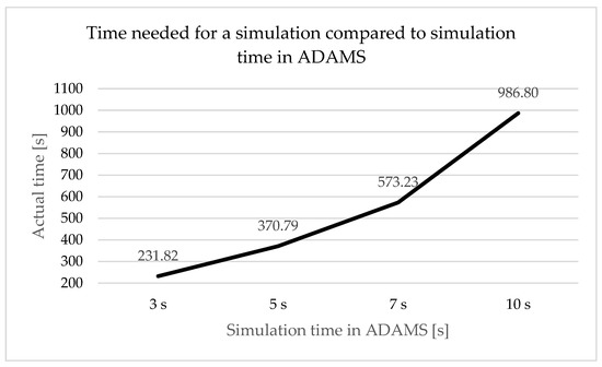
Figure 11.
Time required for running 25 parallel simulations compared to simulation time (3–10 s) with the default number of workers (12). Source: own.
Increasing the number of simulations from 25 to 250 does not scale linearly with the time required for the simulations. As seen from Figure 12, in the event of tsim = 5 s, the average time needed to complete 25 simulations is t = 14.61 s. However, when Nsim = 50 and Nsim = 100 simulations, the time required for a single simulation is t = 13.62 s and t = 12.24 s, respectively. However, it should be noted that the number of workers can drop significantly if more simulations are pending due to possible model errors. On the other hand, the time required for a single simulation also drops significantly with the increase in the total number of simulations.
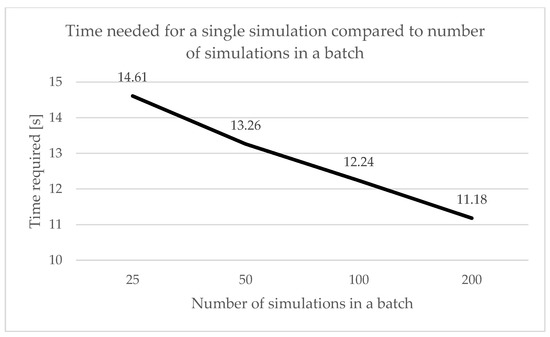
Figure 12.
The time needed for a single simulation compared to the total number in a batch. Source: own.
The time to run a single simulation (in the initial position and orientation) in both modes, normal simulation mode and “ode3” numerical integration method with simulation time tsim = 3 s and integration step Ts = 5 milliseconds, is about t = 53 s in batch mode and about t = 97 s in interactive mode. It must be emphasized that the simulation may take different amounts of time for different pick-points due to the number of (contact) recalculations required.
Under the same simulation conditions, we could run around 600 simulations in 45 min in a batch mode (around 100 simulations for interactive mode) using this function, which equates to around t = 4.5 s per simulation. This would allow us to run around 19,200 simulations in 24 h, almost 13 times the initial simulations. At the same time, we significantly exceeded our target for run-time per simulation.
4.2. Performance Evaluation
To elaborate on the accuracy of our simulation model, we selected a “hygienic door opener” object, on which we performed pick-point analyses for the selected robotic gripper. We conducted 50 pick-point evaluations for the chosen object with our simulation model by varying the object’s translation and rotation. For each pick-point, we elaborated on grasp quality, a metric derived from three pointers: (a) normalized grasp duration (tgrasp), (b) rotation around the main (Y) axis , and (c) the time of absence of contact force between the object and the surface during a successful grasp . Normalized grasp duration (tgrasp) is a metric derived from the time contact force between when the gripper fingers and when the object reaches the desired value and then drops back to zero. The rotation (between 0 and 180) around the main axis (Y) indicates that the set and the actual pick-point are not equal, meaning that it is best to avoid such pick-points since we cannot be sure if the pick-point will be reached.
The total grasp quality score for the selected pick-point for a single object can be expressed as:
where is the grasp quality (score) for the selected pick-point, tgrasp is normalized grasp duration, is rotation around the main (Y) axis, and is the time of absence of contact force between the object and the surface during successful grasp.
After the simulations were completed, we selected ten pick-points which had the highest grasp quality (highest score) and ten with the lowest grasp quality (lowest score). To validate the simulation model, we performed the picking of the object in those pick-points and compared the simulation results with a physical robotic cell workstation. Initial verification of the simulations was carried out by comparing the visual response of the actual bin-picking robotic cell workstation with the simulation model. Still, additional measurement equipment will be needed for accurate verification.
The object had to be placed in the same exact location as in the simulation model, which was achieved with a preprinted template. The template was exported from the GUI and placed directly underneath the robotic cell workstation’s robotic gripper. This ensured that the pick-points were set identically in the simulation and physical setup, preventing false input data.
4.3. Test Procedure
A collaborative robot UR5e with a Robotiq 2-F gripper FT-85 was used to elaborate on the simulation data. Additionally, a 3D-printed template holder was mounted on the robot table to ensure that the object stayed in place during the pick-point evaluation procedure (Figure 13).
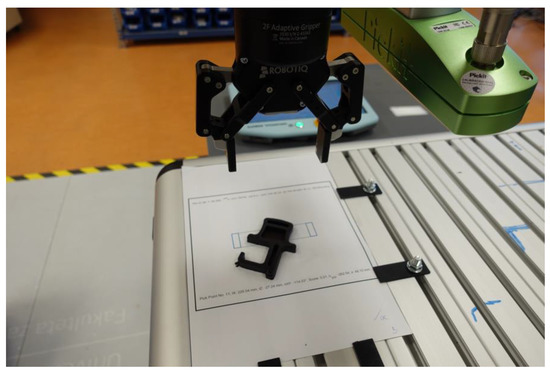
Figure 13.
The test setup consists of UR5e collaborative robot, a Robotiq FT-85 2-F gripper, a 3D-printed template holder, and a paper-printed position template. Source: own.
The Robotiq FT-85 2-F gripper allows the grasping force to be set between 20 and 235 N. The contact force could not be verified this time since we do not possess the force/torque sensor. The grasping force and gripper closing velocity can be set programmatically. Therefore, we decided to set the gripper to the lowest velocity and around 25% of the maximum force. According to manufacturer specification, this would mean that the gripper will grasp the object with approximately 50 N grasping force with a closing velocity of 20 mm/s.
For each of the selected pick-points, the robot arm’s initial height had to be modified manually to account for the robotic gripper fingers moving downwards during robot fingers closing.
First, the robotic gripper was positioned h = 10 cm above the object. After the gripper approached the object with a linear motion, the gripper attempted to grasp it. If the grasping is successful, the object is lifted for h = 10 cm above the robot table and then dropped toward the table. This procedure was repeated five times to account for the possible (minimal) offset between the actual and the set object location.
4.4. Test Object: Hygienic Door Opener
The initially tested object is a hygienic door opener, which has the same height across the entire object base surface. It can be characterized as semicomplex with several distinct features, making it appropriate for the initial testing. Additionally, its similar shape can be easily replicated with 3D printing technology for testing purposes. Table 3 shows the object along with several other parameters. The authors can provide the results of the extensive simulation and verification tests, along with the supplementary data (videos, animations), upon request to encourage additional testing of the object.
Table 3.
The test object. Source: own.
Out of the 20 selected pick-points (from 50 simulations), the initial testing results show that the simulation model correctly determined if the pick-point would be successful in 75% (15 pick-points) of the cases. This indicates that the mechanical parameters of the model are set accordingly. Table 4 shows the results in more detail.
Table 4.
Simulation results. Source: own.
To further elaborate on the grasp quality, three sample pick-points were selected to be directly compared in various stages of grasping in simulation and its physical counterpart. Table 5 shows selected pick-points and their displacement parameters–translation around the (X) and the (Z) axis along with rotation around the (Y) axis. The initial position is shown in Figure 9.
Table 5.
Test pick-point location, orientation, and score. Source: own.
4.4.1. Analysis of Pick-Point N1
Figure 14 shows four steps in picking the selected object in the specific location and orientation: (1) prepick, (2) establishing initial contact with the robotic fingers, (3) reaching final contact, and (4) lifting of the object. In the event of the first pick-point, it can be seen that the gripper cannot pick the object successfully in simulation and on the physical test setup. The grasp score for the first pick-point is also low compared to two successful pick-points, indicating that the success metrics are calculated accordingly. Only in the last step are there minor differences between the simulated and the actual response due to the immediate lifting after establishing contact with the physical system. Therefore, the two figures do not match completely. Figure 15 shows contact forces at the described events for pick-point N1.
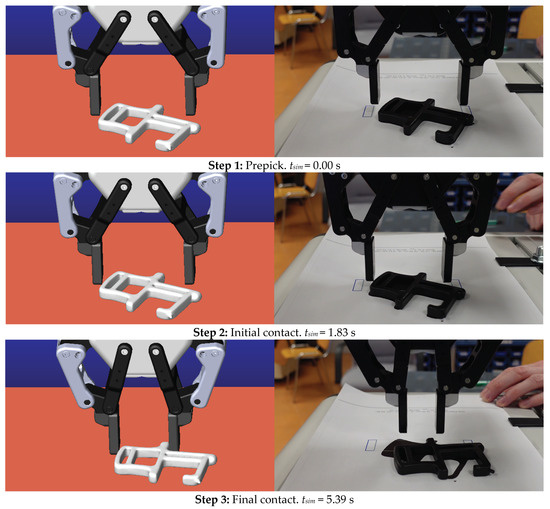
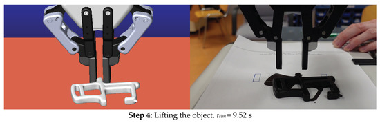
Figure 14.
Graphical analysis of the first pick-point. Source: own.
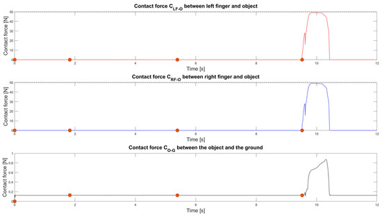
Figure 15.
Contact forces between the left and right fingers and the object (red and blue line), and the contact force between the object and the ground (black line) for the first pick-point. The orange circles indicate the events on Figure 14. The dashed line indicates the desired contact force. Source: own.
As can be seen from Figure 14, the robotic gripper starts grasping the object at around tsim = 5.39 s, and the contact force increases to a small value of around CLF-O = 0.05 N. At around tsim = 9.52 s, the initial contact force is increased to around 49 N since the two bodies (the left gripper finger and the object) come into contact. In the next few milliseconds, the force controller controls the contact force and maintains it for another second. However, when lifting the object starts, the object begins to slip from the gripper fingers; therefore, the contact force CLF-O value suddenly drops to zero.
4.4.2. Analysis of Pick-Point N2
From Figure 16, it can be seen that the gripper picked the object successfully in simulation and on the physical test setup. The grasp quality score for the first pick-point is high compared to the first pick-point. The object in the simulation and its physical test setup behaves nearly identically. In the last step, the object starts slipping from the robotic gripper, as explained, due to the P-force controller used. Figure 17 shows the contact forces at the described events for pick-point N2.
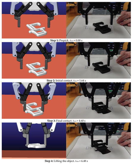
Figure 16.
Graphical analysis of the second pick-point. Source: own.
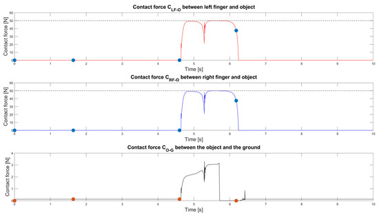
Figure 17.
Contact forces between the left and right fingers and the object (red and blue line), and the contact force between the object and the ground (black line) for the second pick-point. The orange and blue circles indicate the events on Figure 16. The dashed line indicates the desired contact force. Source: own.
As can be seen from Figure 16, the robotic gripper starts grasping the object at around tsim = 4.60 s. The contact force CLF-O and the CRF-O increases to around 50 N. The object is successfully grasped between tsim = 4.60 s and tsim = 6.20 s, as indicated by the nonzero contact force between the object and the surface. Around tsim = 5.70 s and tsim = 6.20 s, the contact force Co-g becomes zero since the object is lifted from the surface. However, due to the slipping problem mentioned above, the force Co-g increases back from zero to the object’s force of gravity. In the physical test setup, the object is successfully grasped, yet in the simulation, it drops only a few seconds after being grasped.
4.4.3. Analysis of Pick-Point N3
Figure 18 shows that the gripper can pick the object successfully for only about a portion of the second in the simulation and on the physical test setup, performing nearly identically. The pick-point score for the first pick-point is close compared to the second pick-point, yet a little lower. This analysis shows that this behavior can be closely and precisely simulated, while the slipping problem described above has reasons in the P controllers setting. Figure 19 shows the graphs of contact forces for pick-point N3.
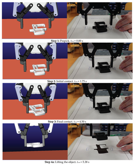
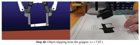
Figure 18.
Graphical analysis of the third pick-point. Source: own.
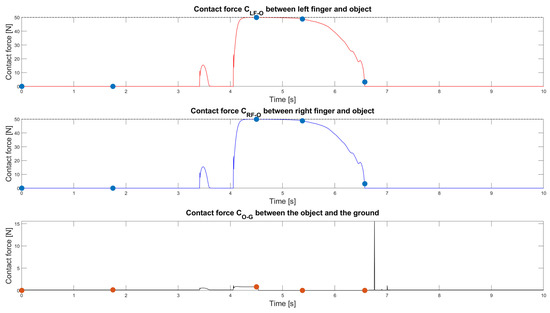
Figure 19.
Contact forces between the left and right fingers and the object (red and blue line), and the contact force between the object and the ground (black line) for the third pick-point. The orange and blue circles indicate the events on Figure 18. The dashed line indicates the desired contact force. Source: own.
As can be seen from Figure 17, the robotic gripper initiates the contact at around the tsim = 1.75 s and starts grasping the object at around tsim = 4.50 s. The contact force increases to around 15 N while establishing solid contact. Still, it drops to zero a fraction of a second later. Again, in the next attempt, the contact force increases toward 50 N, as the contact surface is different because the object rotated from its initial position. The object is successfully grasped between time tsim = 4.10 s and tsim = 4.50 s, yet not lifted, as indicated by the nonzero contact force between the object and the surface. At a time around tsim = 4.60 s, the contact force Co-g becomes zero since the object is lifted from the surface. At around tsim = 6.75 s, the object drops toward the ground due to the lack of proper friction force between the robotic gripper’s fingers and the object.
5. Discussion
From the selected pick-point analysis, we can conclude that the initial simulation model behaves correctly and, in some cases, replicates the actual physical system to a very close extent. The main advantage of using mechanical simulations to determine pick-points is that we can precisely determine an arbitrary number of object pick-points at different parameter settings (e.g., different force settings, different gripper velocity settings, etc.). Additionally, with the ADAMS/MATLAB cosimulation, complex robotic gripper behavior can be modeled along with variants of 2-F robotic grippers (different finger width/depth, stroke width, etc.) since the model is free to be further developed; however, several modifications to the original model are needed in this case. The model’s main disadvantage is that these types of simulation require exact contact values and other parameter settings, which are difficult to verify without accurate force/torque sensors. Compared to “deep-learning” approaches, the developed simulation model based on physics simulation achieves lower accuracy. However, it must be noted that the accuracy mainly depends on the accuracy between the set and the actual mechanical parameters of the system. In our paper, we discussed the issue of setting the correct parameters via parallel simulations and comparing the results on the physical system. One must note that even the deep-learning approaches require various parameter settings, which may be even more complex than setting the mechanical model parameters since it is usually clear what those parameters represent. Therefore, if the parameters in the simulation would exactly replicate the actual system, then the accuracy of the model would be significantly higher.
Furthermore, the simulation requires more time to be processed since a simulation accurately simulates real-world physics rather than makes assumptions from the RGB-D data or point cloud. Anyway, in logistics or production companies, where a single type of product is being bin-picked, such analyses are justified to ensure the high performance of the bin-picking operation. In addition, the simulation model’s inner working shows transparency since we are not using any “black-box” methods. Of course, determining pick-points must be followed with a quality machine vision system to ensure accurate object (and pick-point) detection.
6. Conclusions
Using a simulation model to evaluate pick-points for a two-finger robotic gripper, we proved that it is possible to systematically check the performance of the selected robotic gripper pick-point using cosimulation with ADAMS and MATLAB/Simulink. Since the model does not yet consider variations of the object depth or allow inner grasping, the proposed object allowed us to test the proof of our concept. The initial results (75% of correctly determined pick-points) proved that the simulation model should be further developed to address the variations of the object depth. Although the simulations do not yet match reality completely, we have successfully laid the foundations for further research. Setting the correct contact parameters requires the most attention. Therefore, we will use machine learning methods to automatically (based on the actual system response) select the most appropriate ones. To further verify the simulated pick-points, we will use force gauges to check the magnitude of the contact forces and the consistency of the set parameters in the simulation and its physical test setup. In the following research, we will first focus on improving the performance of existing simulations and visualization of the pick-points in the 3D model and further reducing simulation time by optimizing the various aspects of the model. Furthermore, to confirm the pick-point resilience toward minor imperfections of the vision system information, we propose that the pick-point evaluation takes place in two steps. First, the pick-point generator should generate points randomly, and the simulation model should determine the most appropriate pick-points. Next, those most appropriate pick-points should be further modified with small perturbations to account for the vision system imperfections. If the original and the perturbed pick-points are still valid, then those pick-points can be considered to lead to reliable picking. Additionally, the limitations on object rotation should be addressed since the possible application of the simulation model is now limited to a few specific applications. Additionally, we would like to use other types of robotic grippers, not limited only to two-fingered robotic grippers, such as vacuum grippers, three-finger grippers, and different special types of robotic grippers.
In combination with a selected 3D vision system, evaluating and setting the pick-points using the developed model could be entirely automated, providing reliable information. In the future, we plan to automate the measurements, which we plan to do using an advanced 3D vision system.
Author Contributions
Conceptualization, P.B., D.H. and T.L.; methodology, P.B.; software, P.B.; validation, P.B., D.H. and T.L.; formal analysis, P.B. and D.H.; investigation, P.B.; resources, T.L.; data curation, T.L.; writing—original draft preparation, P.B., D.H. and T.L.; writing—review and editing, P.B., T.L. and D.H.; visualization, T.L.; supervision, T.L. and D.H.; project administration, T.L.; funding acquisition, T.L. All authors have read and agreed to the published version of the manuscript.
Funding
This research work was supported by the Slovenian Research Agency (ARRS) in ARRS Young Researcher Program (Research activity agreement 2018/2019). T.L. and D.H. were supported by the ARRS Applied Research Project (Research activity agreement 2020/21) entitled: “Warehousing 4.0—Integration model of robotics and warehouse order picking systems”; grant number: L5-2626.
Institutional Review Board Statement
Not applicable.
Informed Consent Statement
Not applicable.
Data Availability Statement
All data obtained in this study are available upon request by contacting the corresponding author.
Acknowledgments
The authors would like to thank the entire team of the Laboratory for Cognitive Systems in Logistics at the Faculty of Logistics for their support, useful comments, and suggestions.
Conflicts of Interest
The authors declare no conflict of interest.
References
- Lasi, H.; Fettke, P.; Kemper, H.G.; Feld, T.; Hoffmann, M. Industry 4.0. Bus. Inf. Syst. Eng. 2014, 6, 239–242. [Google Scholar] [CrossRef]
- Xu, L.D.; Xu, E.L.; Li, L. Industry 4.0: State of the art and future trends. Int. J. Prod. Res. 2018, 56, 2941–2962. [Google Scholar] [CrossRef]
- Bousdekis, A.; Lepenioti, K.; Apostolou, D.; Mentzas, G. A review of data-driven decision-making methods for industry 4.0 maintenance applications. Electronics 2021, 10, 828. [Google Scholar] [CrossRef]
- Moeuf, A.; Pellerin, R.; Lamouri, S.; Tamayo-Giraldo, S.; Barbaray, R. The industrial management of SMEs in the era of Industry 4.0. Int. J. Prod. Res. 2018, 56, 1118–1136. [Google Scholar] [CrossRef]
- Zhong, R.Y.; Xu, X.; Klotz, E.; Newman, S.T. Intelligent Manufacturing in the Context of Industry 4.0: A Review. Engineering 2017, 3, 616–630. [Google Scholar] [CrossRef]
- Barreto, L.; Amaral, A.; Pereira, T. Industry 4.0 implications in logistics: An overview. Procedia Manuf. 2017, 13, 1245–1252. [Google Scholar] [CrossRef]
- ten Hompel, M.; Kerner, S. Logistics 4.0: The vision of the Internet of Autonomous Things. Inform. -Spektrum 2015, 38, 176–182. [Google Scholar] [CrossRef]
- Boysen, N.; de Koster, R.; Weidinger, F. Warehousing in the e-commerce era: A survey. Eur. J. Oper. Res. 2019, 277, 396–411. [Google Scholar] [CrossRef]
- Calzavara, M.; Battini, D.; Bogataj, D.; Sgarbossa, F.; Zennaro, I. Ageing workforce management in manufacturing systems: State of the art and future research agenda. Int. J. Prod. Res. 2020, 58, 729–747. [Google Scholar] [CrossRef]
- Statista. Logistics Industry-Market Size 2027. Available online: https://www.statista.com/statistics/943517/logistics-industry-global-cagr/ (accessed on 28 December 2022).
- Statista. Global e-Commerce Market Size 2020–2026. Available online: https://www.statista.com/statistics/1286887/e-commerce-logistics-market-size-worldwide/ (accessed on 28 December 2022).
- WGTL. Intralogistics—Logistics Journal. Available online: https://www.logistics-journal.de/about/intralogistics (accessed on 28 December 2022).
- de Koster, R.; Le-Duc, T.; Roodbergen, K.J. Design and control of warehouse order picking: A literature review. Eur. J. Oper. Res. 2007, 182, 481–501. [Google Scholar] [CrossRef]
- Srinivas, S.; Yu, S. Collaborative order picking with multiple pickers and robots: Integrated approach for order batching, sequencing and picker-robot routing. Int. J. Prod. Econ. 2022, 254, 108634. [Google Scholar] [CrossRef]
- D’Souza, F.; Costa, J.; Pires, J.N. Development of a solution for adding a collaborative robot to an industrial AGV. Ind. Robot 2020, 47, 723–735. [Google Scholar] [CrossRef]
- Azadeh, K.; De Koster, R.; Roy, D. Robotized and Automated Warehouse Systems: Review and Recent Developments. Transp. Sci. 2019, 53, 917–945. [Google Scholar] [CrossRef]
- Bormann, R.; de Brito, B.F.; Lindermayr, J.; Omainska, M.; Patel, M. Towards Automated Order Picking Robots for Warehouses and Retail. In Proceedings of the Lecture Notes in Computer Science (including Subseries Lecture Notes in Artificial Intelligence and Lecture Notes in Bioinformatics); Springer: Berlin/Heidelberg, Germany, 2019; pp. 185–198. [Google Scholar]
- Du, G.; Wang, K.; Lian, S.; Zhao, K. Vision-based robotic grasping from object localization, object pose estimation to grasp estimation for parallel grippers: A review. Artif. Intell. Rev. 2021, 54, 1677–1734. [Google Scholar] [CrossRef]
- Wang, W.; Liu, W.; Hu, J.; Fang, Y.; Shao, Q.; Qi, J. GraspFusionNet: A two-stage multi-parameter grasp detection network based on RGB–XYZ fusion in dense clutter. Mach Vis. Appl. 2020, 31, 58. [Google Scholar] [CrossRef]
- Jiang, S.; Li, S.; Bai, Q.; Yang, J.; Miao, Y.; Chen, L. Research on generation method of grasp strategy based on deeplab v3+ for three-finger gripper. Information 2021, 12, 278. [Google Scholar] [CrossRef]
- Caldera, S.; Rassau, A.; Chai, D. Review of deep learning methods in robotic grasp detection. Multimodal Tech. Inter. 2018, 2, 57. [Google Scholar] [CrossRef]
- Mahler, J.; Matl, M.; Satish, V.; Danielczuk, M.; DeRose, B.; McKinley, S.; Goldberg, K. Learning ambidextrous robot grasping policies. Sci Robot 2019, 4. [Google Scholar] [CrossRef]
- Wu, B.; Akinola, I.; Gupta, A.; Xu, F.; Varley, J.; Watkins-Valls, D.; Allen, P.K. Generative Attention Learning: A “GenerAL” framework for high-performance multi-fingered grasping in clutter. Auton. Robot. 2020, 44, 971–990. [Google Scholar] [CrossRef]
- Lenz, I.; Lee, H.; Saxena, A. Deep learning for detecting robotic grasps. Int. J. Robot. Res. 2015, 34, 705–724. [Google Scholar] [CrossRef]
- Zechmair, M.; Morel, Y. Penalty-based Numerical Representation of Rigid Body Interactions with Applications to Simulation of Robotic Grasping. In Proceedings of the 2022 International Conference on Electrical, Computer, Communications and Mechatronics Engineering (ICECCME), Maldives, 16–18 November 2022; pp. 1–8. [Google Scholar]
- Taylor, J.R.; Drumwright, E.M.; Hsu, J. Analysis of grasping failures in multi-rigid body simulations. In Proceedings of the 2016 IEEE International Conference on Simulation, Modeling, and Programming for Autonomous Robots (SIMPAR), San Francisco, CA, USA, 13–16 December 2016; pp. 295–301. [Google Scholar]
- Open Dynamics Engine. Available online: https://www.ode.org/ (accessed on 10 February 2023).
- Bullet Real-Time Physics Simulation|Home of Bullet and PyBullet: Physics Simulation for Games, Visual Effects, Robotics and Reinforcement Learning. Available online: https://pybullet.org/wordpress/ (accessed on 10 February 2023).
- DART: Dynamic Animation and Robotics Toolkit. Available online: https://dartsim.github.io/ (accessed on 10 February 2023).
- SimTK: Simbody: Multi-body Physics API: Project Home. Available online: https://simtk.org/projects/simbody (accessed on 10 February 2023).
- Erez, T.; Tassa, Y.; Todorov, E. Simulation tools for model-based robotics: Comparison of Bullet, Havok, MuJoCo, ODE and PhysX. In Proceedings of the 2015 IEEE International Conference on Robotics and Automation (ICRA), Seattle, WA, USA, 26–30 May 2015; pp. 4397–4404. [Google Scholar]
- GraspIt! Available online: https://graspit-simulator.github.io/ (accessed on 10 February 2023).
- Malvezzi, M.; Gioioso, G.; Salvietti, G.; Prattichizzo, D. SynGrasp: A MATLAB Toolbox for Underactuated and Compliant Hands. IEEE Robot. Autom. Mag. 2015, 22, 52–68. [Google Scholar] [CrossRef]
- Zechmair, M.; Morel, Y. Assessing Grasp Quality using Local Sensitivity Analysis. In Proceedings of the 2021 IEEE/RSJ International Conference on Intelligent Robots and Systems (IROS), Prague, Czech Republic, 27 September–1 October 2021; pp. 3995–4001. [Google Scholar]
- Le, T.N.; Lundell, J.; Abu-Dakka, F.J.; Kyrki, V. Deformation-Aware Data-Driven Grasp Synthesis. IEEE Robot. Autom. Lett. 2022, 7, 3038–3045. [Google Scholar] [CrossRef]
- Huang, I.; Narang, Y.; Eppner, C.; Sundaralingam, B.; Macklin, M.; Bajcsy, R.; Hermans, T.; Fox, D. DefGraspSim: Physics-Based Simulation of Grasp Outcomes for 3D Deformable Objects. IEEE Robot. Autom. Lett. 2022, 7, 6274–6281. [Google Scholar] [CrossRef]
- Li, M.; Ferguson, Z.A.H.; Schneider, T.; Langlois, T.; Zorin, D.; Panozzo, D.; Jiang, C.; Kaufman, D.M. Incremental Potential Contact: Intersection- and Inversion-free, Large-Deformation Dynamics. ACM Trans Graph. 2020, 39, 49:1–49:20. [Google Scholar] [CrossRef]
- Kim, C.M.; Danielczuk, M.; Huang, I.; Goldberg, K. IPC-GraspSim: Reducing the Sim2Real Gap for Parallel-Jaw Grasping with the Incremental Potential Contact Model. In Proceedings of the IEEE International Conference on Robotics and Automation, Philadelphia, PA, USA, 23–27 May 2022; pp. 6180–6187. [Google Scholar]
- Bonilla, M.; Farnioli, E.; Piazza, C.; Catalano, M.; Grioli, G.; Garabini, M.; Gabiccini, M.; Bicchi, A. Grasping with Soft Hands. In Proceedings of the IEEE-RAS International Conference on Humanoid Robots, Seoul, Republic of Korea, 3–5 November 2015; pp. 581–587. [Google Scholar]
- Utomo, T.W.; Cahyadi, A.I.; Ardiyanto, I. Suction-based Grasp Point Estimation in Cluttered Environment for Robotic Manipulator Using Deep Learning-based Affordance Map. Int. J. Autom. Comput. 2021, 18, 277–287. [Google Scholar] [CrossRef]
- Shukla, P.; Kumar, H.; Nandi, G.C. Robotic grasp manipulation using evolutionary computing and deep reinforcement learning. Intell. Serv. Rob. 2021, 14, 61–77. [Google Scholar] [CrossRef]
- Wang, J.; Li, S. Grasp detection via visual rotation object detection and point cloud spatial feature scoring. Int. J. Adv. Rob. Syst. 2021, 18. [Google Scholar] [CrossRef]
- Vahrenkamp, N.; Westkamp, L.; Yamanobe, N.; Aksoy, E.E.; Asfour, T. Part-based grasp planning for familiar objects. In Proceedings of the 2016 IEEE-RAS 16th International Conference on Humanoid Robots (Humanoids), Cancun, Mexico, 15–17 November 2016; pp. 919–925. [Google Scholar]
- Tian, H.; Wang, C.; Manocha, D.; Zhang, X. Transferring Grasp Configurations using Active Learning and Local Replanning. In Proceedings of the 2019 International Conference on Robotics and Automation (ICRA), Montreal, Canada, 20–24 May 2019; pp. 1622–1628. [Google Scholar]
- Nechyporenko, N.; Morales, A.; Cervera, E.; del Pobil, A.P. A Practical Approach for Picking Items in an Online Shopping Warehouse. Appl. Sci. 2021, 11, 5805. [Google Scholar] [CrossRef]
- Xu, Z.; Qi, B.; Agrawal, S.; Song, S. AdaGrasp: Learning an Adaptive Gripper-Aware Grasping Policy. In Proceedings of the IEEE International Conference on Robotics and Automation, Xi’an, China, 5 June 2021; pp. 4620–4626. [Google Scholar]
- Laili, Y.; Chen, Z.; Ren, L.; Wang, X.; Deen, M.J. Custom Grasping: A Region-Based Robotic Grasping Detection Method in Industrial Cyber-Physical Systems. IEEE Trans. Autom. Sci. Eng. 2022, 1–11. [Google Scholar] [CrossRef]
- Cheng, H.; Wang, Y.; Meng, M.Q.H. A Vision-Based Robot Grasping System. IEEE Sens. J. 2022, 22, 9610–9620. [Google Scholar] [CrossRef]
- Marks’ Standard Handbook for Mechanical Engineers, 12th ed.; McGraw-Hill Education: New York, NY, USA, 2018.


Disclaimer/Publisher’s Note: The statements, opinions and data contained in all publications are solely those of the individual author(s) and contributor(s) and not of MDPI and/or the editor(s). MDPI and/or the editor(s) disclaim responsibility for any injury to people or property resulting from any ideas, methods, instructions or products referred to in the content. |
© 2023 by the authors. Licensee MDPI, Basel, Switzerland. This article is an open access article distributed under the terms and conditions of the Creative Commons Attribution (CC BY) license (https://creativecommons.org/licenses/by/4.0/).