Abstract
A high-resolution infrared (IR) camera was used for temperature measurements in a pharmaceutical formulation (mannitol/sucrose solution, 4:1%, m/m) during a freeze-drying process. The temperature was measured simultaneously at the surface as well as vertically (e.g., in-depth) along the side of custom-made cuvettes equipped with a germanium (Ge) window. Direct imaging during 45 h from −40 °C to 40 °C took place every 60 s on the surface and on the side with 0.28 × 0.28 mm per IR-pixel providing 2700 thermograms. The spatial resolution per cuvette was approximately 4225 pixels for the surface view (without a probe) and 6825 IR-pixels for the side view. Temperature effects and gradients due to the presence of a Pt100 and a LyoRx-probe in the pharmaceutical formulation were clearly visible and were quantified during the freezing step as well as the primary and secondary drying stages. The temperature was about 3.5 K higher during primary drying as compared to the temperature measured in the same material in adjacent cuvettes without probes. During secondary drying, evaporative cooling of upper layers was clearly visible.
1. Introduction
Freeze-drying is a highly appropriate methodology for drying thermally labile products and matrices. Due to its relatively high operational cost, it is mainly used for drying products with high intrinsic values such as pharmaceutical products, e.g., drugs, proteins and vaccines, as well as food commodities [1,2]. For monitoring the product’s temperature during a freeze-drying cycle, a few probes are in most cases directly placed in the materials undergoing drying. The types of probes used in this work were a Pt100 sensor to measure temperature and a LyoRX sensor to measure resistivity and temperature in the material (integral parts of the freeze-drying instrument) [3]. Pt100 sensors are resistance thermometers that normally have a resistance of 100 ohm at 0 °C, whereas the LyoRX measures resistance between two pin-electrodes (The LyoRX is a brand name of Martin Christ, Osterode, Germany). This is the main feature of this sensor, although it also incorporates a Pt100 sensor to measure temperature. A value of 100% resistivity is indicative of a frozen material in which no current can flow between the pins. The direct contact between the probes and the material has certain drawbacks. First, it is a single-point measurement, and second, the presence of the probe itself affects the drying process [4]. In two previous articles from 2014 and 2022, Emteborg et al. described the coupling of an IR camera to a freeze-dryer, thereby measuring the product temperature contact-free and with superior spatial resolution [5,6]. The work from 2014 described the first application of this kind [5]. Additional papers were subsequently published by other authors, who also made use of infrared cameras to monitoring the freeze-drying processes using a variety of configurations of IR cameras and freeze-dryers. For example, some of the reports described operating the IR camera inside the freeze-drying chamber and others reported measuring directly onto glass surfaces that are not transparent to IR radiation [7,8,9,10,11,12,13,14].
The first two publications by Emteborg made use of an IR camera with a microbolometer limited to 320 × 240 pixels and a 25 mm wide-angle lens that covered a field of view of approximately 30 × 40 cm, which corresponds to the size of a freeze-drying tray [5,6]. The references [5,6] contain detailed schematics of the experimental setup used in this work. The second article from 2022 specifically addressed a shortcoming of the first work, namely, that only the surface temperature could be monitored. The new development allowed monitoring along depth profiles (e.g., a side view) using custom-made cuvettes with a Ge-window [6]. Limitations of the spatial resolution of the IR camera’s sensor and its lens were nonetheless apparent as only 84 pixels could be used for monitoring the side and 64 pixels for monitoring the surface view of the cuvettes. Despite its relatively low spatial resolution, it is still superior to the Pt-100 probes, which provide only one measurement point that, additionally, is not contact-free. Roy and Pikal established a long time ago that the presence of probes in the material increases the ice-nucleation temperature as well as the primary drying speed. Vials with probes consequently finished primary drying earlier than similar vials without probes [4]. Other contact-free approaches have been reported; for instance, Jiang et al. published a paper about the monitoring of temperature along depth profiles whereby strips with five sensing elements were attached on the outside of glass vials during freeze-drying [15]. However, when using this approach, the temperature readouts are compromised by an averaged temperature as the temperature is measured on the outside of the glass vials. This effect also prevails when IR cameras are used for measurements of temperature on the outside of glass vials, although IR-thermography clearly provides superior spatial resolution [8]. However, when combined with the custom-made cuvettes equipped with one side made of germanium as reported previously [6], minute differences in temperature and positions can be recorded at the surface of the material itself adjacent to the Ge-window inside the cuvette.
In the current study, a new IR camera with a 640 × 480 pixel microbolometer and 40 mm lens was coupled to a freeze-dryer and used together with the custom-made glass cuvettes with one side made of germanium [6]. This set-up allowed the monitoring of the gradual change in temperature through a full freeze-drying cycle based on 2700 thermograms with a field-of-view of about 140 × 180 mm. The side view of these cuvettes (filled with formulation) was approximately 18 × 30 mm (65 × 105 IR-pixels), resulting in approximately 6825 IR-pixels, which is an 80-fold increase in comparison with previous work. The surface view consisted of 4225 pixels in cuvettes without a probe, and it was exploited for comparing and quantifying the thermal effect that the presence probes had on the material during ice-nucleation, freezing and primary drying. If a probe is present, part of the surface view was not visible because of the wires, and the number of available pixels was reduced somewhat. The resolution and thermal images were of sufficient detail to reveal temperature gradients near the probes and across the surface, especially during primary drying. To our knowledge, this is the first time it has been possible to clearly display and measure the temperature differences prevailing around probes during a freeze-drying cycle. Attention was paid not to monitor the wire of the probes still making sure that meas-urements took place as close as possible to the probes. The probes were immersed about 8 mm into the pharmaceutical formulation in order to obtain a measurable temperature effect closer to the surface using the IR camera. The probes were consequently not placed at the bottom of the vial, which would be the most logical position [4]. The Pt100 probe is a small metal cylinder of 3 mm diameter and 6 mm height. It occupies a volume of 42 µL and thereby makes up about 0.5% of the total fill volume of pharmaceutical formulation. The LyoRX probe is also a cylinder (equipped with two pins) but is made of a polymer material. It has a diameter of 6.5 mm and a height of 9 mm. It occupies a volume of 300 µL and thereby makes up about 3.5% of the total fill volume of pharmaceutical formulation. For both sensors, the connecting wires were not considered when calculating their volumes (present inside the material). Monitoring took place on the material next to the wires, whereas the bulk of the sensor was below the surface. The current work also provides a better resolution of local temperature differences along the depth profiles (e.g., of the side view) during a drying cycle as compared to previous work [6]. The freeze-drying cycle employed here consisted of the four steps listed below, and any freeze-drying cycle must always consist of steps 1, 3 and 4.
- Freezing of the water present in the matrix at ambient pressure (without causing severe phase separation and too-small ice crystals. The ice-nucleation temperature and uniform freezing conditions are crucial for achieving excellent and uniform product quality after drying [16,17])
- Annealing of ice to achieve crystals of larger and uniform size [18].
- Sublimation (primary drying), whereby the water evaporates from solid ice in the material and is captured on the ice-condenser under soft vacuum.
- Secondary drying during which most of the remaining water is removed under hard vacuum and a shelf temperature of 20 to 30 °C.
2. Materials and Methods
An IR camera (VarioCAM HDx head S 625, Jenoptik, InfraTec GmbH, Dresden, Germany) was mounted vertically, with the lens facing downward looking through a round Ge-window placed in the vacuum chamber wall of a freeze-dryer (Epsilon 2-100D, Martin Christ, Osterode, Germany) [5,6]. The IR camera was equipped with a 40 mm lens providing a field of view of approximately 140 × 180 mm. The VarioCAM HDx camera has a 640 × 480 pixel microbolometer measuring in the 7.5 to 14 µm LWIR interval and has a thermal resolution better than 40 mK in a range from −40 °C to 600 °C. The temperature range employed in this work ranged from −40 to 40 °C. Calibration (temperature accuracy checks) at the factory revealed a deviation of 0.0 K at −7.7 °C and 0.1 K at 23.5 °C compared with black-body radiators and a calibrated pyrometer. The stainless steel top shelf in the freeze-dryer that was partially monitored by the IR camera was coated with masking tape (3M type 101E) using 50 mm wide strips that had been neatly placed next to each other. The shelf temperature could therefore be directly monitored using the IR camera because the tape layer is drastically increasing the emissivity. A value of 0.93 for emissivity was applied throughout data treatment in the dedicated software (IRBIS 3 Professional, Jenoptik). The IR camera recorded images of the material in the Ge cuvettes as well as the shelf of the freeze-dryer with a high spatial resolution (0.28 × 0.28 mm). A prism (IR-mirror) with a 45° angle (Umicore Electro-Optic Materials, Olen, Belgium) was placed next to five cuvettes to monitor the side of the cuvettes with the IR camera looking from above. Furthermore, D-mannitol (>98% pure) and sucrose (>99.5% pure) were obtained from Sigma Aldrich (Steinheim, Germany) and dissolved in Type-1 water (18.2 MΩ cm, 0.053 μS cm−1, Merck Millipore, Billerica, MA, USA) to obtain a mannitol/sucrose solution, 4:1%, (m/m). Additional information and detailed figures about this setup can be found in previous works [5,6].
After freeze-drying, the water content of the mannitol/sucrose formulation was measured in each of the five cuvettes using volumetric Karl Fischer titration (Metrohm, Herisau, Switzerland).
The freeze-drying cycle for the formulation was controlled and monitored using machine readings of shelf temperatures, product temperatures and pressure. The freeze-drying program can be deduced from those readings and is therefore not reported separately. Product temperature and resistivity readouts (Lyo RX) were obtained from a Pt100 probe or LyoRX probe immersed in the product and connected by a wire to the freeze-dryer as discussed before.
3. Results and Discussion
In Figure 1a, an IR-thermogram and the measurement areas of the surface and the side views of five cuvettes and the shelf temperature are shown as R1 to R16 (Irbis 3.1 professional software denotes these geometries as rectangles even though they are squares). In Figure 1b, a photo is shown of the same setup with the final dried product, the five cuvettes, the position of the probes and the IR-mirror. The spatial average temperature of R1 to R5 and R16 was used to prepare Figure 2, displaying the surface temperature of cuvettes 1 through 5 throughout the freeze-drying cycle and the shelf temperature. Machine readings of shelf-temperature, pressure, product-temperatures, resistivity and ice condenser temperature are shown in Figure 3 for comparison, which is a graphical representation of the freeze-drying program. The emissivity correction for all thermograms of 0.93 was deduced by matching the readout of the average shelf temperature from the freeze-dryer and from the rectangle shown in Figure 1 (R16) using the IR-camera. In Figure 4a,b the nucleation and sublimation behaviour of the mannitol/sucrose solution is shown. In Figure 5a–d, thermograms are shown for different stages of the freeze-drying programme displaying the measurement profiles (line 1 to line 5) of the surface temperature. A measurement line in the thermogram offers the possibility of displaying a temperature profile across the cuvette’s surface. Each temperature readout is given per pixel, which here translates to every 0.3 mm. The temperature readout of these profiles are shown as a function of position at the cuvette’s surface in Figure 6a–d, respectively. Finally, Figure 7 shows a thermogram of cuvettes 1, 2 and 3 next to each other, clearly showing the superior spatial resolution in comparison to the previous work during the primary drying (sublimation) [6]. Each of the different figures summarised here are discussed in more detail below. Additional figures are also available in the electronic Supplementary Materials Figures S1–S6 and are described there separately.
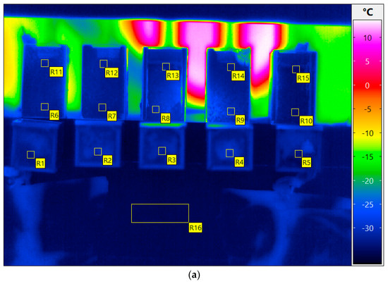
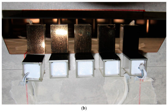
Figure 1.
(a) The cuvettes are denoted as 1 through 5 from left to right in all descriptions in the current work. Measurement definitions are R1 to R16. R1 to R5 correspond to direct measurements at the surface. R6 to R15 are measurement definitions at the side on the germanium window in the reflection on the IR-mirror, and R16 is a direct measurement of the shelf temperature using the IR-camera. (b) Photo from above of the five cuvettes standing on the freeze-drying shelf coated with masking tape. The white material is freeze-dried product. The IR-mirror (gold-coated prism) in which the five cuvettes are reflected is at the top. To the left, a Pt100 probe and to the right, a Lyo RX probe are visible in the dried product.
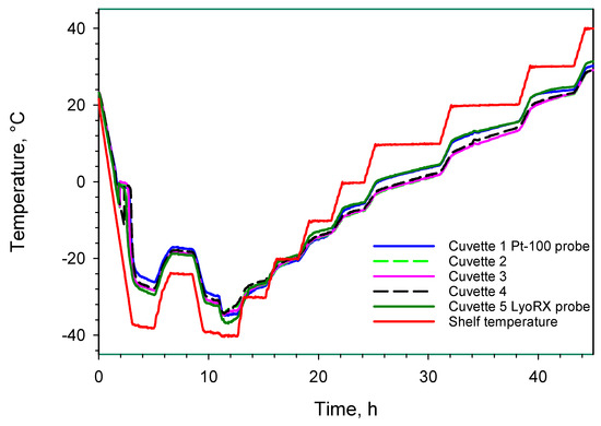
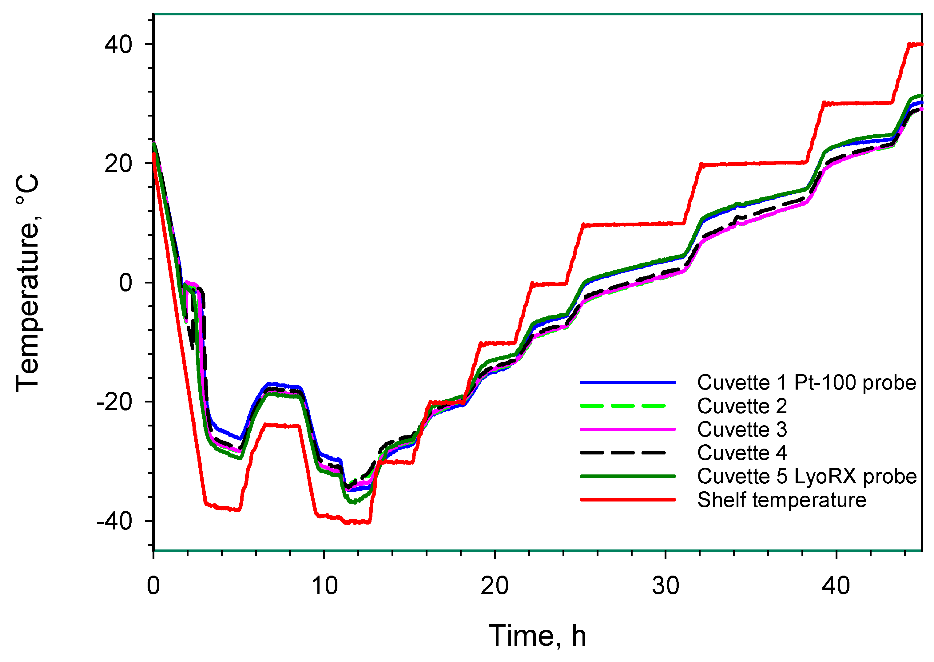
Figure 2.
Entire freeze-drying process: surface view with and without probes using average temperature readouts from R1 to R5 and R16.
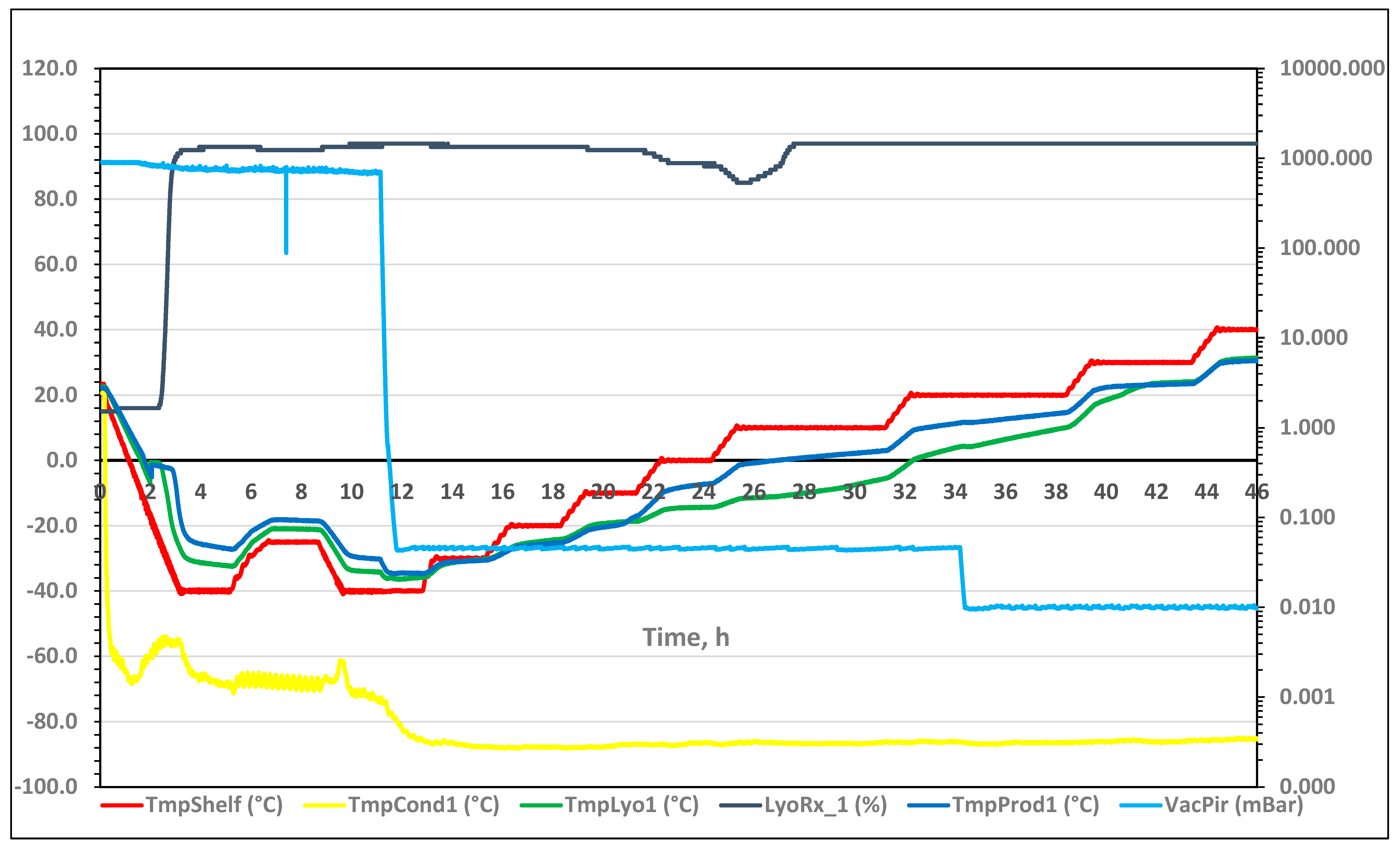
Figure 3.
Full freeze-drying cycle of the pharmaceutical formulation based on machine readings of product temperature from Pt-100 sensors (TmpProd1 and TmpLyo1), shelf-temperature, pressure (VacPir), ice-condenser temperature and resistivity (Lyo-RX, displayed in %, left y-axis).
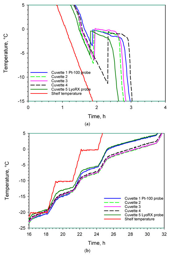
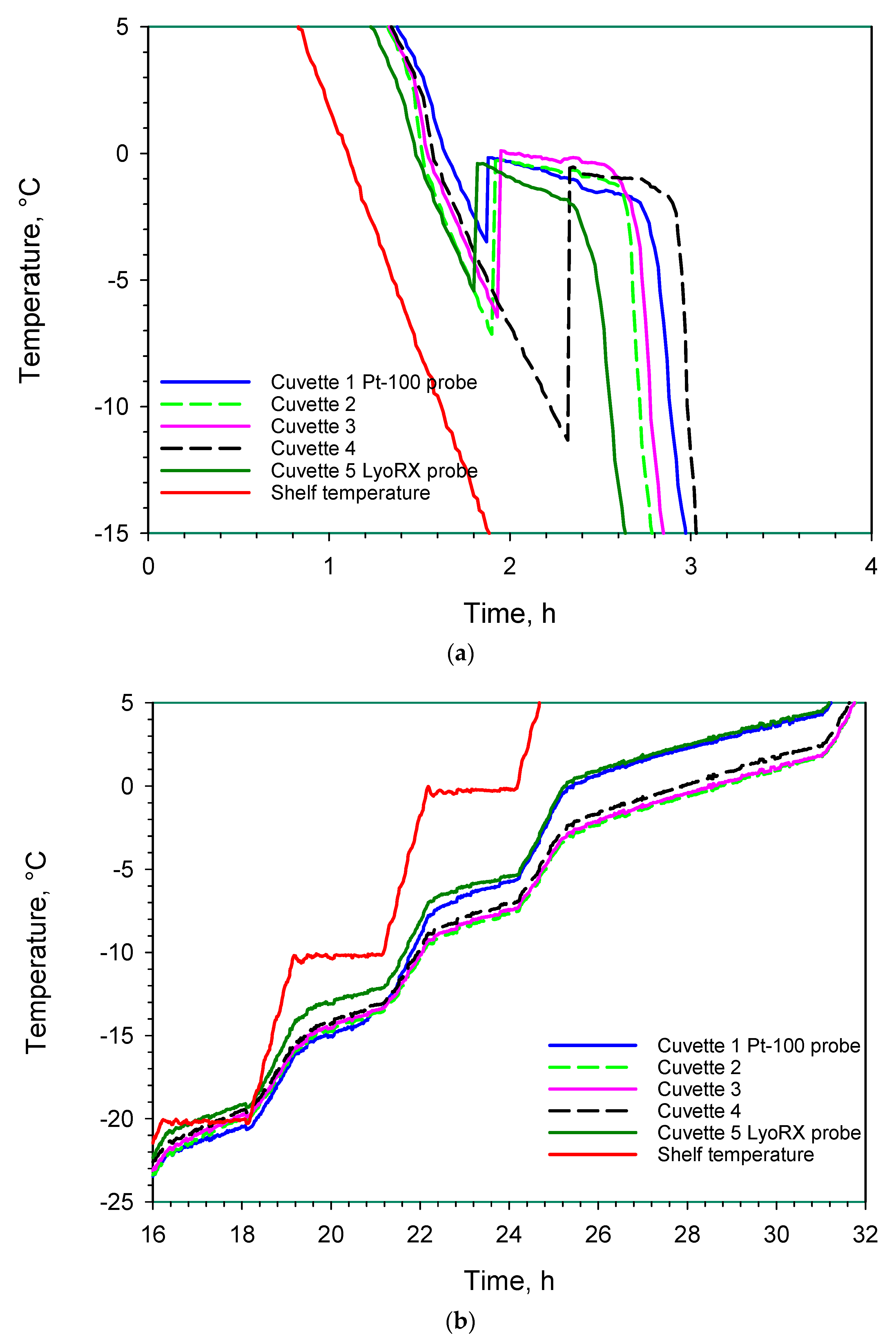
Figure 4.
(a) Surface measurements of average temperature using R1 to R5. The nucleation temperatures can be seen at the dip of each measurement area around 2 h on the y-axis, with the respective time of nucleation on the x-axis. (b) Speed of primary drying (with different slopes) and difference between cuvettes with and without probes for surface measurements of temperature using R1 to R5.

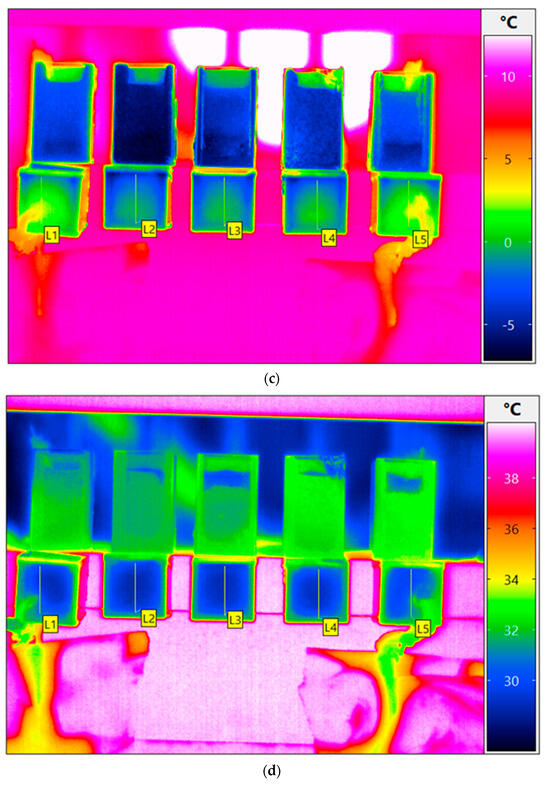
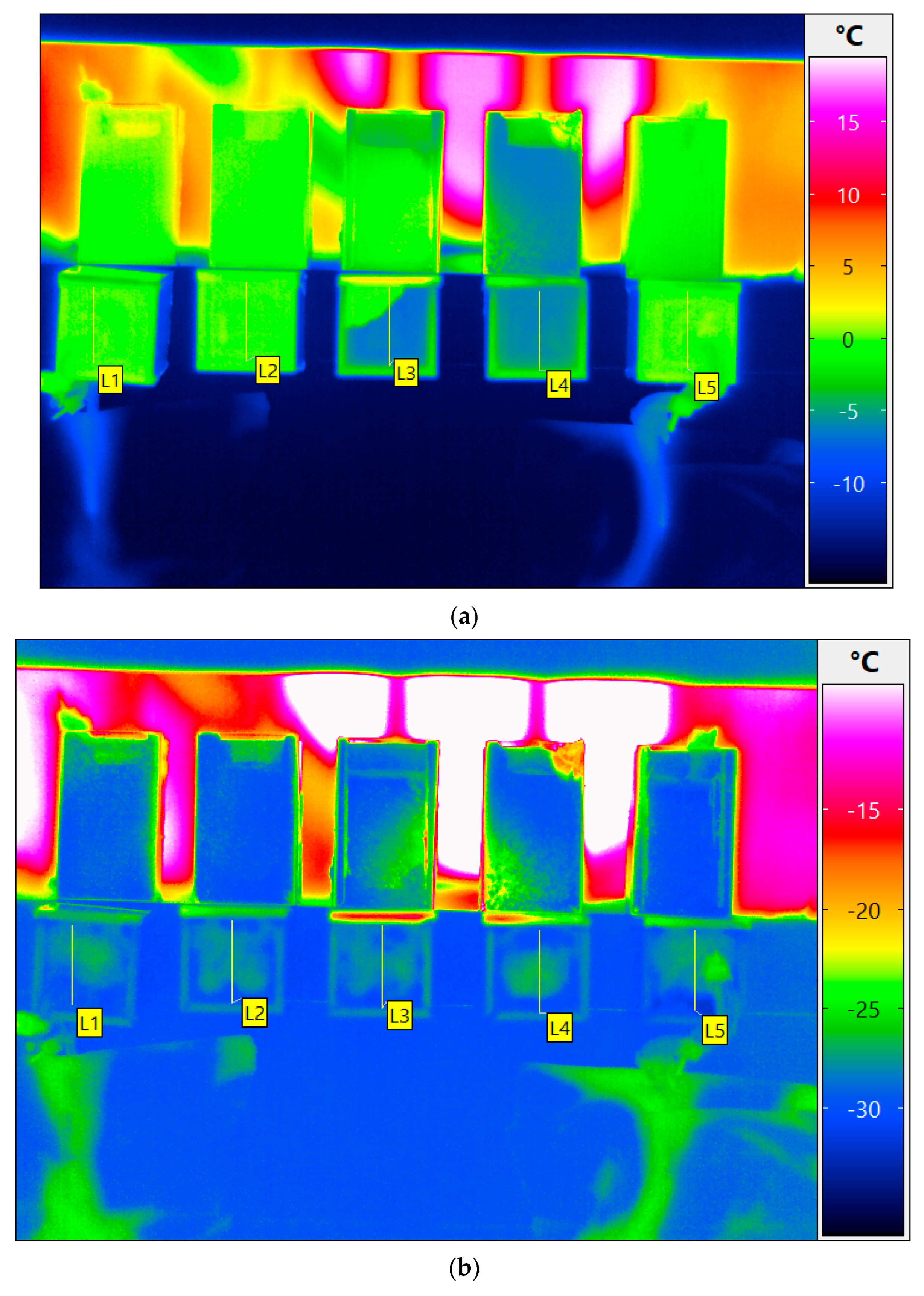
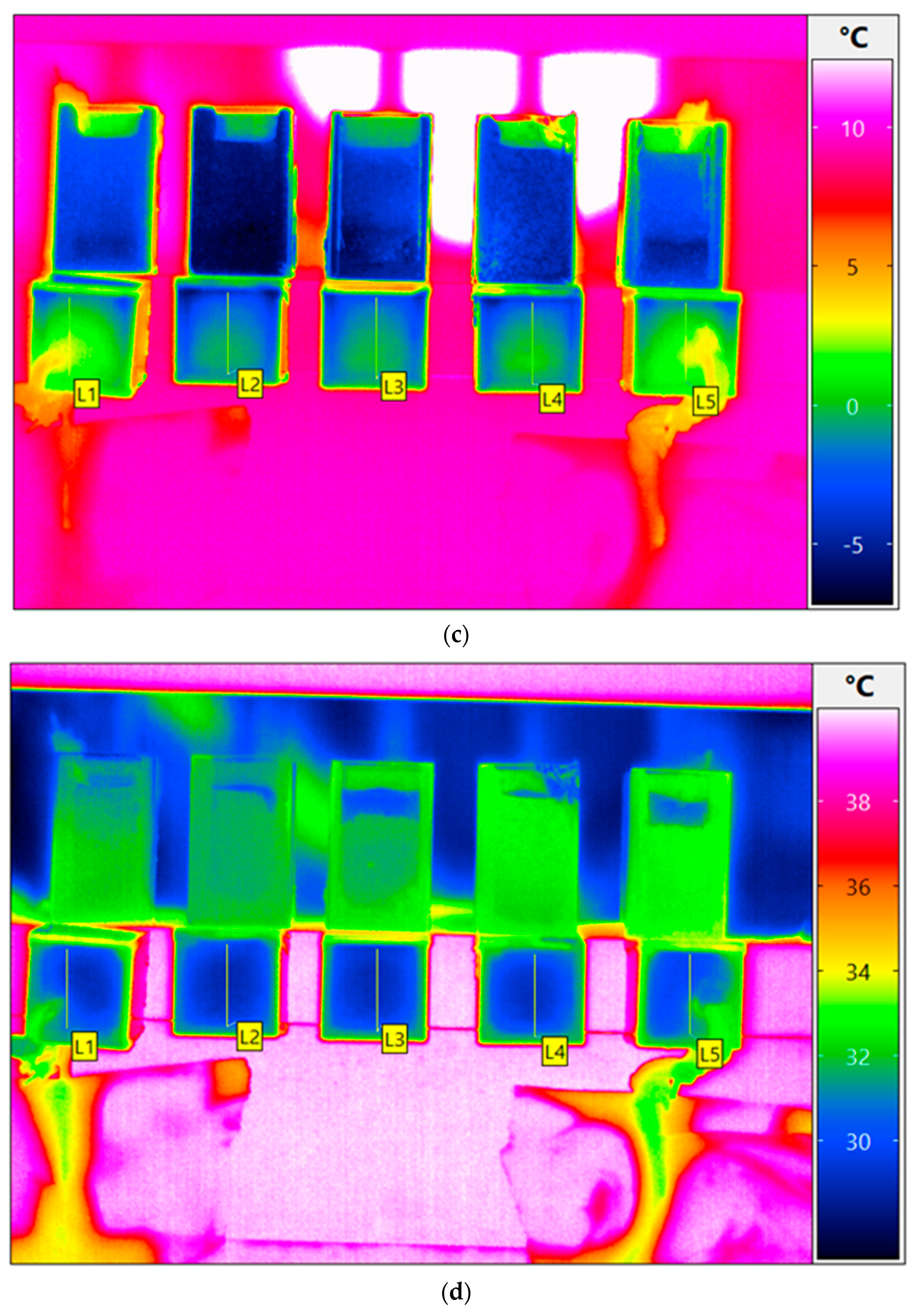
Figure 5.
(a) Thermogram of cuvettes 1 through 5 with profiles L1 to L5 at the surface after 116 min (1.93 h) at the time of nucleation and freezing. (b) Thermogram of cuvettes 1 through 5 with profiles L1 to L5 at the surface after 820 min (13.7 h) where only very small temperature differences prevail. The intense reflection in white is from metal surfaces inside the freeze-dryer. (c) Thermogram of cuvettes 1 through 5 with profiles L1 to L5 at the surface after 1685 min (28.1 h). Local temperature differences in the presence of probes are clearly visible. The intense reflection in white is from metal surfaces inside the freeze-dryer. (d) Thermogram of cuvettes 1 through 5 with profiles L1 to L5 at the surface after 2700 min (45 h) where only very small temperature differences prevail.
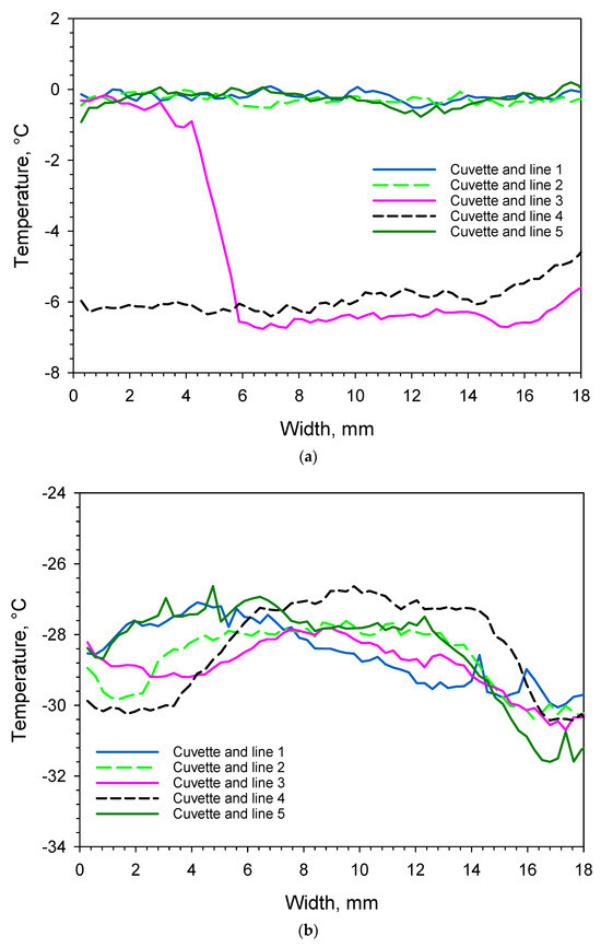
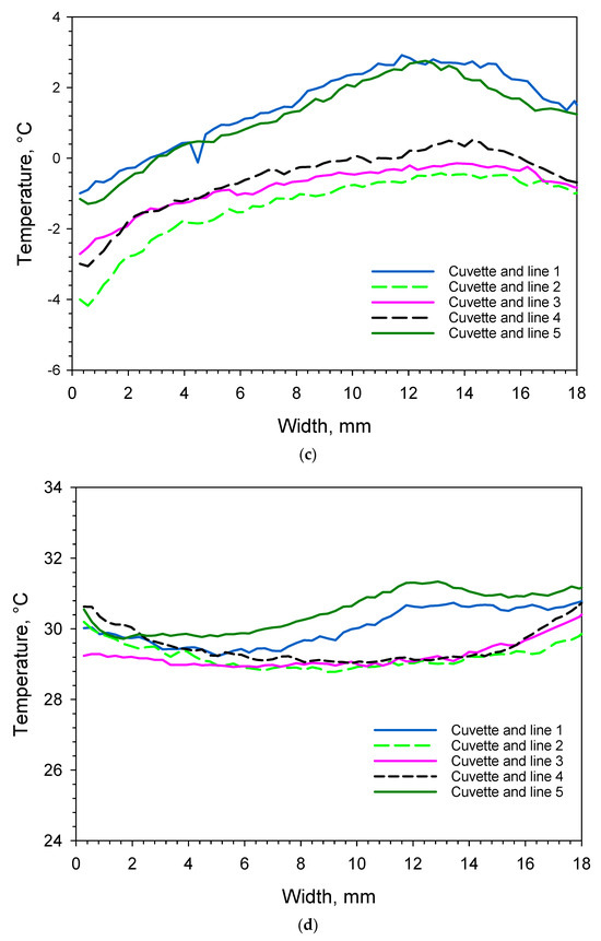
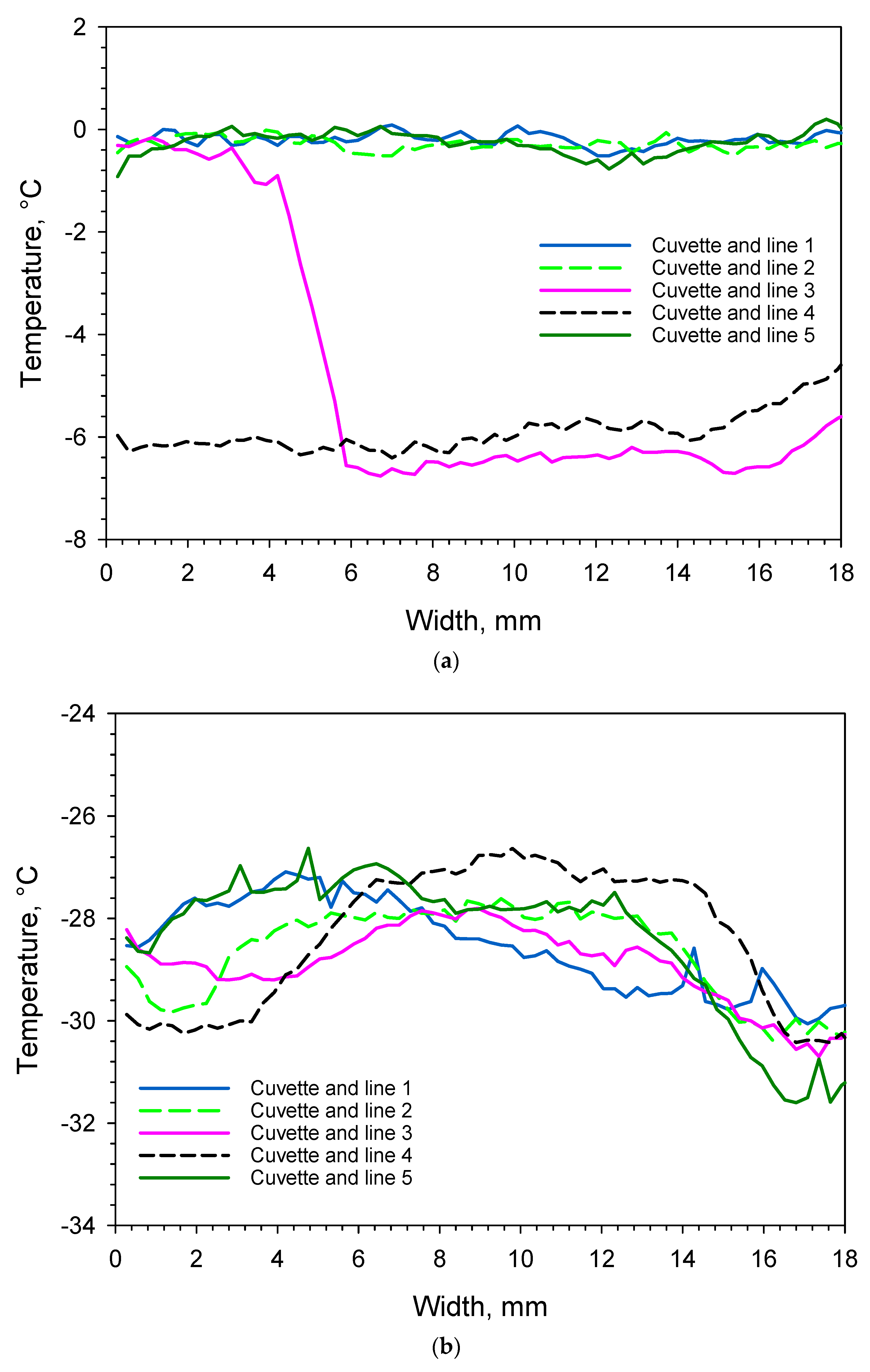
Figure 6.
(a) Temperature readout of lines 1–5 as a function of cuvette width after 116 min (1.93 h), see text for further explanations. (b) Temperature readout of lines 1–5 as a function of cuvette width after 820 min (13.7 h) with a rather uniform temperature of −29 °C. (c) Temperature readout of lines 1–5 as a function of cuvette width after 1685 min (28.1 h) with two different temperature ranges. The material with probes is about 2 °C and the material without probes is −1 °C. (d) Temperature readout of lines 1–5 as a function of cuvette width after 2700 min (45 h) with a rather uniform temperature of 30 °C.

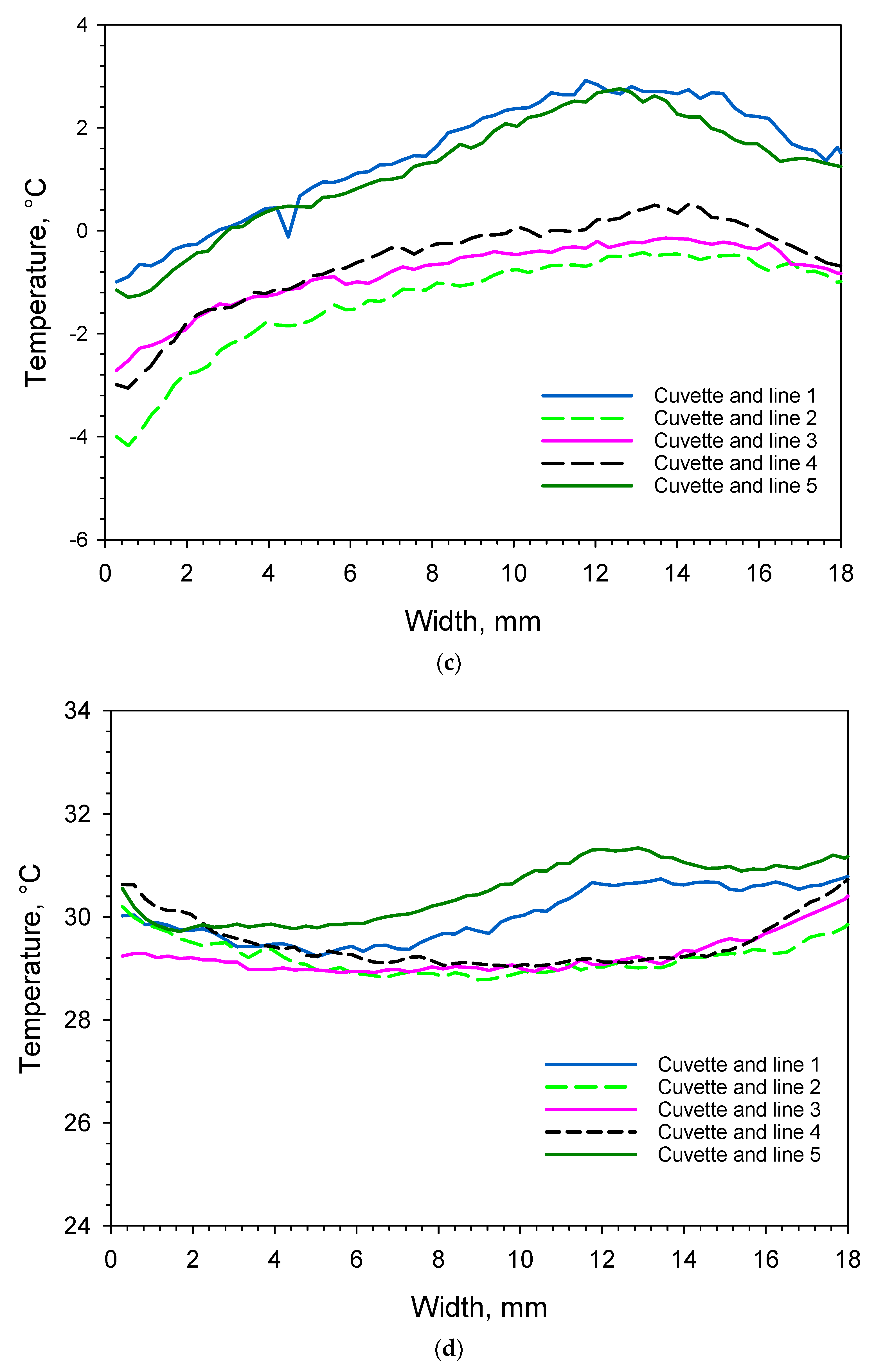
Figure 7.
Thermogram of cuvettes 1, 2 and 3 after 1685 min (28.1 h). The shelf is displayed in white because it had already reached 10 °C and is out of the colour-coded range for the temperature scale. The leftmost cuvette is equipped with a Pt100 probe.
3.1. Monitoring of A Freeze-Drying Cycle for a Mannitol/Sucrose Solution
3.1.1. Full Freeze Drying Cycle
Figure 2 shows the full freeze-drying cycle of the mannitol/sucrose solution. Supercooling and nucleation takes place around 2 h, and the material reaches 0 °C again, after which it ultimately freezes and then undergoes an annealing step. Thereafter, the primary drying and secondary drying steps take place. Figure 3 is complementary to Figure 2 and is based on machine readouts.
3.1.2. Supercooling and Freezing
As discussed by Geidobler et al., the freezing of water is a complex process, and it becomes even more complex when a pharmaceutical formulation undergoes freezing [17]. Liquids need to be cooled substantially below their equilibrium freezing temperature in order to spontaneously freeze through an initial primary nucleation that subsequently leads to the additional growth of ice-crystals [17]. In freeze-drying, uniform and simultaneous freezing behaviours and the size of the ice crystals are directly impacting the primary drying (rate) and ultimately the quality of the final product as comprehensively outlined by Juckers et al. [16]. Figure 4a shows that the mannitol/sucrose solution in cuvettes 1 and 5 (with probes present) froze first. The supercooled liquid in cuvettes 1 and 5 reached −3.5 and −5 °C, respectively, before freezing, as measured using the IR camera. The corresponding values obtained from the Pt100 probe and LyoRX probe were −5.1 and −7.0 °C, respectively. Table 1 contains a summary of data with respect to nucleation temperatures and order of freezing. When comparing Figure 4a and Figure S1, it can be seen that the surface was warmer for a longer period of time just after nucleation. Whether this can explain the observed difference between the probes and the IR camera readings is unclear. In fact, cuvette 4 contained supercooled liquid down to −11.5 °C before it froze, as measured at the surface using the IR camera. This observation is in line with Roy and Pikal’s work, which concluded that presence of probes increases ice-nucleation temperature [4]. At this point, the LyoRX (resistivity sensor) in cuvette 5 rapidly increases to about 95%, indicating solidification as shown in Figure 3. Figure 5a shows a specific case for cuvette 3, where the bottom right corner at the surface shows supercooled liquid in blue and the recently frozen formulation in the top left corner in light green. It should be noted that the actual nucleation and freezing take place within a few seconds. Fortunately, the IR camera captured this event in the 116th minute (1.93 h) of the freeze-drying program. In Figure 6a, the temperature profile along L3 is displayed, in which three IR pixels make up every mm on the x-axis. That profile shows both frozen and super-cooled liquid. All other cuvettes except for number 4, shown in Figure 5a, already contained frozen mannitol/sucrose at this stage. Cuvette 4 still contained supercooled liquid, which is in line with its actual time of freezing, which was approximately after 2.3 h as can be seen in Figure 4a.

Table 1.
Overview of water content in the final product, order of freezing and nucleation temperatures.
3.1.3. Sublimation/Primary Drying
The sublimation step started after the annealing step was completed by evacuating the freeze-drying chamber down to about 0.06 mbar, which then progressed for 23 h. Figure 4b shows that the sublimation rates were higher in cuvettes 1 and 5 (the slope is steeper 18–22 h into the program). This is in agreement with Roy and Pikal’s observations [4]. At the beginning of the sublimation phase after 13.7 h, it can be seen from Figure 5b and Figure 6b that the temperature at the surface of the cuvettes was rather uniform around −29 °C regardless if a probe was present or not. In contrast to that, after 28.1 h, it can be observed in Figure 5c and Figure 6c that there was a temperature difference of approximately 3.5 K at the surface in cuvettes 1 and 5 as compared with the cuvettes without probes. As mentioned before, care was taken not to measure the wires that connected the probes to the freeze-dryer. The thermal effect of the probe and the faster progress of primary drying can clearly be seen in Figure 7 as well. The leftmost cuvette (containing a Pt100 probe) was clearly ahead of the other two cuvettes also along the depth profile.
3.1.4. Secondary Drying
At the end of the sublimation phase, the pressure was reduced further and the secondary drying commenced after 34 h, lasting about 10 h. In Figure 5d and Figure 6d, it can be observed that the thermal effect due to the presence of probes is still visible, but it is much weaker. It is, however, noteworthy that the upper layer of the material during later stages of the secondary drying were cooler than the bottom due to the heating from the shelf. This was observed in earlier works as well [6], but those results lacked the higher resolution available in this study. The supplementary materials contain a figure that shows a graph of this evaporative cooling effect (Figure S6).
3.1.5. Residual Water Content in the Freeze-Dried Material
One replicate per cuvette was measured using the Karl Fischer titration. About 400 mg of solid mannitol/sucrose was available per each cuvette, which was initially filled with 8.5 mL of the 5% pharmaceutical formulation. The average residual water content in the material after drying was 5.85 ± 0.20% (m/m), ±1 SD for n = 5. The average water content in cuvettes 1 and 5 equipped with probes was 5.69 ± 0.17%, and in the remaining cuvettes 2, 3 and 4 without probes, it was 5.96 ± 0.18%. Whether the lower water content in cuvettes 1 and 5 is directly correlated to the presence of the probes (and the higher primary drying speed) is unsure, but there is at least an indication. Table 1 contains additional information about the water content per cuvette, the order of nucleation and the minimum temperatures of the supercooled pharmaceutical formulation just before nucleation and subsequent freezing.
4. Conclusions
In this study, we report that by using an appropriate lens and a higher resolution of the IR microbolometer, high-resolution thermograms of a pharmaceutical formulation undergoing a freeze-drying process were obtained. It was also confirmed that presence of probes in the material alters the freezing behaviour and the primary drying process (as already observed). However, by using the current setup, it was possible to quantify the thermal effect of the probes present in the material at different stages of the freeze-drying process. The temperature was around 3.5 K higher during primary drying in comparison with the vials without probes. All other (cuvettes) vials thus lagged in drying speed in comparison with the ones containing probes. Thus, the presence of probes generally overestimates the temperature prevailing during primary drying. The main sensors used for the monitoring of the freeze-drying processes are Pt100 probes and LyoRX probes. These probes are always in direct contact with the materials undergoing drying.
In this study, 8.5 mL of pharmaceutical formulation was freeze-dried. This is a rather large volume in comparison with large-scale operations in the pharmaceutical industry, which normally uses smaller vials filled with 1–2 mL of liquid. It is very likely that the thermal effect due to the presence of the probes would increase even further as the volume-ratio between probe and liquid increases. It would be worthwhile to repeat experiments with a lower fill-volume to confirm this assumption.
IR thermography provides superior spatial and thermal resolution that is also contact-free. To date, such studies have relied on special designs of freeze-dryers and sometimes even special vials equipped with Ge-windows (cuvettes) for full exploitation. IR cameras combined with freeze-dryers have therefore been limited to research applications. In large-scale freeze-drying, it would be impossible to use vials/cuvettes equipped with germanium windows. It would, be possible to quantify the temperature (contactless) and especially the time of freezing at the surface of the material in every single standard vial standing on each shelf. This could be realized if a small enough camera (per shelf) could be integrated with an adequate lens. Miniature versions of IR cameras could then be incorporated into new equipment relatively easily for monitoring surface temperatures even for routine applications. Such small IR cameras are commercially available and could possibly be installed on the underside of each shelf [19].
Supplementary Materials
The following supporting information can be downloaded at: https://www.mdpi.com/article/10.3390/app14073120/s1, Figure S1: Nucleation temperatures can be seen at the dip of each measurement area on the y-axis with respective time of nucleation on the x-axis. Measurements of average temperature at the top and bottom of each cuvette R6 to R15and R16 were used to generate the plot. Figure S2: Entire freeze-drying process; top and bottom view of cuvettes with and without probes using average temperature readouts from R6 to R15 and R16. Figure S3: Primary drying process, top and bottom view of cuvettes 1 to 5 with and without probes using average temperature readouts from R6 to R15 and R16. Figure S4: Selection showing primary drying process. Surface, top and bottom view of cuvettes 1 and 2 with and without a probe using average temperature readouts from R1, R2, R6, R7, R11, R12 and R16. Figure S5: Thermogram of cuvettes 1 to 5 with profiles L1 to L5 at the surface and L6 along the depth profile after 2700 min, 45 h. Figure S6: Temperature readout of lines 1–6 as a function of cuvette at the surface and depth (for line 6) after 2700 min (45 h). Video S1: The 2700 thermograms of the whole freeze-drying cycle have been converted into a film-clip covering 45 h from −40 ° C to 40 °C. The thermal effect of the probes can clearly be seen at the surface in the cuvette to the left and to the right especially when the shelf temperature reaches 0 °C and higher.
Author Contributions
Conceptualization, H.E.; Methodology, H.E. and J.C.-G.; Formal analysis, H.E.; Investigation, H.E. and J.C.-G.; Writing—original draft, H.E.; Writing—review & editing, H.E. and J.C.-G.; Supervision, H.E. All authors have read and agreed to the published version of the manuscript.
Funding
This research received no external funding.
Informed Consent Statement
Not applicable.
Data Availability Statement
The raw data supporting the conclusions of this article will be made available by the authors on request.
Acknowledgments
The authors gratefully acknowledge the comments and suggestions for improvement made by Alex Juckers, Martin Christ, Osterode, Germany.
Conflicts of Interest
The authors declare no conflict of interest.
Disclaim
The European Commission does not endorse any special brand or make of equipment.
References
- Ohtake, S.; Izutsu, K.; Lechuga Ballesteros, D. (Eds.) Drying Technologies for Biotechnology and Pharmaceutical Applications; Wiley-VCH: Weinheim, Germany, 2020; ISBN 9783527341122. [Google Scholar]
- Difranco, N. Lyophilization of Pharmaceuticals: An Overview. Lubrizol CDMO. 8 October 2019. Available online: https://lubrizolcdmo.com/blog/lyophilization-of-pharmaceuticals-an-overview/ (accessed on 29 February 2024).
- Available online: https://en.wikipedia.org/wiki/Resistance_thermometer#Pt (accessed on 29 February 2024).
- Roy, M.L.; Pikal, M.J. Process control in freeze-drying: Determination of the end point of sublimation drying by an electronic moisture sensor. J. Parenter. Sci. Technol. 1989, 43, 60–66. [Google Scholar]
- Emteborg, H.; Zeleny, R.; Charoud-Got, J.; Martos, G.; Lüddeke, J.; Schellin, H.; Teipel, K. Infrared Thermography for Monitoring of Freeze-Drying Processes: Instrumental Developments and Preliminary Results. J. Pharm. Sciences 2014, 103, 2088–2097. [Google Scholar] [CrossRef]
- Emteborg, H.; Charoud-Got, J.; Seghers, J. Infrared Thermography for Monitoring of Freeze Drying Processes—Part 2: Monitoring of Temperature on the Surface and Vertically in Cuvettes during Freeze Drying of a Pharmaceutical Formulation. Pharmaceutics 2022, 14, 1007. [Google Scholar] [CrossRef]
- Fissore, D.; Pisano, R.; Barres, A.A. Process analytical technology for monitoring pharmaceuticals freeze-drying–A comprehensive review. Dry. Technol. 2018, 36, 1839–1865. [Google Scholar] [CrossRef]
- Van Bockstal, P.J.; Corver, J.; De Meyer, L.; Vervaet, C.; De Beer, T. Thermal Imaging as a Noncontact Inline Process Analytical Tool for Product Temperature Monitoring during Continuous Freeze-Drying of Unit Doses. Anal. Chem. 2018, 90, 13591–13599. [Google Scholar] [CrossRef] [PubMed]
- Lietta, E.; Colucci, D.; Distefano, G.; Fissore, D. On the Use of Infrared Thermography for Monitoring a Vial Freeze-Drying Process. J. Pharm. Sci. 2019, 108, 391–398. [Google Scholar] [CrossRef] [PubMed]
- Colucci, D.; Prats-Montalbán, J.M.; Fissore, D.; Ferrer, A. Application of multivariate image analysis for on-line monitoring of a freeze-drying process for pharmaceutical products in vials. Chemom. Intell. Lab. Syst. 2019, 187, 19–27. [Google Scholar] [CrossRef]
- Colucci, D.; Maniaci, R.; Fissore, D. Monitoring of the freezing stage in a freeze-drying process using IR thermography. Int. J. Pharm. 2019, 566, 488–499. [Google Scholar] [CrossRef] [PubMed]
- Klijn, M.E.; Hubbuch, J. Application of ultraviolet, visible, and infrared light imaging in protein-based biopharmaceutical formulation characterization and development studies. Eur. J. Pharm. Biopharm. 2021, 165, 319–336. [Google Scholar] [CrossRef] [PubMed]
- Harguindeguy, M.; Stratta, L.; Fissore, D.; Pisano, R. Investigation of the freezing phenomenon in vials using an infrared camera. Pharmaceutics 2021, 13, 1664. [Google Scholar] [CrossRef] [PubMed]
- Vallan, A.; Fissore, D.; Pisano, R.; Barresi, A.A. On the Use of Temperature Measurements as a Process Analytical Technology (PAT) for the Monitoring of a Pharmaceutical Freeze-Drying Process. Pharmaceutics 2023, 15, 861. [Google Scholar] [CrossRef]
- Jiang, X.; Kazarin, P.; Sinanis, M.D.; Darwish, A.; Raghunathan, N.; Alexeenko, A.; Peroulis, D. A non-invasive multipoint product temperature measurement for pharmaceutical lyophilisation. Sci. Rep. 2022, 12, 12010. [Google Scholar] [CrossRef] [PubMed]
- Juckers, A.; Knerr, P.; Harms, F.; Strube, J. Effect of the Freezing Step on Primary Drying Experiments and Simulation of Lyophilization Processes. Processes 2023, 11, 1404. [Google Scholar] [CrossRef]
- Geidobler, R.; Winter, G. Controlled ice nucleation in the field of freeze-drying: Fundamentals and technology review. Eur. J. Pharm. Biopharm. 2013, 85, 214–222. [Google Scholar] [CrossRef]
- Hawe, A.; Friess, W. Impact of freezing procedure and annealing on the physico-chemical properties and the formation of mannitol hydrate in mannitol-sucrose-NaCl formulations. Eur. J. Pharm. Biopharm. 2006, 64, 316–325. [Google Scholar] [CrossRef]
- Available online: https://www.flir.eu/products/flir-one-pro/ (accessed on 29 February 2024).


Disclaimer/Publisher’s Note: The statements, opinions and data contained in all publications are solely those of the individual author(s) and contributor(s) and not of MDPI and/or the editor(s). MDPI and/or the editor(s) disclaim responsibility for any injury to people or property resulting from any ideas, methods, instructions or products referred to in the content. |
© 2024 by the authors. Licensee MDPI, Basel, Switzerland. This article is an open access article distributed under the terms and conditions of the Creative Commons Attribution (CC BY) license (https://creativecommons.org/licenses/by/4.0/).