Article

Double Unloading Gas Control Technology for Fracturing Soft Coal Seams in Overlying Key Strata

1
Lu’an Chemical Sijiazhuang Co., Ltd., Jinzhong 045300, China
2
School of Emergency Management and Safety Engineering, China University of Mining & Technology (Beijing), Beijing 100083, China
*
Author to whom correspondence should be addressed.
Appl. Sci. 2024, 14(8), 3202; https://doi.org/10.3390/app14083202
Submission received: 19 February 2024 / Revised: 29 March 2024 / Accepted: 5 April 2024 / Published: 11 April 2024
(This article belongs to the Special Issue Advanced Methodology and Analysis in Coal Mine Gas Control)

Abstract

:
Based on the ‘three highs and one low’ geological conditions of high gas pressure, high gas content, high ground stress, and low permeability in deep coal seams, this study proposes a dual method of hydraulic fracturing of key layers of overlying rock layers combined with pre-extraction of gas via large-diameter caving boreholes. The aim is to unload and dissipate the coal seam by fracturing the overlying key strata, allowing the stress and energy from the excavation working face to be transmitted and transferred to the deep coal seam. Additionally, large-diameter drilling effectively increases the effective drainage radius of the coal seam, resulting in a shorter extraction time. To validate this approach, a fracturing model and a gas extraction model were established for the key layers of the overlying rock layer using the engineering background of the 15,111 excavation working face of a mine in Shanxi. FLAC3D software v.6.0 was utilized to simulate the stress and energy changes of the coal seam before and after fracturing of the key layers, while COMSOL software v.6.0 was used to analyze the gas migration conditions, permeability, and effective drainage radius changes before and after drilling and caving drilling. The findings, combined with the engineering test results, conclude that key strata fracturing combined with large-diameter caving can effectively increase the permeability of coal seams and improve gas extraction. This study serves as a theoretical basis for guiding the design of gas drainage technology under the effects of coal seam pressure relief and permeability enhancement.

1. Introduction

About 50% of mines in China are classified as high gas or coal and gas outburst mines, with soft and low-permeability coal seams accounting for as much as 82% of these mines [1,2]. As mining operations go deeper, the in situ stress, gas content, and gas pressure gradually increase, while the permeability further decreases. The permeability of most outburst mines is only 1 × 10⁻⁴ to 1 × 10⁻³ md [3,4,5]. The poor gas permeability of coal seams makes it challenging to pre-extract gas, resulting in a high amount of residual gas. During the mining process, frequent abnormal gas outflow leads to the gas concentration in the working surface exceeding the limit, posing an increasingly serious threat of gas disasters [6,7,8]. Conventional drilling has limited effectiveness in dealing with this type of coal seam, as it has a small extraction radius, low drainage efficiency, and poor pressure relief effect on the original coal seam, making gas drainage more difficult [9,10]. Therefore, the main approach for gas control is to utilize external force measures to release surrounding rock stress, modify coal seam gas migration characteristics, and enhance drainage efficiency [11,12,13].
At present, various technologies are used to address high gas and low permeability coal seams, including mining protective layers [14,15], hydraulic slotting [16,17], hydraulic fracturing [18,19,20,21], hydraulic punching [22,23], and intensive gas drainage drilling [24]. Protective layer mining is currently the most effective method to prevent coal and gas outbursts, which has been successful in field practice [15,25]. Ni et al. [26] conducted industrial experiments on pulse hydraulic fracturing in both structural and non-structural zones, analyzing the extension direction of coal seam cracks during the pulse hydraulic fracturing process. Li et al. [27] conducted experiments using large-diameter boreholes in soft coal seams in geological structures, reducing the risks of collapse and coal and gas outbursts. However, conventional pressure relief, permeability enhancement, and drainage methods face new challenges in deep coal seam gas control. Mining protective layers requires favorable geological conditions and may not be feasible when the adjacent protective layer is too thin or the distance between coal seams is inappropriate. Additionally, cracks formed via hydraulic measures have limitations, as they have a short maintenance time and can be re-compacted under high stress conditions [28,29,30]. The ‘soft coal’ undergoes plastic deformation internally when subjected to high-pressure water, resulting in blocked cracks and reduced gas permeability [31]. In the soft coal seam, ordinary extraction drill holes are prone to problems such as jamming and plugging during the construction process, making gas extraction more difficult. This is mainly due to the large ground stress in the deep soft coal seam [32], and the current technology and process methods cannot realize effective pressure relief on the soft coal seam continuously, and it is difficult to fundamentally prevent the occurrence of coal and gas protrusion accidents. In addition, the above-mentioned technologies also have environmental impacts. During hydraulic fracturing, a certain amount of fracturing fluid is used and, when it enters underground drinking water sources through rock fractures, it may pose a threat to human health [33].
This paper aims to address the above issues by adopting a method that combines hydraulic fracturing in the overlying key layer with large-diameter borehole in the coal seam for comprehensive penetration enhancement management. The study involves hydraulic fracturing and decompression in the overlying key strata while simultaneously conducting large-diameter borehole drilling within the coal seam. An analysis is conducted on stress transfer and energy dissipation pertaining to pre- and post-fracturing unloading of the coal seam, and we study the change rules in permeability, gas pressure, and the effective extraction radius of the coal seam under double decompression conditions. The findings of this study will provide a theoretical basis for improving gas extraction and preventing coal and gas outbursts in soft coal seams.

2. Method

2.1. Theory

The research indicates that the overlying rock layer of the coal seam is a composite rock mass consisting of multiple layers. The transmission of stress in this layer primarily originates from the main/inferior key strata of the overlying rock. The key strata is a hard rock layer that can control the collapse activity of the overlying rock strata on the mining face partially or completely [34], and it is the most important path for the downward transmission of geostress to the coal seam [35]. The “weak layer” area in the coal seam excavation will form a high concentration of vertical stress and, at the same time, it is characterized by high gas pressure, low permeability of the coal seam, and a large gas pressure gradient. Based on these characteristics, a dual pressure relief gas control technology is proposed, involving hydraulic fracturing of the key strata overlying the coal seam (primary pressure relief of the coal seam) and large-diameter hole drilling (secondary pressure relief of the coal seam), as shown in Figure 1. The main key strata and inferior kay strata are determined based on the properties of the overlying rock and theoretical calculations. Hydraulic fracturing technology is used to fracture and relieve pressure on the rock mass overlying the key layers of the coal seam, thereby alleviating the pressure on the coal seam. Simultaneously, large-diameter hole drilling is employed in the coal seam to increase the diameter of the borehole, which provides the secondary decompression for the coal seam, causing the coal body to expand and enhancing its permeability. This approach significantly improves the gas drainage effect in the coal seam and provides theoretical support for the study of permeability in soft coal seams under pressure-relief conditions.

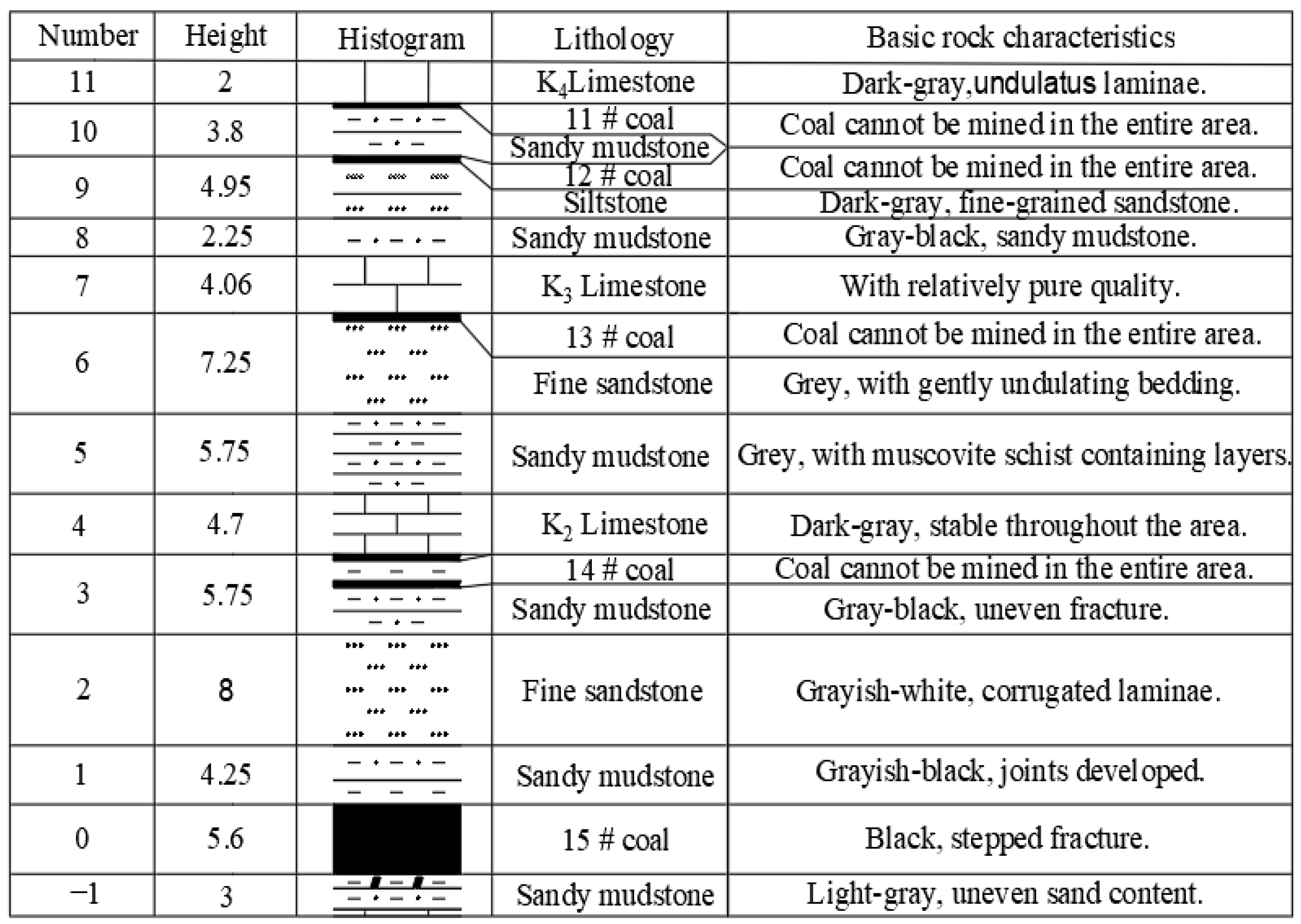
2.2. Coal Seam General Situation and Model Parameters

The 15,111 working face of a mine in Shanxi is located in the central disc area and its comprehensive geological histogram is shown in Figure 2. The working face has an elevation range of 557–613 m and is designed to be mined with a strike length of 3529 m and an inclined length of 161 m–322 m. It has a recoverable reserve of 6,466,700 t. The 15,111 working face is a coal and gas outburst working face and, in order to carry out production, it must meet the requirement of eliminating the danger of gas proliferation as stated in the relevant laws and regulations. The original coal seam has a gas content of 11.22 m3/t, which needs to be reduced to less than 8 m3/t to eliminate the danger of gas proliferation. Therefore, the target pre-pumping rate of the 15,111 working face is set at 30%. However, due to the lack of systematic research, the previous gas management work relied on field experience to formulate the extraction program, resulting in unstable extraction results with an extraction rate of less than 30% and difficulty in meeting the standard. The physical and mechanical parameters of the rock layer measured through tests are presented in Table 1, while the gas-related parameters of the coal seam are shown in Table 2.

2.3. Hydraulic Fracturing Radius Determination

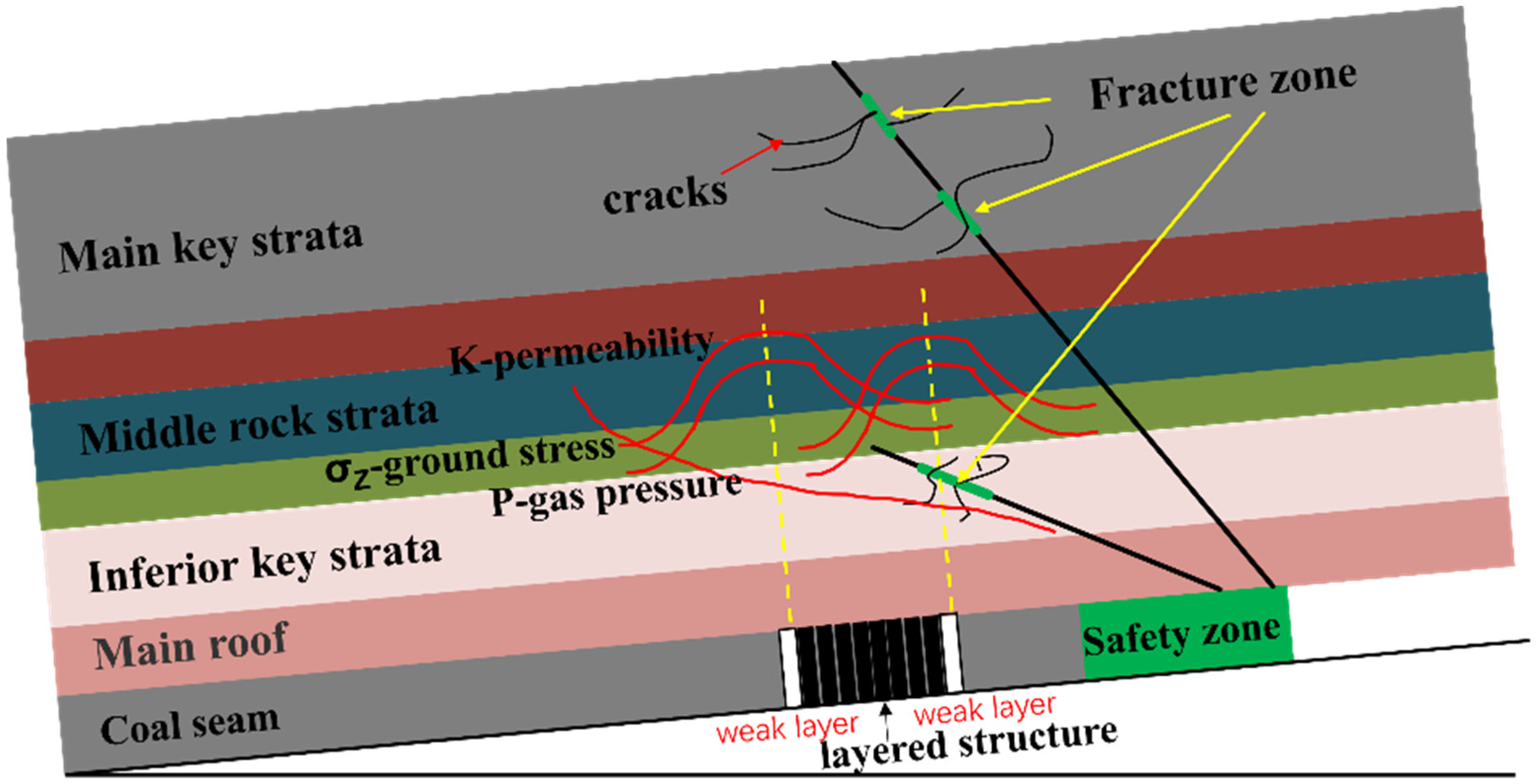
2.3.1. Determination of Key Strata of Overlying Rock Strata

  • Determine hard rock stratum according to load
According to masonry beam theory, the nth layer of the overlying rock layer bears the load (qm) of the nth layer to the mth layer (qm)n:
( q m ) n = E n h n 3 i = n m γ i h i i = n m E i h i 3 .
In Formula (1), Ei represents the elastic modulus of the ith layer of the rock layer, GPa; γi is the unit weight of the ith layer, kg/m3; and hi is the thickness of layer i, m.
If layer m + 1 is a hard rock layer, it should have the following supporting characteristics:
( q m ) n > ( q m + 1 ) n .
According to Equation (2), the load (q1) of the first layer itself is 106.3 kPa, while the load (q2)1 from the first layer to the second layer is 31.7 kPa. Based on Equation (2), it can be inferred that the second layer of overburden rock does not contribute to the loading of the first layer and can be considered as a hard rock stratum.
The load (q2) applied to the second layer itself is 208 kPa, the load (q3)2 applied to the second layer up to the third layer is 275.1 kPa, the load (q4)2 applied to the second layer up to the fourth layer is 281.4 kPa, the load (q5)2 applied to the second layer up to the fifth layer is 314.7 kPa, and the load (q6) applied to the second layer up to the sixth layer is 297.8 kPa. It can be seen that the sixth layer is a hard rock layer, and the load on the second layer is 314.7 kPa, which controls the upper three layers.
Similarly, (q6) = 188.5 kPa, (q7)6 = 217.6 kPa, (q8)6 = 255 kPa, (q9)6 = 261.4 kPa, (q10)6 = 296 kPa, (q11)6 = 316.1 kPa, and (q12)6 = 290.1 kPa; therefore, the twelfth layer is a hard rock layer, and the load that had been applied to the sixth layer is 316.1 kPa, controlling the upper five layers.
Therefore, according to the theory related to the key strata [36], the second, sixth, and twelfth layers of the upper part of the coal seam were determined to be hard rock layers.
2.
Calculate the breaking distance of the hard rock stratum
Assuming that the initial breaking distance of layer i is (La)i and the periodic breaking distance of layer i is (Lb)i, the calculation formula is as follow:
( L a ) i = h i × 2 R i q i ,
( L b ) i = h i × R i 3 q i
where hi is the height of the ith layer, m; Ri is the tensile strength of the ith layer, MPa; and qi is the load of the ith layer of hard rock bearing its control rock layer, MPa.
Based on the formula, it can be inferred that (Lb)i = (La)i/2.45. The initial breakage distances of the second and sixth layers are determined as 78.5 m and 74.7 m, respectively, while the periodic breakage distances are measured at 32.1 m and 30.5 m, correspondingly.
3.
Determine the key strata according to the breaking distance
The initial and periodic breakage distances of the second and sixth layers in the overlying hard rock strata were calculated using Equations (3) and (4), respectively. Based on the calculation results, it is evident that the magnitude of the initial breakage distance for the hard rock layer follows this order: (La)2 > (La)6; similarly, periodic breakage distance: (Lb)2 > (Lb)6. Consequently, we can conclude that the second layer of hard rock acts as a primary key strata with synchronous failure occurring in both layers. Therefore, considering the overburdened rock strata, it is essential to recognize the second layer as the main key strata while regarding the sixth layer as the inferior one.

2.3.2. Determination of Crack Initiation Pressure

Based on the theory of linear elastic tensile damage, the H-W model was employed to calculate the rupture pressure. The model assumes the following: (1) the rock is impermeable; (2) the rupture takes place in the borehole wall; and (3) the rock experiences tensile damage. According to this criterion, the rupture equation is derived without considering the pore pressure of the top sandstone:
p b = 3 σ h σ H + σ t
where Pb is the rock initiation pressure, σh is the minimum horizontal stress, σH is the maximum horizontal stress, and σt is the tensile strength of rock.
According to the field measurement and test results, the minimum horizontal stress σh = 8.08 MPa, the maximum horizontal stress σH = 14.98 MPa, and the tensile strength σt = 10 MPa of the rock mass in the key strata can be calculated to obtain the crack initiation pressure Pb of the rock mass in the key strata—19.26 MPa.

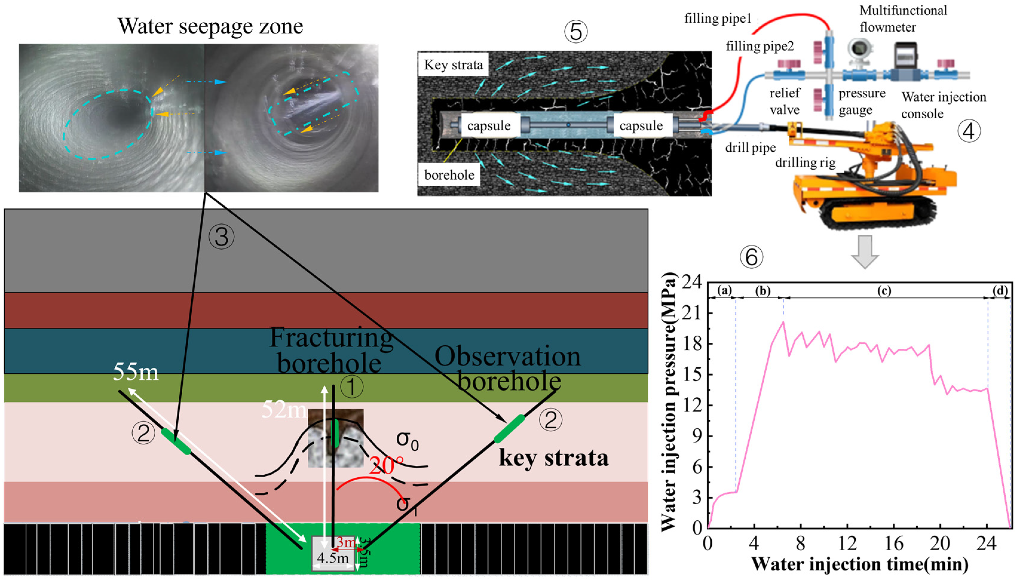
2.3.3. Determination of Fracturing Radius

As shown in Figure 3, different colors are used to indicate different rock layers, the roadway section is 4.5 m wide and 3.5 m high. The fracturing test borehole, labeled as ➀, is located in the roadway gang and has a height of 1.5 m. It has an azimuth angle of 0° (angle with the center line of the roadway), an inclination angle of 12°, and a depth of 52 m. The observation borehole, labeled as ➁, is positioned 3 m horizontally from the fracturing borehole. It has a height of 1.5 m, an azimuth angle of 20°, an inclination angle of 12°, and a depth of 55 m. The water seepage zone of the observation borehole after fracturing is labeled as ➂. ➃ shows a diagram of a hydraulic fracturing unit. The maximum pumping pressure of the emulsion pump is 30 MPa, which fulfills the requirement for the fracturing pressure of the key layer of the top plate. To achieve automatic water pressure sealing and maintain the water injection pressure, the MA ZF-A64-enhanced ME rubber water injection sealing device shown in Figure ➄ was used, with a length of 2 m and a maximum expansion diameter of 120 mm. ➅ shows a graph of the change in pressure in the pressure gauge with time during the fracturing process. The on-site water injection process is divided into four stages, as shown in Figure 3: (a) the water pressure naturally rises and reaches equilibrium at approximately 3.5 MPa; (b) the water injection pressure of the pump is manually increased to 20.15 MPa; (c) the water injection pressure is maintained at around 18 MPa until the pressure plummets to ensure continuous water injection and sufficient extension of rock cracks; (d) the water level in the hole is observed, and the pressure is manually released to switch off the injection pump. The comprehensive analysis of water injection pressure, water injection time, location of fracturing section, and water seepage section indicates that the sandstone fracturing pressure is 20.15 MPa, the sandstone holding pressure stage requires continuous water injection for 17.5 min, and the hydraulic fracturing radius is 15 m.

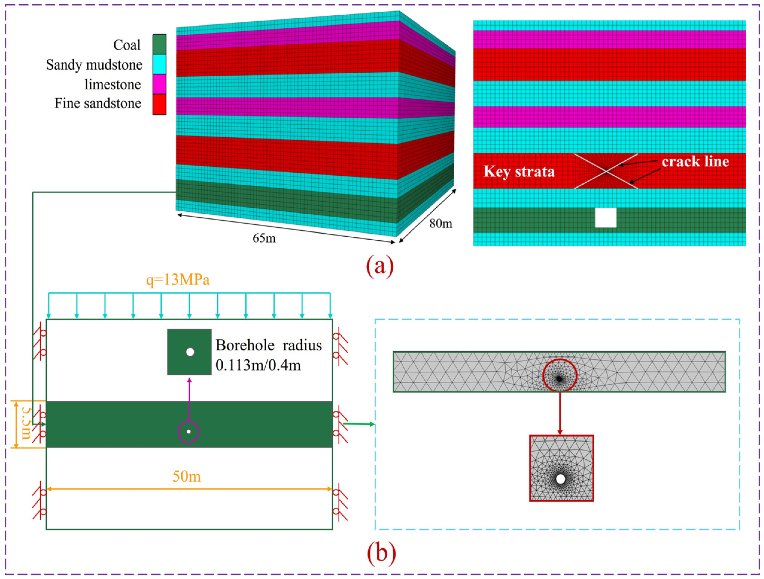
2.4. Establishing Numerical Models

2.4.1. Mathematical Modeling

  • Seepage equations of motion
The gas in the coal is mainly composed of two parts: free gas Q b and adsorbed gas Q a . Therefore, the total gas storage capacity is
Q = Q α + Q b = φ p M c R T + a b p 1 + b p 100 A M 100 + 31 M ρ s ρ a
where φ is the porosity of coal,%; p is the coal seam gas pressure, MPa; R is the gas molar constant, J/(mol·K); T is the coal seam temperature, K; Mc is the molar mass of methane, kg/mol; a is the maximum adsorbed gas amount of coal, m3/t; b is the adsorption constant, MPa−1; M is the proportion of coal moisture, %; A is the proportion of coal ash content,%; ρ s is the coal density, kg/m3; and ρ a is the gas density under standard conditions, kg/m3.
The gas flow in coal seam conforms to Darcy’s law of seepage, and the calculation equation is
V = k 0 μ p
where V is the gas seepage velocity, m/s; k0 is the initial permeability of the coal seam, and m2; μ is the gas dynamic viscosity coefficient, Pa s.
The flow of gas in coal seams conforms to the law of conservation of mass, and the calculation equation [37]:
Q t + ( ρ V ) = 0 .
Combine Equations (6)–(8) to obtain the following formula:
( φ p M c R T + a b p 1 + b p 100 A M 100 + 31 M ρ s ρ a ) t + ( p M c R T ) ( k 0 μ p ) = 0 .
2.
Control equation for coal deformation
Assuming that the coal seam is isotropic and considering the adsorption expansion effect, combined with Terzaghi’s effective stress formula and constitutive equation, the deformation control equation of the coal body can be obtained [38]:
G ( 1 2 v ) u j , i j + G u i , j j + ( a + 2 G 3 K s ) p , i + F i { [ 4 G 9 V m K s 2 ( 1 2 v ) 3 V m ] a b ρ s R T 1 + b p } p , i = 0
where G is the shear modulus, MPa; u i is the displacement of the coal body in the i direction, m; u i , j j , u j , i j is the displacement component; F i is the body stress, MPa/m3; p , i is the gas pressure in all directions, MPa; υ is Poisson’s ratio of coal body; Vm is the molar volume of methane under standard conditions, L/mol; and Ks is the volume modulus of the coal skeleton.
3.
Other equations
The dynamic model of coal seam porosity can be expressed as [39]
φ = φ 0 + ε ν 1 + ε ν
where φ 0 is the initial porosity of the coal seam, %; ε v is the volumetric strain of the coal seam.
k = k 0 1 + ε v ( 1 + ε v φ 0 ) 3
where k0 is the initial permeability of the coal seam.

2.4.2. Establishing Physical Models

Based on the FLAC3D software (http://www.itascacg.com/software/FLAC3D (accessed on 23 December 2023)), the study utilized a three-dimensional overburden rock fracturing model with 10 layers of different lithologies, as shown in Figure 4a. The model had dimensions of 80 × 65 × 50.4 (m) and the cutting face had dimensions of 3.5 × 4.5 (m). The specific physico-mechanical parameters of the rock layers can be found in Table 1. The initial ground stress field was established by applying a vertical stress of 13 MPa and a horizontal stress of 14.5 MPa based on on-site field measurements. A grid model was used to simulate the advancement of the working face, with the roadway being excavated for a distance of 10~70 m. Instead of hydraulic fracture cracks, crack lines were used, with a long crack of 30 m located between 40~70 m. The crack had a width of 15 m and a crack gap width of 0.2 m. This simulated the stress and energy distribution of the coal bed after the destruction of the key strata.
Based on the COMSOL software (http://cn.comsol.com/ (accessed on 2 January 2024)), the geometric model of gas extraction was established, as shown in Figure 4b. The length of the coal wall section is 50 m, and the thickness of the coal body is 5.5 m. The opening height of the extraction hole is 1.8 m, with a diameter of 113 mm for the ordinary drilling and 0.4 m for the hole making drilling. The bottom of the numerical model is a fixed boundary, while the boundaries of the left and right flanks are sliding boundaries. The top of the model represents the boundary of the constant load, with an overlying load of 13 MPa. Once the geometric model is generated, the model is then meshed.

3. Analysis of Simulation Results

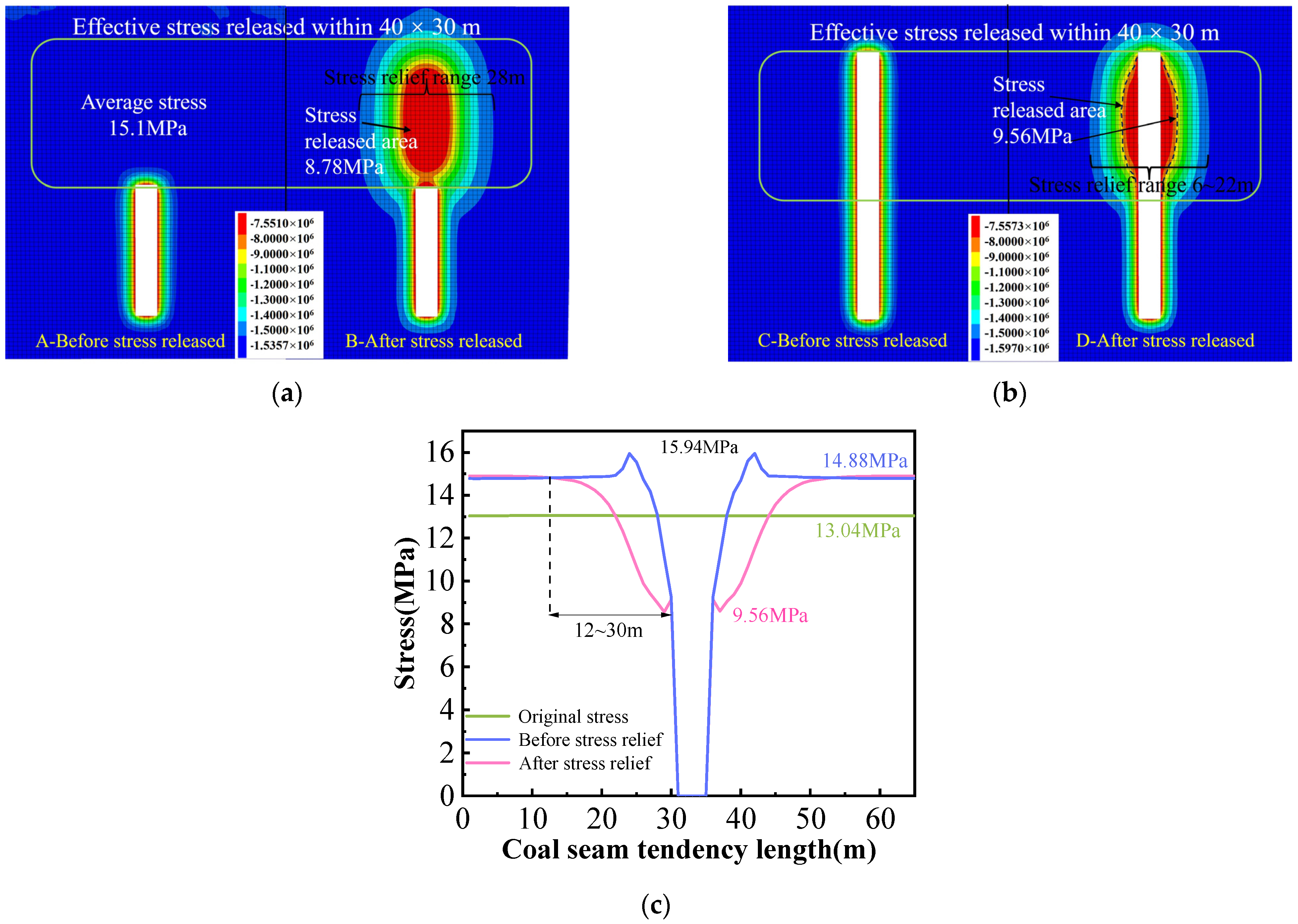
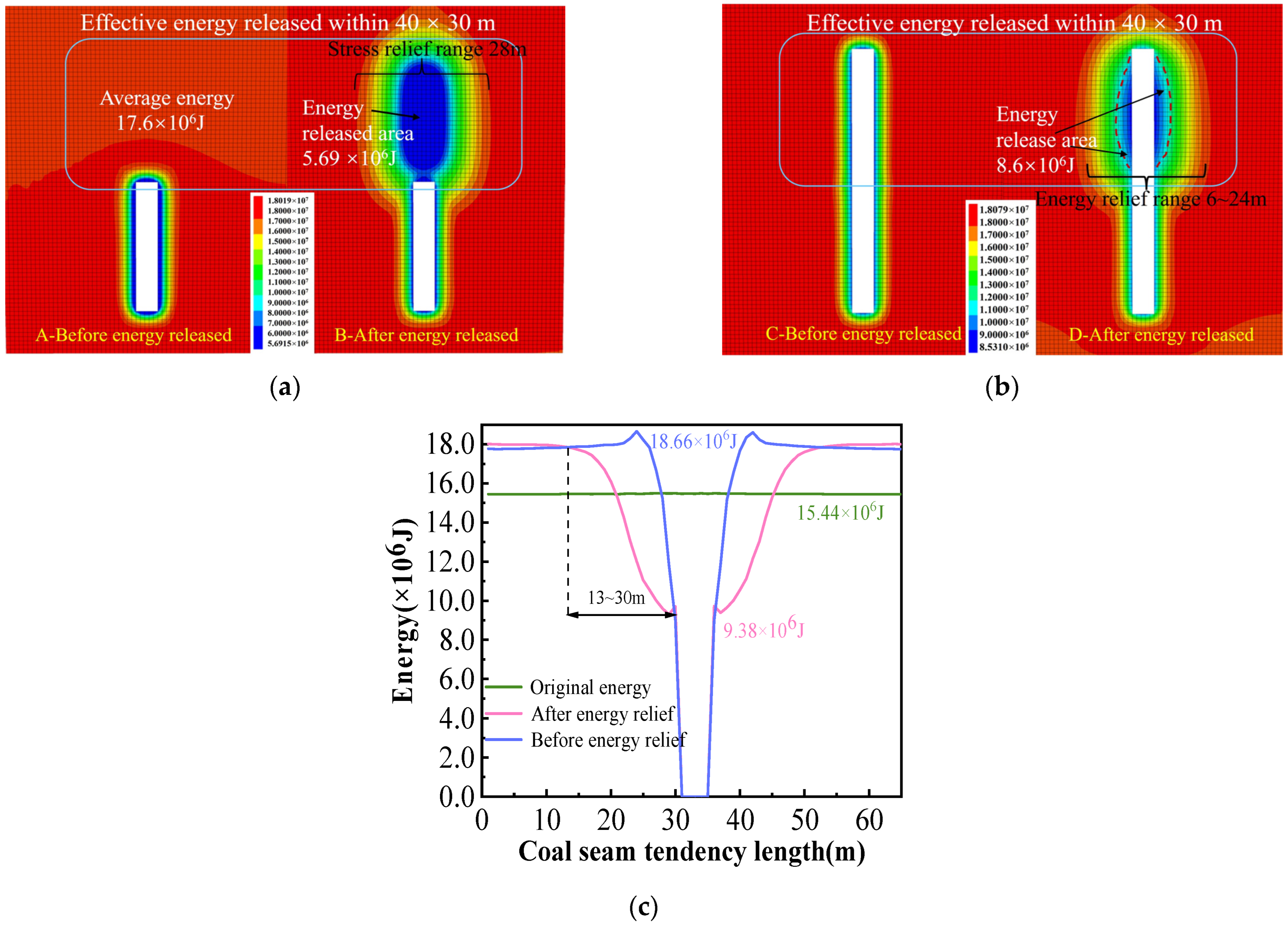
3.1. Coal Seam Stress–Energy Change Rule before and after Key Strata Stress Removal

Under the influence of ground stress and mining disturbance, the stress field and energy field of the coal seam are disrupted. This disruption results in the formation of three distinct areas: the broken pressure relief area, the stress concentration area, and the original stress area. In the broken pressure relief area, the vertical stress on the coal body is lower than the original stress, leading to the creation of more fissure channels and a reduction in stress concentration caused by the mining disturbance. The stress concentration area experiences an initial increase and then decrease in vertical stress on the coal body, causing compaction of pores and fissures and a decrease in permeability. This area is also prone to impact dynamics phenomena under the influence of the mining disturbance. The original stress area, on the other hand, is less affected by mining activities, resulting in a lower stress field for both the key layer and the coal seam. Here, the coal seam retains its complete layer structure, and the stress load is evenly transmitted downwards.

3.1.1. Coal Seam Stress Change Rule

When the excavation face reaches a depth of 40 m, hydraulic fracturing is carried out to decompress the overlying key strata. Figure 5a,b illustrates the stress cloud map before and after the coal seam is excavated to a depth of 70 m. After fracturing the overlying key strata, a distinct pressure relief area forms within the coal seam, spanning a range of 40 × 30 m. In Figure 5a, the depressurization of the key layer results in the formation of a stress relief zone extending up to 28 m in front of the excavation face, with the maximum reduction in stress being 6.32 MPa. In Figure 5b, when mining continues in the coal seam after relieving the key strata, the phenomenon of stress concentration on both sides of the roadway disappears, and the range of coal seam unloading is between 6–22 m.
The variation in stress in the coal seam at y = 56 m in Figure 5b is studied and presented in Figure 5c. From the figure, it is evident that the initial stress value of the coal seam is 13.04 MPa when unaffected by mining disturbance and pressure unloading. However, when mining is conducted without pressure unloading, there is a concentration of stress in the two gangs of the roadway, with the maximum value reaching 15.94 MPa. After pressure unloading of the key layer, the minimum stress value in the roadway gang within the coal seam is 9.56 MPa, with the maximum unloading stress being 7.4 MPa. This unloading accounts for 46% and has an average value of 3 MPa. The unloading range is observed to be between 12–30 m, which is consistent with the radius of hydraulic fracturing.

3.1.2. Coal Seam Energy Change Rule

The change rule of coal seam energy is similar to the change rule of coal seam stress. Key strata fracturing causes the redistribution of coal seam energy. The energy distribution cloud diagram of the coal seam is shown in Figure 6a,b. From Figure 6a, it can be observed that there is an energy peak area at 3~4 m in front of the roadway after the coal seam is excavated along the tendency to 40 m. After fracturing the key strata, the energy is redistributed, resulting in an energy dissipation zone of about 40 × 30 m in front of the excavation working face. Figure 6b shows the coal seam after key layer decompression. The energy concentration phenomenon disappeared in the two gangs of the roadway, and an energy dissipation zone formed within 3 m of the two gangs of the roadway. The energy dissipation range of the coal seam was 6~24 m.
The variation in energy in the coal seam at y = 56 m in Figure 6b is studied and presented in Figure 6c. Initially, the coal seam has an energy value of 15.44 × 10⁶ J when it is not affected by mining disturbance and pressure unloading. However, when mining without pressure unloading occurs, the peak energy value of the two gangs of the roadway increases to 18.66 × 10⁶ J. This indicates that the energy is transferred to the two gangs of the roadway after mining the coal seam, resulting in an energy concentration area and potential power phenomena. Furthermore, the peak energy at 3 m of the two gangs of the roadway decreases by more than 40% after the key strata is unpressurized, with a maximum energy dissipation of 9.28 × 10⁶ J. The unilateral energy dissipation range extends up to 17 m, which is consistent with the radius of hydraulic fracturing.

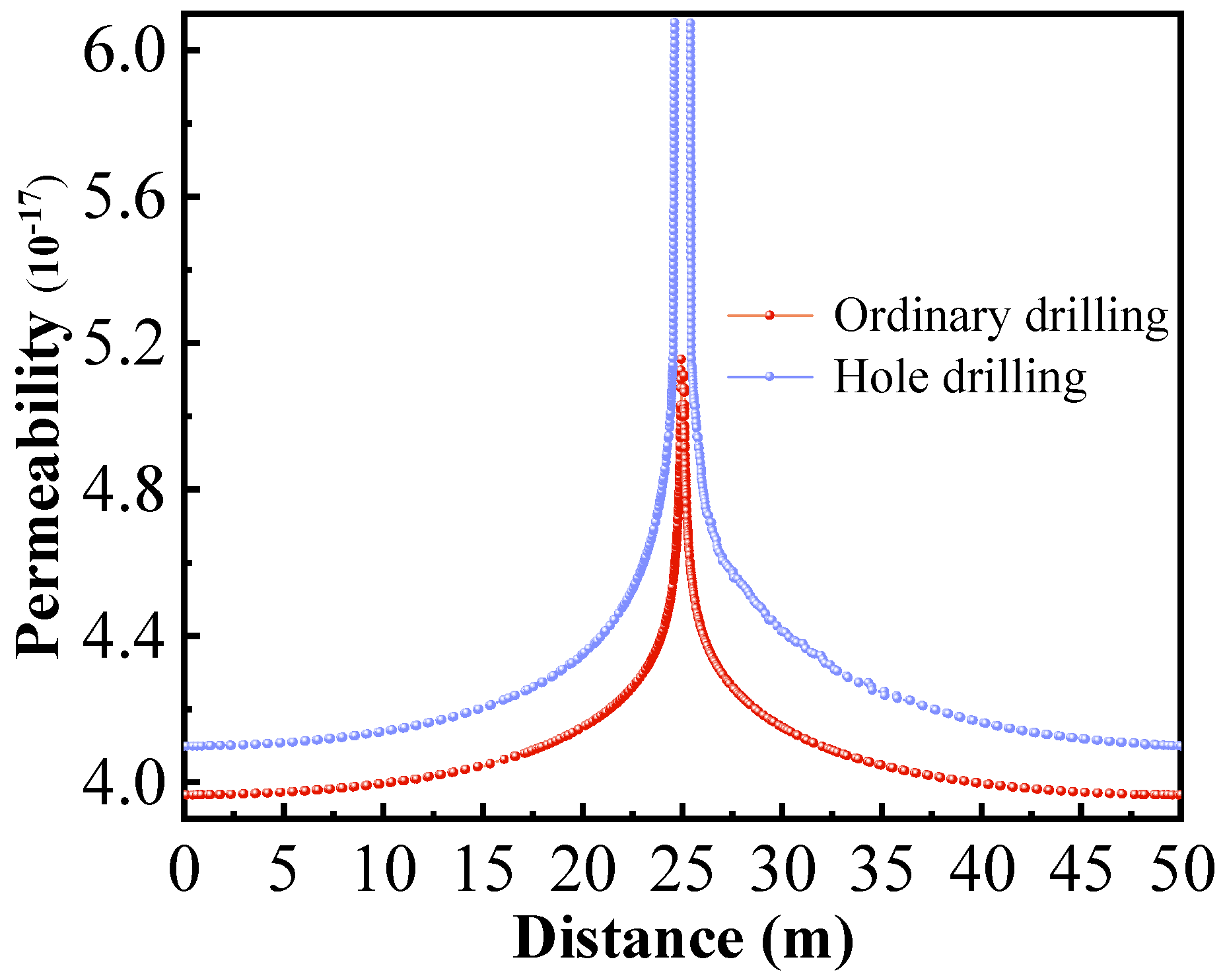
3.2. Coal Seam Permeability Change Rule

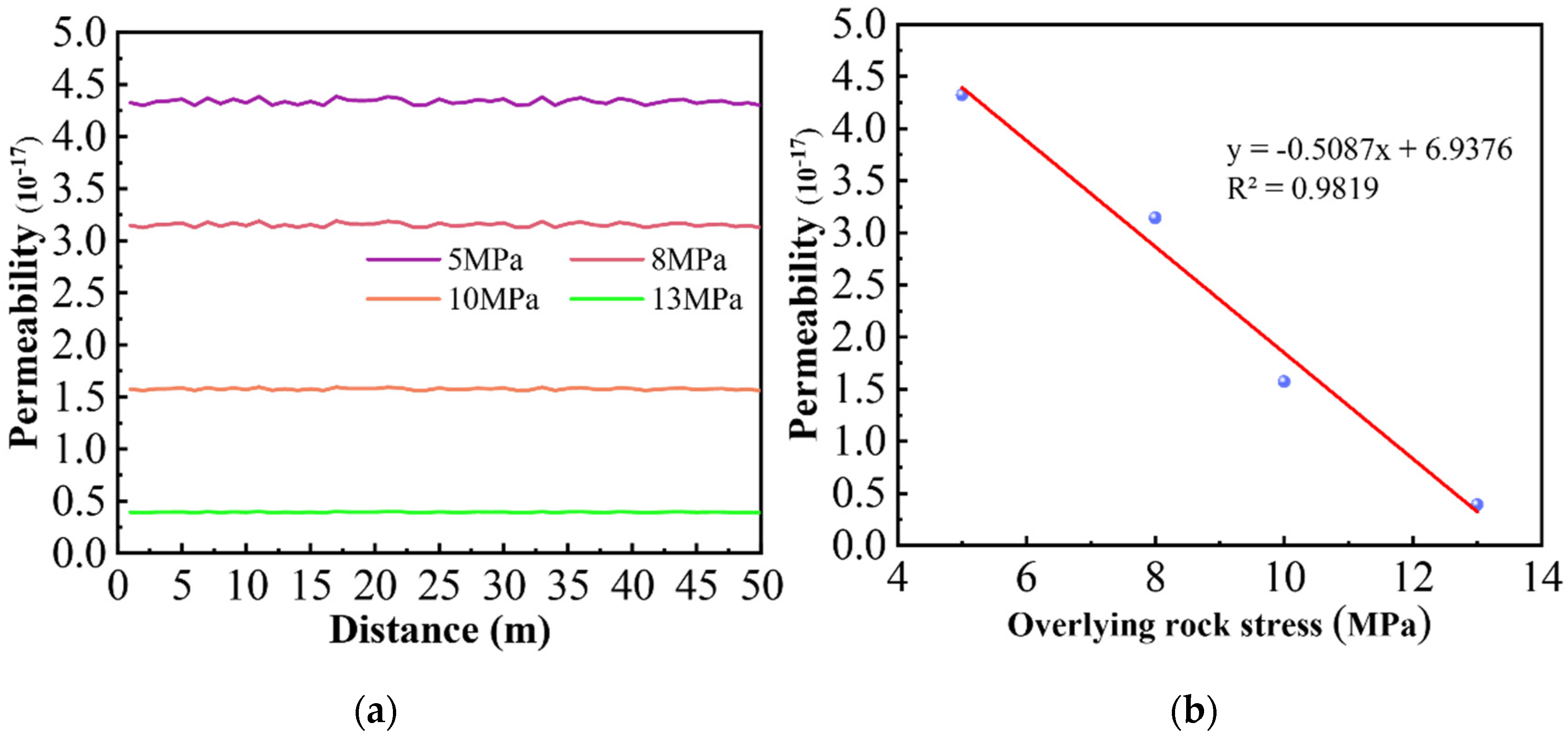
3.2.1. Change Rule of Key Strata Unloading Permeability

After hydraulic fracturing of the key layer, the permeability of the coal seam undergoes significant changes, as depicted in Figure 7a,b. Analyzing the changes in coal seam permeability during the stress unloading process in the key layer reveals that hydraulic fracturing disrupts the stress transfer path of the overlying rock layer, thereby enhancing the permeability of the coal seam. The extent of stress unloading directly impacts the degree of permeability enhancement. For overlying rock stresses of 13 MPa, 10 MPa, 8 MPa, and 5 MPa, the corresponding permeabilities were 3.95 × 10⁻¹⁸ m2, 1.56 × 10⁻¹⁷ m2, 3.14 × 10⁻¹⁷ m2, and 4.32 × 10⁻¹⁷ m2, respectively. Notably, permeability exhibits a linear relationship with stress, represented by the equation y = −0.5087x + 6.9376. This implies that higher overlying rock stresses result in lower permeability and, consequently, reduced gas extraction efficiency. Therefore, fracturing the key layer to relieve stress in the coal seam significantly enhances gas extraction effectiveness.

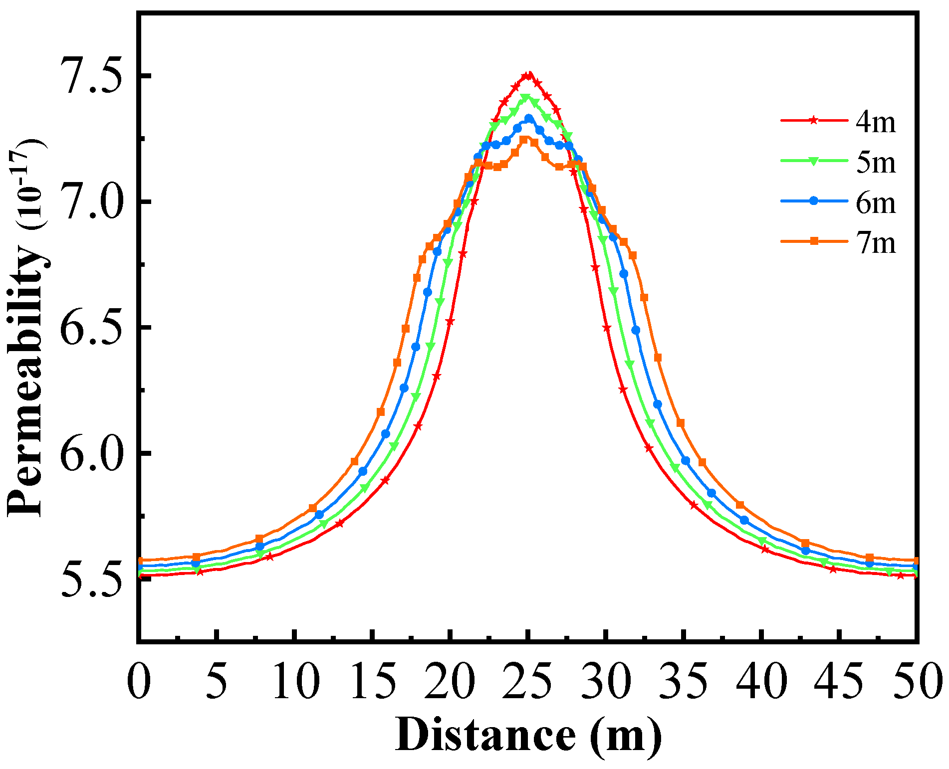
3.2.2. Change Rule in Permeability of Large-Diameter Borehole

In the process of gas drainage, the pore pressure of the coal seam continuously decreases, leading to desorption of the coal matrix and changes in effective stress, which, in turn, results in continuous changes in coal permeability. Figure 8 illustrates the simulated change in coal seam permeability during the extraction process using ordinary drilling and hole drilling. The results show that hole drilling has a greater impact on improving coal seam permeability compared to ordinary drilling, and the enhanced permeability range is also larger. The permeability of coal seams around ordinary boreholes reached 5.1 × 10⁻¹⁷ m2, with an influence range of approximately 5 m. However, when hole drilling was used, the permeability increased by about 1 × 10⁻¹⁷ m2 compared to ordinary drilling, and the influence range of permeability expanded to 10 m, showing a significant improvement.

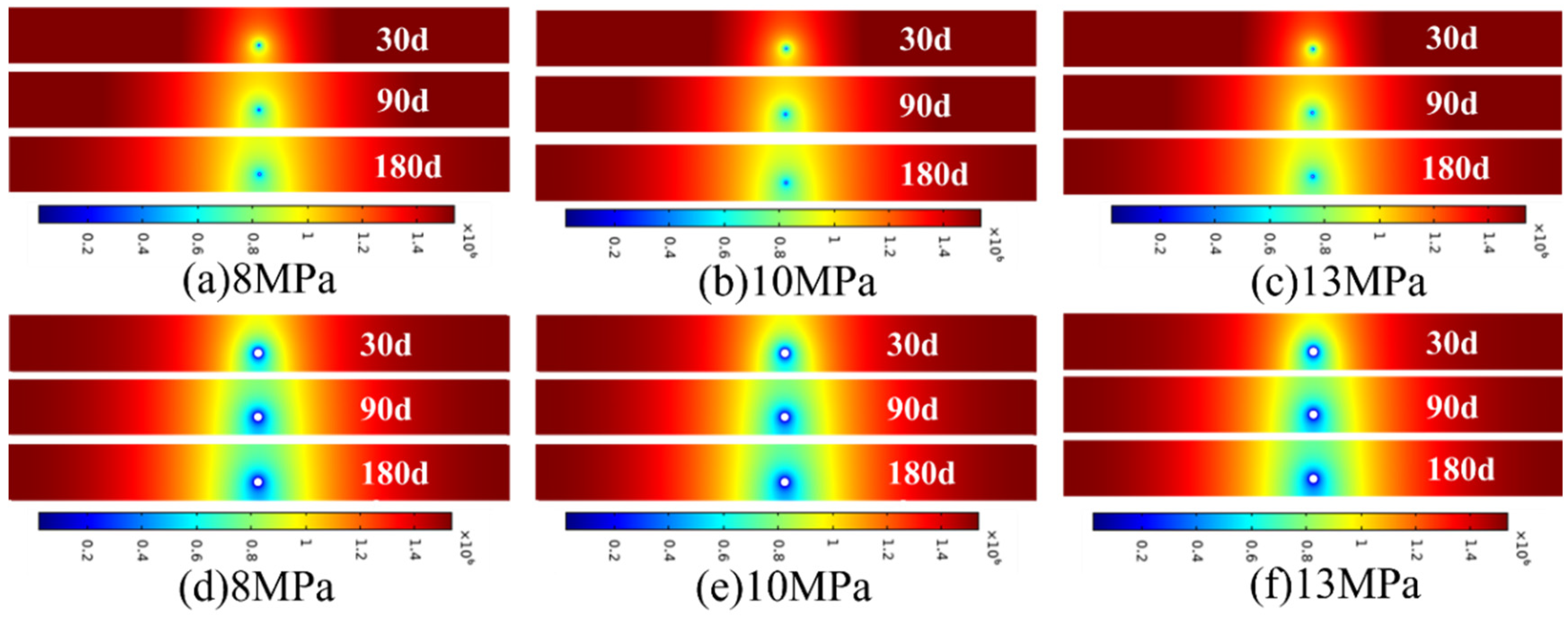
3.2.3. Change Rule of Double Unloading Permeability

The method of hydraulic fracturing was employed to reduce the overburden rock stress from 13 MPa to 9.65 MPa. The unloading pressure was approximately 3.35 MPa. The permeability of the coal seams was monitored for different borehole spacing (4 m, 5 m, 6 m, and 7 m), and the comprehensive permeability of the coal seams is illustrated in Figure 9. Initially, the permeability of the coal seam was 3.95 × 10⁻¹⁸ m2 when it was not fractured or subjected to large-diameter burrowing. However, by combining the method of fracturing the key strata with large-diameter burrowing, the permeability increased to a range of 5.59 × 10⁻¹⁷ m2 to 7.46 × 10⁻¹⁷ m2. When the spacing of drilling holes was 4 m, the permeability of coal seam was the largest, reaching 7.46 × 10⁻¹⁷ m2, but its anti-reflection range was also the smallest. As the spacing of drilling holes increases to 5 m and 6 m, the permeability of coal seam gradually decreases. When the spacing of drilling holes was 7 m, the average permeability of coal seam was 6.45 × 10⁻¹⁷ m2 and the anti-reflection range was up to 30 m. For the soft coal seam boring process, the use of key layer hydraulic fracturing and the coal seam large-diameter hole-making method for field tests can overall improve the level of gas management in the working face.

3.3. Drilling and Extraction Rules before and after Stress Relief of Key Strata

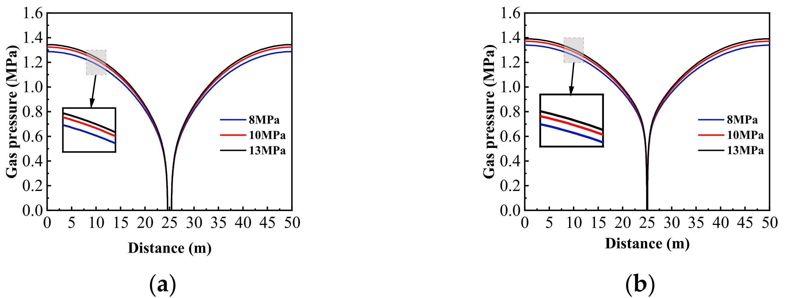
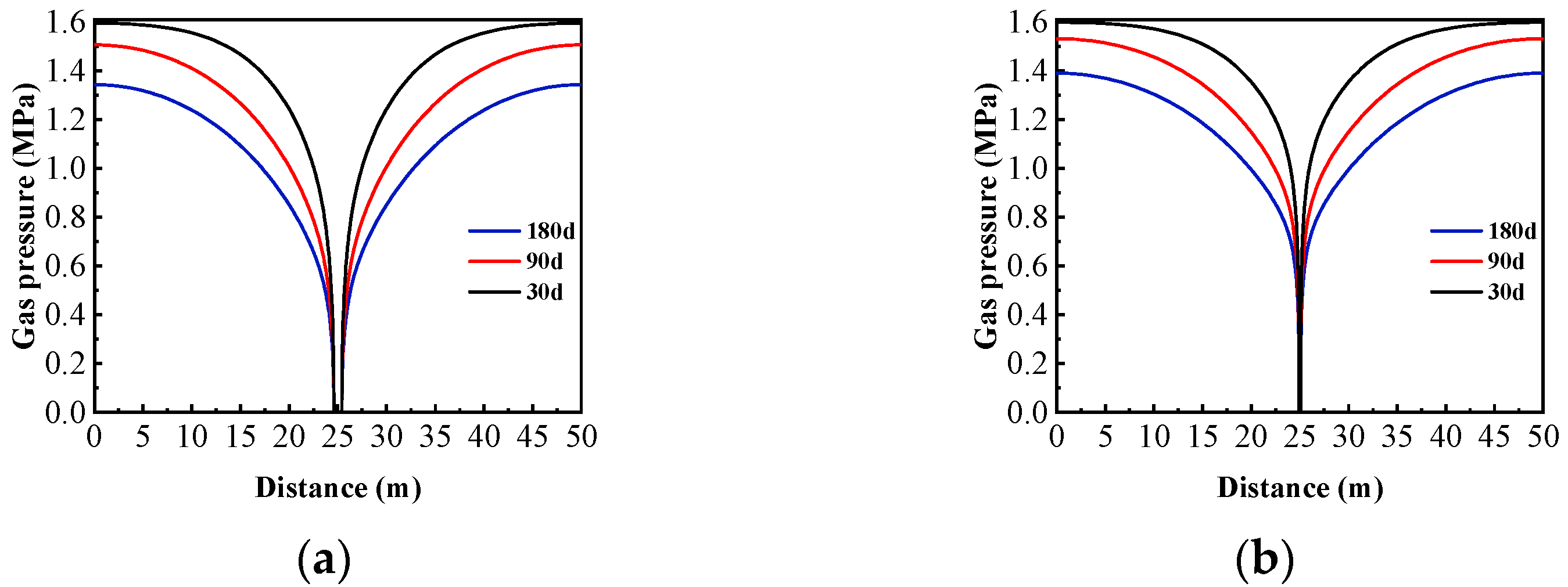
3.3.1. Gas Pressure Distribution in Extraction Boreholes

Gas extraction is a long-term process; usually coal mines use 180 d as an extraction cycle, so the number of days of extraction for the coal seam was monitored for 30 d, 90 d, and 180 d, and the gas pressure distribution cloud map was plotted when the stress of the overlying rock layer on the coal seam was gradually depressurized from 13 MPa to 10 MPa and 8 MPa as shown in Figure 10. Subfigures a–c illustrate the cloud maps of the extraction pressure for ordinary boreholes over time, while subfigures d–f depict the cloud maps of the extraction pressure for hole drilling over time. The results demonstrate that the pressure relief effect of the overlying strata of the coal seam can enhance the gas extraction range of the coal seam drilling with increasing extraction time. Furthermore, within the same extraction time, the gas extraction pressure reduction range of the hole drilling was significantly greater than that of the ordinary extraction drilling. As shown in Figure 10d, the rate of decrease in gas pressure during the extraction time from 30 d to 90 d is significantly larger than that from 90 d to 180 d, and it can be predicted that the rate of decrease of gas pressure after 180 d is even slower.
According to the difference in stress of the overlying rock layer, the gas pressure extraction curves of hole drilling and ordinary drilling at 180 d of extraction were plotted, as shown in Figure 11. There is a difference in the gas pressure drop rate under different stress levels of the overlying rock layer, and the gas pressure drop rate of coal seam with overburden stress of 8 MPa was faster than that of coal seam with overburden stress of 13 MPa; this indicates that the greater the degree of decompression of overburden, the more obvious the effect of gas pressure drop of the coal seam is. As shown in Figure 11a, with the overburden stress of 8 MPa, the gas pressure at 25 m away from the extraction borehole is 1.29 MPa, which is lower than that of the ordinary borehole of 1.35 MPa. Therefore, under the same stress of the overlying rock layer, the range and speed of gas pressure decrease of the hole drilling is larger than that of the ordinary drilling. As shown in Figure 12, when the stress of the overlying rock layer is 13 MPa, with the increase in the number of days of extraction, the decrease in gas pressure in the hole drilling is larger than that in the ordinary drilling; the gas pressure in the hole making drilling decreases from 1.6 MPa to 1.33 MPa, while the gas pressure in the ordinary drilling decreases from 1.6 MPa to 1.4 MPa. In the same period of time of extraction, the decrease in the gas pressure of the two sides of the hole drilling is greater than that of the ordinary drilling.

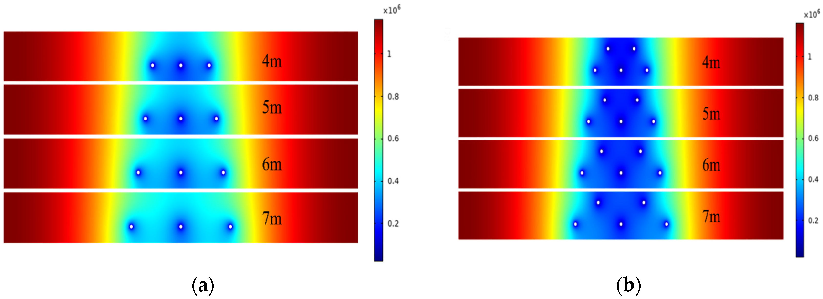
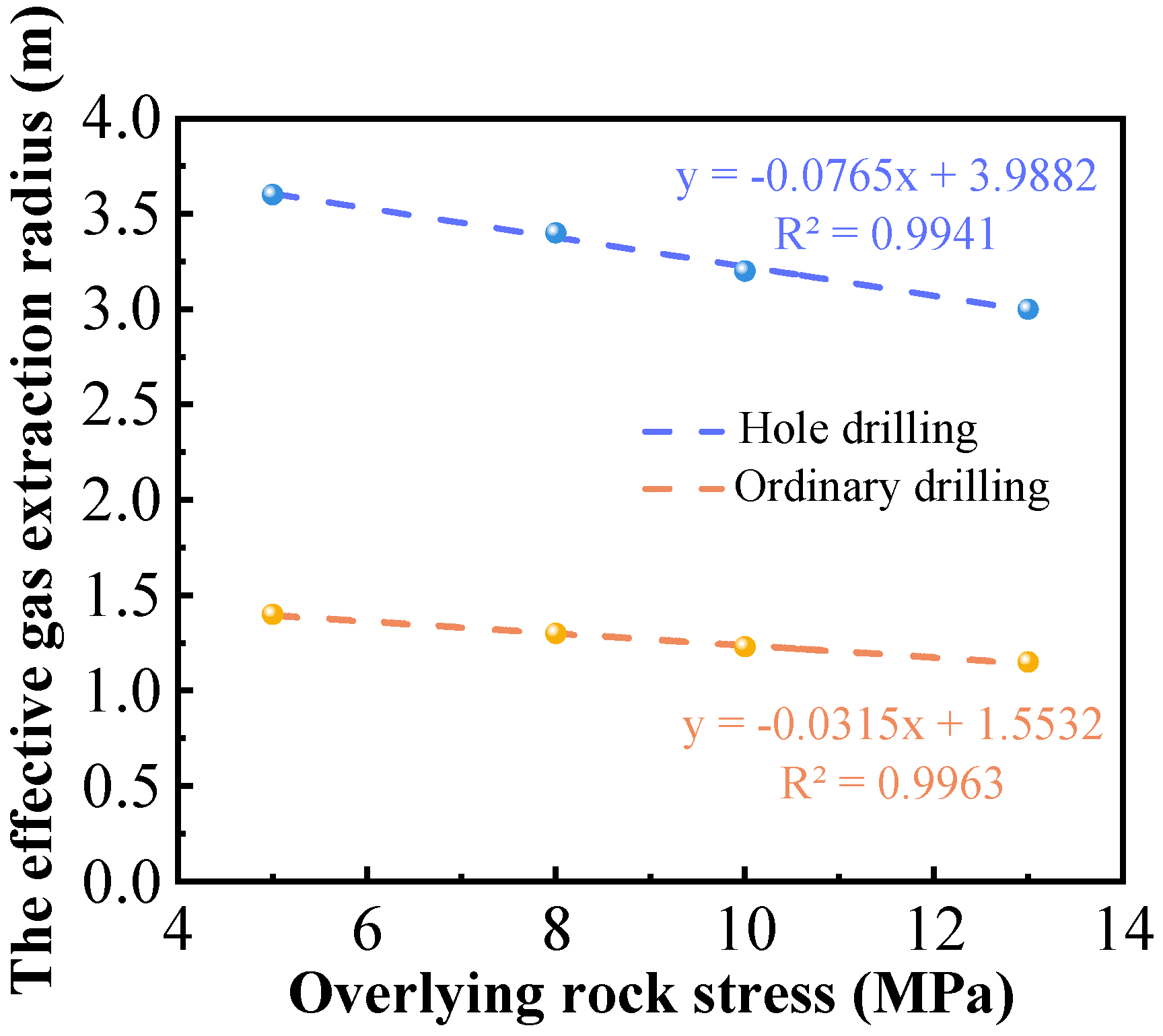
3.3.2. Effective Extraction Radius

According to the findings in Figure 13, it is evident that the effective extraction radius increases as the stress load of the overlying rock formation decreases and as the borehole diameter increases. For stress loads of 13 MPa, 10 MPa, 8 MPa, and 5 MPa in the overlying rock layer, the effective extraction radius of the hole drilling was measured to be 3 m, 3.2 m, 3.4 m, and 3.6 m, respectively. On the other hand, the extraction radius of the ordinary borehole was found to be 1.15 m, 1.23 m, 1.3 m, and 1.4 m. These results can be attributed to the expansion and deformation of the coal matrix and the opening up of pore fissures in the coal layer. This suggests that an increase in overburden stress within the coal seam significantly hinders gas extraction, while increasing the diameter of boreholes can help expand the effective extraction radius. Consequently, unloading coal seam stress through hydraulic fracturing and large-diameter borehole technology in overlying strata can effectively improve the extraction effect.

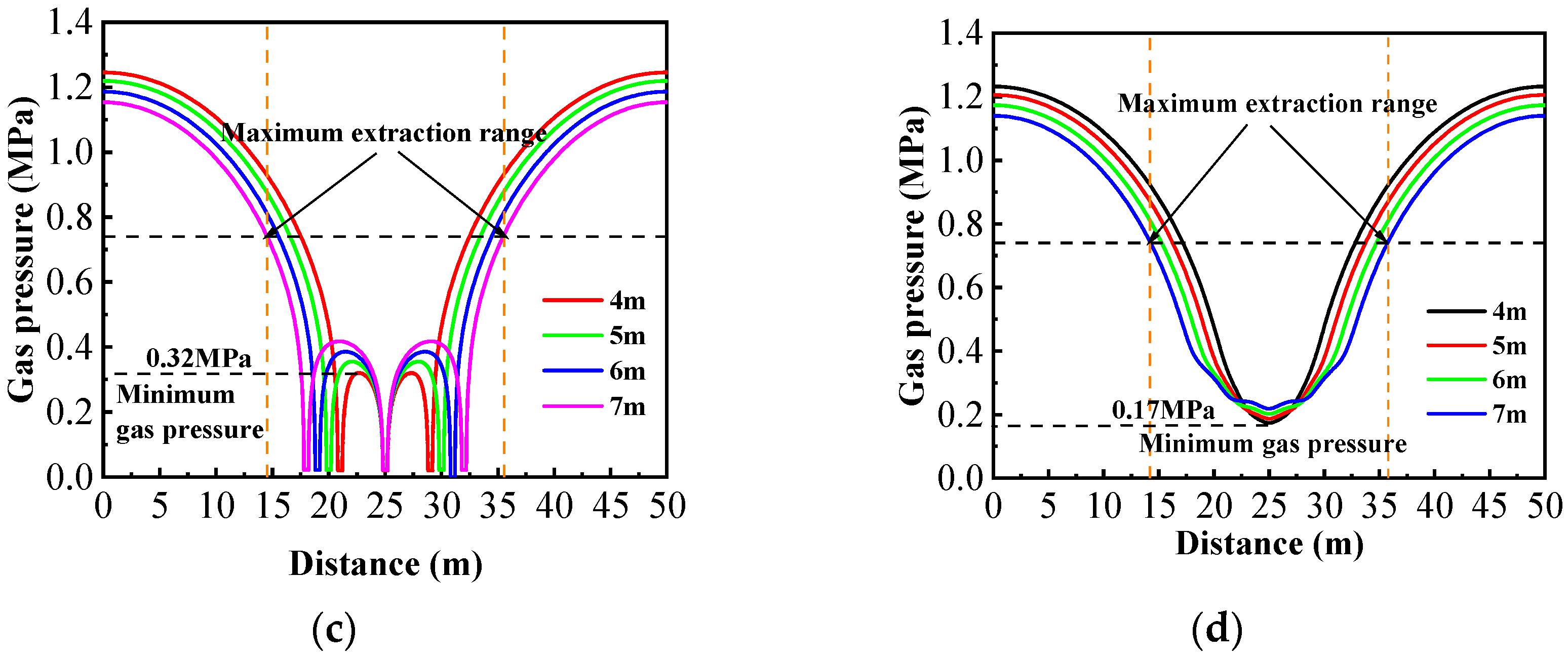
3.3.3. Optimization of Hole Drilling Arrangement Parameters

Through a numerical simulation study of single-hole extraction, it has been concluded that the effective extraction radius and gas pressure drop rate of coal seam hole drilling are significantly larger compared to ordinary drilling. Furthermore, after fracturing the key strata of the overlying rock layer, the effective extraction radius of hole drilling becomes even larger. Based on this, it is determined that hole drilling should be adopted and the process of drilling holes should be optimally arranged. The simulation in Figure 14 shows the use of single-row and double-row drill holes, with varying spacing of 4 m, 5 m, 6 m, and 7 m. The double-row drill holes are arranged in a ‘triple-eyelet’ configuration, with a spacing of 2.5 m between the upper and lower rows. According to Figure 14a,b, it can be seen that the effective range enhancement of borehole extraction is greater than 2 times the effective extraction radius, due to the superposition effect of the effective extraction radius of the borehole. Additionally, the use of the triangular double-row layout expands the extraction range of the holes, effectively addressing the gas control blank area at the top and bottom plates of the coal seam, which is not adequately addressed by a single row of holes.
The results shown in Figure 14c indicate that the gas pressure at the center of the adjacent drill holes is 0.32 MPa, 0.34 MPa, 0.38 MPa, and 0.41 MPa for drill hole spacings of 4 m, 5 m, 6 m, and 7 m, respectively. The maximum pressure relief range is found to be 21 m. Similarly, in the case of Figure 14d with double rows of holes, the gas pressures at the center of the adjacent holes are 0.17 MPa, 0.19 MPa, 0.21 MPa, and 0.23 MPa for drill hole spacings of 4 m, 5 m, 6 m, and 7 m and the maximum pressure relief range is also 21 m. It can be concluded that the pressure relief range of double-row holes is greater in the longitudinal direction, while remaining consistent with that of the single-row holes in the transverse direction. Additionally, the gas pressure decreases faster in double-row drill holes within the same extraction time, with the lowest gas pressure reaching 0.17 MPa. This suggests that double-row drill holes can more effectively reduce the gas level in the coal seam below the safety threshold.

4. Field Practice Effect Analysis

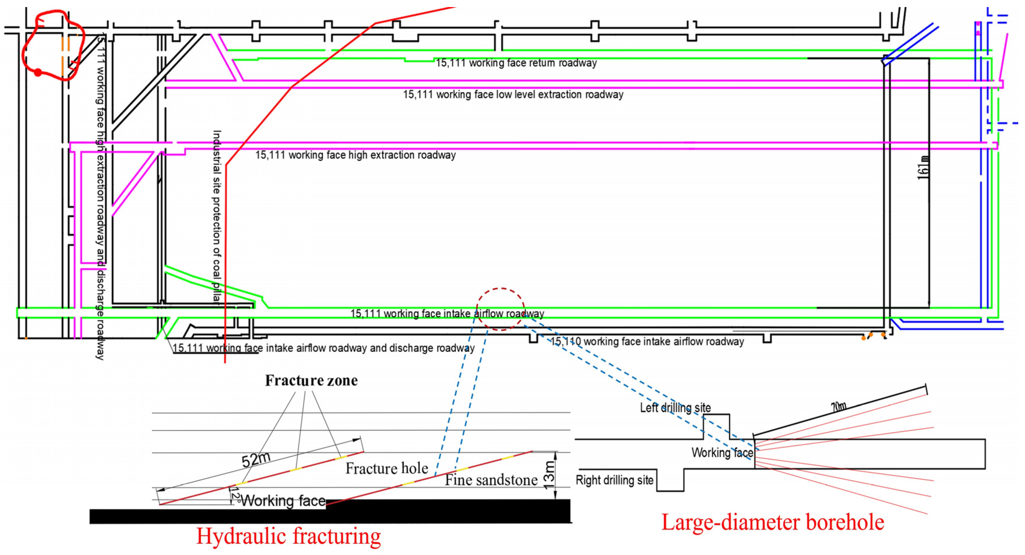
4.1. Working Face Conditions and Drilling Arrangement

The test site is located in the boring face of a mine in Shanxi, as depicted in Figure 15. The designed fracturing drill hole has a height of 1.5 m, an azimuth angle (angle with the centerline of the roadway) of 0°, an inclination angle of 12°, and a hole depth of 52 m. On the other hand, the observation drill hole has a height of 1.5 m, a horizontal distance of 3 m from the fracturing hole, an azimuth angle of 20°, an inclination angle of 12°, and a hole depth of 55 m. Following the hydraulic fracturing of the key layer, the extraction is carried out using the ‘triangular shape’ drilling method with double rows of holes. Six large-diameter coal seam drill holes are arranged parallel to the vertical coal wall face in the boring face. The design parameters of the extraction drill holes are as follows: negative pressure of 20 kPa, hole diameter of 400 mm, hole spacing of 5.0 m, and hole depth of 70 m.

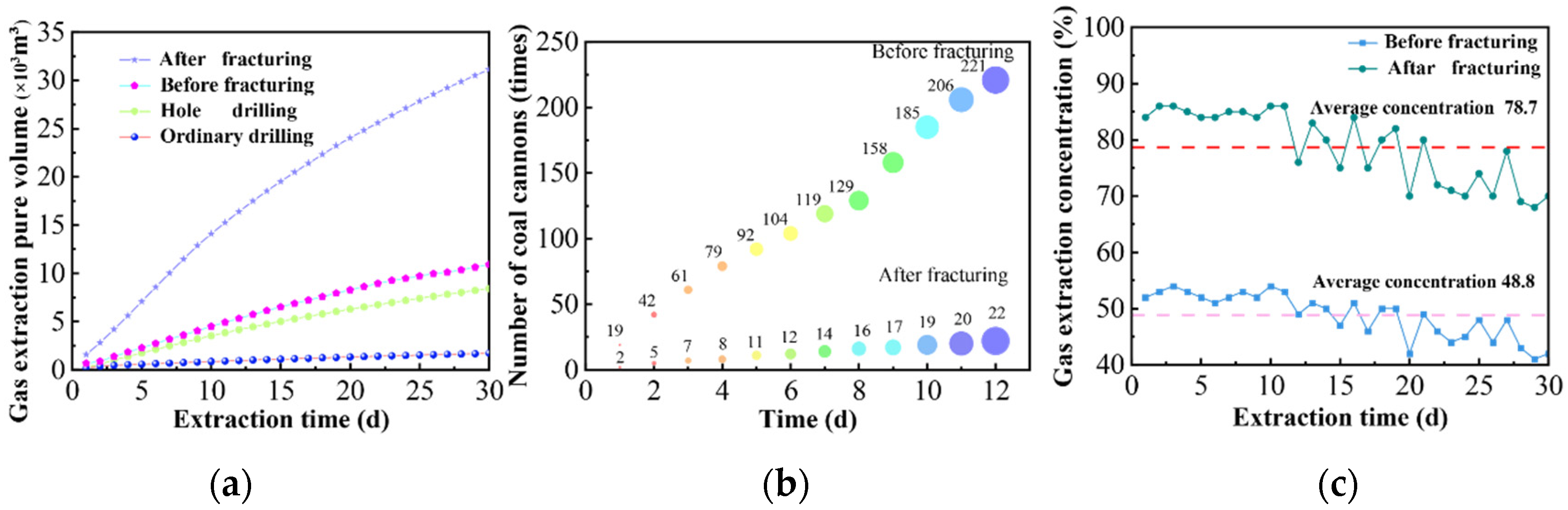
4.2. On-Site Implementation

By monitoring the extraction data before and after fracturing of ordinary drilling and hole drilling, the pure amount of gas extracted from ordinary drilling and hole drilling before and after fracturing of the key strata, the cumulative number of coal blasts before and after unloading pressure, and the comparison of the amount of gas extracted before and after unloading and the concentration of the gas extracted are plotted, as shown in Figure 16. The analysis reveals that before fracturing in the key strata the cumulative 30-day pure gas extraction volume from ordinary drilling was 1713 m3, whereas hole drilling yielded a 30-day pure gas extraction volume of 8412 m3 after fracturing. Furthermore, the cumulative 30-day pure gas extraction volume at the drilling site before unloading pressure was 10,891 m3, which significantly increased to 31,183 m3 after unloading pressure was applied. Comparing the cumulative number of coal cannons before and after fracturing, the key strata indicates that decompressing the key strata can greatly reduce the occurrence of coal cannons, resulting in a reduction of more than 90% in their frequency.
The results of the field application indicate that adopting hydraulic fracturing of key layers and implementing large-diameter borehole technology in coal seams can significantly enhance gas extraction. The cumulative 30-day pure amount of gas extracted from using large-diameter gas extraction boreholes was approximately five times higher compared to ordinary drilling without fracturing. Furthermore, the gas extraction concentration at the hole drilling field after fracturing was 1.6 times higher than that of the ordinary drilling field without depressurization. Additionally, the cumulative 30-day pure amount of gas extraction at the fracturing drilling site was 2.9 times higher than the non-fractured drilling field. These findings demonstrate that hydraulic fracturing of key strata and the use of large-diameter borehole technology in soft coal seams effectively depressurizes and increases the permeability of the coal body, resulting in a significant improvement in gas extraction efficiency

5. Conclusions

  • Following hydraulic fracturing of the overlying key strata, a new stress field known as the ‘three zones’ was created. The average peak stress on both sides of the coal seam roadway decreased by 3.35 MPa, with the energy peak decreasing by over 40% and the stress concentration area shrinking by approximately 2 m. These findings suggest that hydraulic fracturing of the key strata has a substantial impact on the unloading and dissipation of stress and energy within the coal seam.
  • The study of stress effects on coal seam permeability revealed a significant increase in permeability through hydraulic fracturing and large-diameter cavity drilling technology. The maximum enhancement observed was up to 190 times, suggesting that reducing overlying rock stress and increasing drill hole diameter can enhance gas extraction from coal seams.
  • A gas extraction model was developed to address the issue of multi-row drilling in thick coal beds, considering the impact of overburden stress. Through simulations of various hole spacing configurations and on-site validation, ‘triangular’ hole spacing of 5 m was determined as the most effective solution. This spacing successfully addressed the limitation of single-row hole spacing in influencing the coal bed longitudinally.

Author Contributions

Methodology, F.L.; software, Z.Y.; investigation, J.X.; resources, J.H.; Data curation, F.L.; writing—original draft preparation, Z.Y.; writing—review and editing, F.L.; project administration, J.X.; funding acquisition, F.L. All authors have read and agreed to the published version of the manuscript.

Funding

This study was financially supported by National Natural Science Foundation of China (52064046, 51804311), The Fundamental Research Funds for the Central Universities (2023ZKPYAQ03) and the Special Project for Regional Collaborative Innovation of Xinjiang Autonomous Region [Science and technology assistance plan for Xinjiang] (2020E0258).

Institutional Review Board Statement

Not applicable.

Informed Consent Statement

Not applicable.

Data Availability Statement

The data used to support the findings of this study are available from the corresponding authors upon request.

Conflicts of Interest

Authors Xie, J. and Huo, J. were employed by the company “Lu’an Chemical Sijiazhuang Co., Ltd.”. The remaining authors declare that the research was conducted in the absence of any commercial or financial relationships that could be construed as a potential conflict of interest.

References

  1. Wang, L.; Cheng, Y.; Wang, L.; Guo, P.; Li, W. Safety line method for the prediction of deep coal-seam gas pressure and its application in coal mines. Saf. Sci. 2012, 50, 523–529. [Google Scholar] [CrossRef]
  2. Wang, L.; Liu, S.; Cheng, Y.; Yin, G.; Guo, P.; Mou, J. The effects of magma intrusion on localized stress distribution and its implications for coal mine outburst hazards. Eng. Geol. 2017, 218, 12–21. [Google Scholar] [CrossRef]
  3. Cheng, Y.; Pan, Z. Reservoir properties of Chinese tectonic coal: A review. Fuel 2020, 260, 116350. [Google Scholar] [CrossRef]
  4. Kursunoglu, N.; Onder, M. Application of structural equation modeling to evaluate coal and gas outbursts. Tunn. Undergr. Space Technol. 2019, 88, 63–72. [Google Scholar] [CrossRef]
  5. Zhao, B.; Cao, J.; Sun, H.; Wen, G.; Wang, B. Experimental investigations of stress-gas pressure evolution rules of coal and gas outburst: A case study in Ding ji coal mine, China. Energy Sci. Eng. 2020, 8, 61–73. [Google Scholar] [CrossRef]
  6. Zhou, A.; Xu, Z.; Wang, K.; Wang, Y.; An, J.; Shi, Z. Coal mine gas migration model establishment and gas extraction technology field application research. Fuel 2023, 349, 128650. [Google Scholar] [CrossRef]
  7. Zhao, P.; Zhuo, R.; Li, S.; Shu, C.; Laiwang, B.; Jia, Y.; Suo, L. Analysis of advancing speed effect in gas safety extraction channels and pressure-relief gas extraction. Fuel 2020, 265, 116825. [Google Scholar] [CrossRef]
  8. Liu, Y.; Zhang, C.; Song, Z. Numerical simulation of surface gas venthole extraction and the effect of ventilation mode in pressure-relief mining. Processes 2022, 10, 750. [Google Scholar] [CrossRef]
  9. Zhou, B.; Xu, J.; Yan, F.; Peng, S.; Gao, Y.; Li, Q.; Cheng, L. Effects of gas pressure on dynamic response of two-phase flow for coal-gas outburst. Powder Technol. 2021, 377, 55–69. [Google Scholar] [CrossRef]
  10. Zou, Q.; Liu, H.; Zhang, Y.; Li, Q.; Fu, J.; Hu, Q. Rationality evaluation of production deployment of outburst-prone coal mines: A case study of nantong coal mine in Chongqing, China. Saf. Sci. 2020, 122, 104515. [Google Scholar] [CrossRef]
  11. Chen, H.; Cheng, Y.; Ren, T.; Zhou, H.; Liu, Q. Permeability distribution characteristics of protected coal seams during unloading of the coal body. Int. J. Rock Mech. Min. 2014, 71, 105–116. [Google Scholar] [CrossRef]
  12. Lou, Z.; Wang, K.; Zang, J.; Zhao, W.; Qin, B.; Kan, T. Effects of permeability anisotropy on coal mine methane drainage performance. J. Nat. Gas Sci. Eng. 2021, 86, 103733. [Google Scholar] [CrossRef]
  13. Chen, H.; Chen, Y.; Zhou, H.; Li, W. Damage and permeability development in coal during unloading. Rock Mech. Rock Eng. 2013, 46, 1377–1390. [Google Scholar] [CrossRef]
  14. Wang, L.; Lu, Z.; Chen, D.; Liu, Q.; Chu, P.; Shu, L.; Wen, Z. Safe strategy for coal and gas outburst prevention in deep-and-thick coal seams using a soft rock protective layer mining. Saf. Sci. 2020, 129, 104800. [Google Scholar] [CrossRef]
  15. Cheng, Y.; Wang, L.; Liu, H.; Kong, S.; Yang, Q.; Zhu, J.; Tu, Q. Definition, theory, methods, and applications of the safe and efficient simultaneous extraction of coal and gas. IJCST 2015, 2, 52–65. [Google Scholar] [CrossRef]
  16. Zou, Q.; Liu, H.; Jiang, Z.; Wu, X. Gas flow laws in coal subjected to hydraulic slotting and a prediction model for its permeability-enhancing effect. Energy Sources Part A 2021, 7, 1–15. [Google Scholar] [CrossRef]
  17. Lin, B.; Yan, F.; Zhu, C.; Zhou, Y.; Zou, Q.; Guo, C.; Liu, T. Cross-borehole hydraulic slotting technique for preventing and controlling coal and gas outbursts during coal roadway excavation. J. Nat. Gas Sci. Eng. 2015, 26, 518–525. [Google Scholar] [CrossRef]
  18. Fan, C.; Li, S.; Luo, M.; Yang, Z.; Lan, T. Numerical simulation of hydraulic fracturing in coal seam for enhancing underground gas drainage. Energy Explor. Exploit. 2019, 37, 166–193. [Google Scholar] [CrossRef]
  19. Wang, T.; Zhou, W.; Chen, J.; Xiao, X.; Li, Y.; Zhao, X. Simulation of hydraulic fracturing using particle flow method and application in a coal mine. Int. J. Coal Geol. 2014, 121, 1–13. [Google Scholar] [CrossRef]
  20. Wang, W.; Li, X.; Lin, B.; Zhai, C. Pulsating hydraulic fracturing technology in low permeability coal seams. IJMST 2015, 25, 681–685. [Google Scholar] [CrossRef]
  21. Yew, C.H. Mechanics of Hydraulic Fracturing, 1st ed.; Gulf Publishing: Houston, TX, USA, 1997; pp. 39–43. [Google Scholar]
  22. Wang, L.; Xu, Y. Study of the law of gradual change of the influence of hydraulic punching under a rational coal output. Arab. J. Geosci. 2019, 12, 427. [Google Scholar] [CrossRef]
  23. Gu, B.; Wu, Y. Research and application of hydraulic punching pressure relief antireflection mechanism in deep “Three-Soft” outburst coal seam. Shock Vib. 2021, 2021, 7241538. [Google Scholar] [CrossRef]
  24. Li, Y.; Jiang, T.; Guo, X. Research on gas extraction technology of directional long borehole in ultrathick coal seam. Geofluids 2022, 2022, 6957896. [Google Scholar] [CrossRef]
  25. Wang, H.; Cheng, Y.; Yuan, L. Gas outburst disasters and the mining technology of key protective seam in coal seam group in the Huainan coalfield. Nat. Hazards 2013, 67, 763–782. [Google Scholar] [CrossRef]
  26. Ni, G.; Lin, B.; Zhai, C. Impact of the geological structure on pulsating hydraulic fracturing. Arab. J. Geosci. 2015, 8, 10381–10388. [Google Scholar]
  27. Liu, L.; Liu, M.; Wei, J. Regional outburst-prevention technique by gas pre-drainage based on large diameter boreholes along coal seams under deep mining. Procedia Eng. 2011, 26, 623–629. [Google Scholar]
  28. Wang, T.; Hu, W.; Elsworth, D.; Zhou, W.; Zhou, W.; Zhao, X.; Zhao, L. The effect of natural fractures on hydraulic fracturing propagation in coal seams. J. Petrol. Sci. Eng. 2017, 150, 180–190. [Google Scholar] [CrossRef]
  29. Ma, Y.; Mao, X.; Yang, K.; Liu, J.; Zhao, A. Improvement on gas drainage of soft gassy coal seam with underground hydraulic flushing and fracturing: A case study in Huainan. Arab. J. Geosci. 2020, 13, 178. [Google Scholar] [CrossRef]
  30. Zhang, R.; Hao, C. Research on the development of hydraulic flushing caverning technology and equipment for gas extraction in soft and low permeability tectonic coal seams in China. ACS Omega 2022, 7, 21615–21623. [Google Scholar] [CrossRef]
  31. Lu, W.; Huang, B.; Zhao, X. A review of recent research and development of the effect of hydraulic fracturing on gas adsorption and desorption in coal seams. Adsorpt. Sci. Technol. 2019, 37, 509–529. [Google Scholar] [CrossRef]
  32. Zhou, B.; Xu, J.; Peng, S.; Yan, F.; Yang, W.; Cheng, L.; Ni, G. Influence of geo-stress on dynamic response characteristics of coal and gas outburst. Rock Mech. Rock Eng. 2020, 53, 4819–4837. [Google Scholar] [CrossRef]
  33. Zhang, D.; Yang, T. Environmental impacts of hydraulic fracturing in shale gas development in the United States. Petrol. Explor. Dev. 2015, 42, 876–883. [Google Scholar] [CrossRef]
  34. Xie, J.; Xu, J. Effect of key stratum on the mining abutment pressure of a coal seam. Geosci. J. 2017, 21, 267–276. [Google Scholar] [CrossRef]
  35. Li, M.; Zhang, J.X.; Huang, Y.; Gao, R. Measurement and numerical analysis of influence of key stratum breakage on mine pressure in top-coal caving face with super great mining height. J. Cent. South Univ. 2017, 24, 1881–1888. [Google Scholar] [CrossRef]
  36. Li, F.; Liu, H.; Wang, C.; Sun, R.; Xiang, G.; Ren, B.; Wang, G. Stress Relief and Permeability Enhancement with Hydraulic Fracturing in Overlying Key Strata of Deep and Soft Coal Seams. ACS Omega 2023, 8, 12183–12193. [Google Scholar] [CrossRef]
  37. Wei, P.; Huang, C.; Li, X.; Peng, S.; Lu, Y. Numerical simulation of boreholes for gas extraction and effective range of gas extraction in soft coal seams. Energy Sci. Eng. 2019, 7, 1632–1648. [Google Scholar] [CrossRef]
  38. Xia, T.; Gao, F.; Kang, J.; Wang, X. A fully coupling coal–gas model associated with inertia and slip effects for CBM migration. Environ. Earth Sci. 2016, 75, 582. [Google Scholar] [CrossRef]
  39. Hu, G.; Huang, X.; Xu, J.; Qin, W.; Wang, H. A co-extraction technology of coal and CBM based on the law of gas advanced relieving pressure of in-seam coalface. Disaster Adv. 2012, 5, 1351–1356. [Google Scholar]
Figure 1. Structural model of laminated combined coal rock body.
Applsci 14 03202 g001
Figure 2. Comprehensive geological histogram of 15,111 working face.
Applsci 14 03202 g002
Figure 3. Design and test of fracturing scheme for overlying strata.
Applsci 14 03202 g003
Figure 4. Model building and meshing. (a) Overburden fracturing model. (b) Geometric model of gas extraction.
Applsci 14 03202 g004
Figure 5. Stress change rule of coal seam before and after unloading of key strata. (a) Advanced stress nephogram of coal seam. (b) Stress nephogram after coal seam excavation. (c) Stress curve after coal seam excavation.
Applsci 14 03202 g005
Figure 6. Energy change rule of coal seam before and after unloading of key strata. (a) Advanced energy nephogram of coal seam. (b) Energy nephogram after coal seam excavation. (c) Energy curve after coal seam excavation.
Applsci 14 03202 g006
Figure 7. Variation in permeability of coal seams. (a) Stress permeability of different overburden rocks. (b) Stress and permeability fitting curves.
Applsci 14 03202 g007
Figure 8. Variation in permeability around boreholes.
Applsci 14 03202 g008
Figure 9. Variation in coal seam permeability.
Applsci 14 03202 g009
Figure 10. Gas pressure distribution under different overburden stresses.
Applsci 14 03202 g010
Figure 11. Variation curve of overlying rock stress and gas pressure overlying rock layers. (a) Hole drilling. (b) Ordinary drilling.
Applsci 14 03202 g011
Figure 12. Variation curve of extraction time and gas pressure. (a) Hole drilling. (b) Ordinary drilling.
Applsci 14 03202 g012
Figure 13. Fitting curve between effective gas extraction radius and overburden stress.
Applsci 14 03202 g013
Figure 14. Gas pressure distribution and change curve of different drill hole spacing and multi-row drill hole arrangements. (a) Gas pressure distribution in single row of holes. (b) Gas pressure distribution in double row of holes. (c) Variation curve of gas pressure in a single row of holes. (d) Variation curve of gas pressure in double row of holes.
Applsci 14 03202 g014aApplsci 14 03202 g014b
Figure 15. Design layout of drill holes on-site at the working face.
Applsci 14 03202 g015
Figure 16. Changes in pure volume of gas extraction and extraction concentration before and after fracturing of key strata. (a) Gas extraction. (b) Cumulative number of coal cannons before and after fracturing. (c) Gas extraction concentration before and after fracturing.
Applsci 14 03202 g016
Table 1. Physical and mechanical parameters of rock layers.
LithologyUnit Weight
kN/m3
Modulus of
Elasticity/GPa
Poisson’s
Ratio/μ
Compressive Strength/MPaTensile Strength
MPa
Internal Friction Angle °
Fine sandstone26180.221001042
Limestone26400.201201845
Sandy mudstone25150.2840338
Coal140.30.34100.628
Table 2. Coal seam gas related parameters.
Parameter NameNumerical ValueParameter NameNumerical Value
Initial crack rate0.012Langmuir pressure constant (MPa)2
Initial porosity0.049Maximum value of adsorbed gas (m3/t)28.8
Initial permeability (mD)0.004Molar mass of coal gas (L/mol)22.4
Initial gas pressure (MPa)1.6Density of coal (kg/m3)1380
Dynamic viscosity of gas (Pa·s)1.08 × 10⁻⁵Negative pressure (kPa)21
Elastic modulus of coal matrix (MPa)8139Poisson ratio (υ)0.34
Elastic modulus of coal (MPa)2713Single pore diffusion coefficient5.599 × 10−12
Klinkenberg factor (Pa)1.4 × 10⁵Constant amount of adsorbed gas b (MPa−1)0.494
Disclaimer/Publisher’s Note: The statements, opinions and data contained in all publications are solely those of the individual author(s) and contributor(s) and not of MDPI and/or the editor(s). MDPI and/or the editor(s) disclaim responsibility for any injury to people or property resulting from any ideas, methods, instructions or products referred to in the content.

