Article

Investigation into the Fracture Evolution Law of Overlying Strata Roof in Shallowly Buried “Three-Soft” Coal Seam Fully Mechanized Mining Faces and Its Influence on the Feasibility of Gob-Side Entry Retaining

Key Laboratory of In-Situ Modified Mining Ministry of Education, Taiyuan University of Technology, Taiyuan 030024, China
*
Author to whom correspondence should be addressed.
Appl. Sci. 2025, 15(9), 4607; https://doi.org/10.3390/app15094607
Submission received: 3 April 2025 / Revised: 17 April 2025 / Accepted: 19 April 2025 / Published: 22 April 2025
(This article belongs to the Special Issue Advances in Green Coal Mining Technologies)

Abstract

:
To address the feasibility of gob-side entry retaining in the shallow-buried three-soft coal seam fully mechanized mining face (SB-TSCS FMMF) of Xindeng (Zhengzhou, China) Coal Industry, we established a mechanical model of post-mining roof–coal-rock interaction in shallow-buried three-soft coal seams. This study reveals the quantitative relationships between the fracture position of the main roof and parameters such as coal seam thickness and immediate roof elastic modulus, and determines the parameter conditions required for implementing gob-side entry retaining in SB-TSCS FMMF. Critical parameters for the main roof fracture under this geological condition were first identified through particle flow simulation. The results indicate that there exist quantitative relationships between the main roof fracture position and parameters of the coal seam and the immediate roof. The influence degree on the maximum force exerted by the main roof on underlying coal-rock strata decreases in descending order as follows: immediate roof elastic modulus, coal seam thickness, immediate roof thickness, and coal seam elastic modulus. Similarly, the influence degree on the maximum bending moment follows the same order: immediate roof elastic modulus, coal seam thickness, immediate roof thickness, and coal seam elastic modulus. Based on the roof fracture laws, parameter thresholds suitable for gob-side entry retaining in three-soft coal seams are proposed, such as coal seam thickness (≤4 m) and immediate roof thickness (≤8 m). It is found that the main roof fracture position in shallow-buried three-soft coal seams is concentrated within the 0.3–0.6 m stress-sensitive zone at the edge of the goaf, providing key parameter thresholds for the support design of gob-side entry retaining.

1. Introduction

With the large-scale exploitation of coal resources, under the traditional mining mode of leaving coal pillars, the cost of roadway excavation has been increasing significantly. In order to respond to the development concept of green mining and reduce the waste of coal resources, pillarless mining technology has begun to be widely applied in the coal industry. The application of gob-side entry retaining technology avoids the resource waste caused by the traditional method of leaving coal pillars and also reduces the amount of roadway excavation [1,2,3].
There are some technical problems in the application of pillarless gob-side entry retaining technology, such as large deformation and damage to the surrounding rock of the roadway caused by mining influence and problems with the support structure. However, based on the synergistic effect of mine pressure driving and the theory of rock swelling and self-stabilization, this technology achieves the dynamic balance of the surrounding rock stress in the stope through in situ solidification and filling of the goaf, effectively controlling the deformation of the overlying strata [4,5,6]. When implementing gob-side entry retaining in the fully mechanized mining face of shallow-buried “three-soft” coal seams, due to its unique geological characteristics, the fully mechanized mining face still faces severe challenges in implementing gob-side entry retaining. Therefore, it is necessary to study the fracture characteristic laws of the overlying roof in the fully mechanized mining face to determine whether the conditions for gob-side entry retaining are met. According to relevant mechanical theories, such as the thin-plate theory, after the working face has mined a certain distance forward from the cut-off position, the main roof reaches its strength limit and fractures in the goaf to form key rock blocks A, B, and C. Among them, the fracture position and movement form of key rock block B play a very important role in the stability of the surrounding rock of the gob-side roadway [7,8,9,10,11].
In recent years, many researchers have carried out a large number of studies on the fracture characteristics of the overlying roof. Gao, L. et al. [12] addressed the problem of surrounding rock deformation and instability in gob-side coal and rock roadways of inclined coal seams. Based on the influence of different main roof fracture locations on surrounding rock stress and displacement, they revealed the intrinsic relationship between fracture types and roadway stability. Yang, D. et al. [13] focused on the deformation and instability of gob-side entry retaining with soft rock composite roofs, constructing a mechanical model of a key block structure. By predicting the main roof fracture line position, analyzing the roof subsidence law on the backfill side, and combining numerical simulations, they revealed the plastic zone expansion and stress distribution characteristics induced by the main roof fracture rotation, providing a basis for roadway stability control. Chen, D. et al. [14] tackled the issues of main roof fracture and roadway instability caused by narrow coal pillars in gob-side entry driving. Using the block beam theory, they established an elastic foundation beam model, derived expressions for roof bending moment and displacement to determine fracture locations, and analyzed the impact of different fracture scenarios on surrounding rock stability through numerical simulations, solving the problems of main roof fracture and roadway instability induced by narrow coal pillars in gob-side entry driving. Yu, B. et al. [15] studied the disturbance height of the overlying strata and the fracture characteristics of the hard roof in the mining of extra-thick coal seams through on-site measurement and three-dimensional physical similar simulation methods, and explained the large and small cycles and the strong mine pressure manifestations in the large-space stope. Liu, J. et al. [16] constructed a physical similarity model to investigate the fracture characteristics of hard main roofs in large mining height fully mechanized top-coal caving faces, revealing three fracture positions and two structural patterns as the working face advances. Through a mechanical model, they analyzed the superimposed effects of large and small periodic mine pressure induced by different fracture modes, and proposed hydraulic fracturing technology to pre-split the roof, thereby weakening the dynamic load caused by composite structure instability. This study provides a basis for the stability control of roadways in such mining conditions. Certainly, the stability of gob-side entry roadways can also be considered for inversion prediction through real-time monitoring of hydraulic support loads and surrounding rock stress in the roadways [17]. Xu, G. et al. [18] analyzed the evolution law of the roof mine pressure in the fully mechanized top-coal caving face based on the zonal bearing mechanical model of the caving roof, proposed the calculation method for the evolution of the roof mine pressure in the large-mining-thickness fully mechanized top-coal caving face and the criterion for support crushing, and predicted the support crushing disasters in the fully mechanized top-coal caving face. For geological conditions in different countries, such as the Guangning Coal Field in Vietnam [19] and the Karaganda Coal Field in Kazakhstan [20], this method can also be used to conduct a preliminary assessment of the application feasibility when implementing gob-side entry retaining. Reference [21] indicates that the total thickness extraction of thick coal seams in a single lift must be adapted to seam conditions (e.g., thickness, rock mass behavior, and stress environment). It was found that a compressive strength of 25 MPa in coal serves as a critical threshold for the successful application of longwall top-coal caving (LTCC), providing valuable insights for similar mining engineering practices.
However, the fracture characteristics of the roof in three-soft coal seams differ from those under conventional geological conditions. To address the feasibility of implementing gob-side entry retaining projects in shallow-buried three-soft coal seam fully mechanized mining faces (SB-TSCS FMMFs), this study establishes an elastic foundation beam model for SB-TSCS FMMFs through a combination of theoretical analysis and particle flow numerical simulation. It reveals the quantitative relationships between the main roof fracture position and coal seam/roof parameters, investigates the movement characteristics of roof strata under different parameter conditions, and proposes parameter thresholds for gob-side entry retaining suitable for three-soft coal seams. The goal is to enable feasibility assessment of gob-side entry retaining in SB-TSCS FMMFs based on roof fracture laws. Additionally, by incorporating the characteristics of shallow-buried coal seams in China and supplementing comparative analyses under similar international geological conditions, the universality of the research is enhanced.

2. General Situation of the Project

The vertical height from the 22,031 working face to the ground is 120~150 m. Currently, the No. 2-1 coal seam is the main mining seam. The comprehensive histogram of the coal and rock strata in the 22,031 working face is shown in Figure 1. The working face has a length of 119 m, a mining length of 560 m, and a total mining area of 66,640 m2. The dip angle of the coal seam ranges from 2° to 16°, with an average of 8°, belonging to a gently inclined coal seam. No dirt bands are found in the coal seam. Therefore, the structure of the No. 2-1 coal seam in the working face is simple. According to the evaluation criteria of coal mass structure, the firmness coefficient f of the coal samples from the No. 2-1 coal seam in the working face ranges from 0.13 to 0.17, classifying it as Class III–IV damaged coal. Overall, the coal seam in the 22,031 working face has low strength, with weak roof and floor, and a thick immediate roof. During the advancement of the working face, within the range of 0–10 m behind the goaf, the immediate roof caves in a timely manner along with the mining activities, forming a bulking gangue filling layer. After the initial fracture of the main roof, the caving zone further extends deeper. The fractured rock blocks form an articulated structure at a distance of 0.3–0.6 m from the edge of the goaf. To implement the gob-side entry retaining technology in the working face, it is necessary to analyze and study the fracture characteristics of the roof in the 22,031 working face to ensure safe on-site production and the smooth implementation of the gob-side entry retaining technology.

3. Characteristics of Roof Fracture Positions in Gob-Side Entry Retaining

3.1. Main Roof Fracture Location Analysis

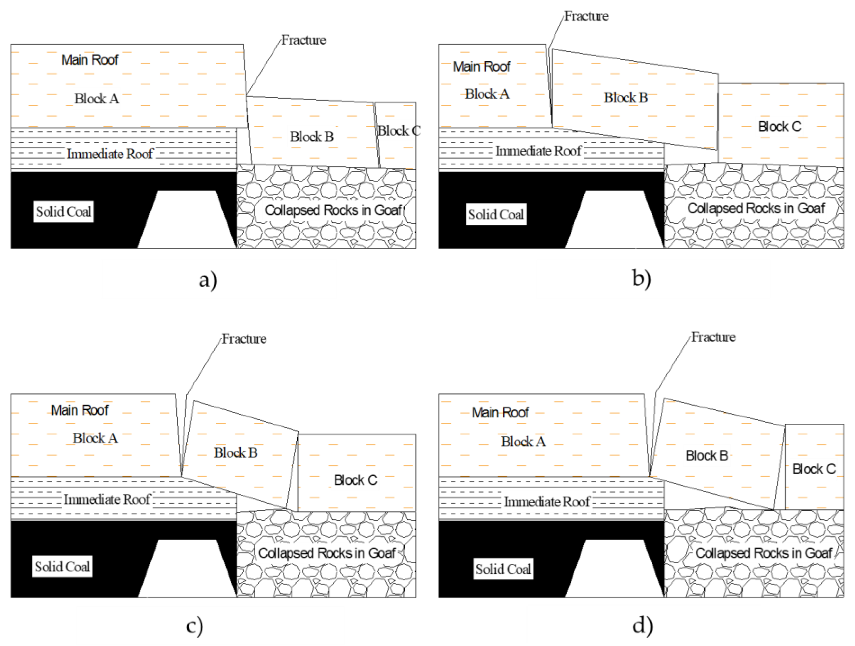
The fracture positions of the main roof can be roughly divided into four cases [22]:
(1) When the fracture position of the main roof is on the goaf side (Figure 2a), it is the most favorable situation for the stability of the surrounding rock of the gob-side entry retaining among the four fracture position cases. When the main roof fractures on the goaf side, it is relatively easy to form a stable roof structure, reducing the influence of the overlying strata movement caused by the roof rotation on the roadway.
(2) When the main roof fractures above the coal wall (Figure 2b), in this fracture situation, the main roof will inevitably have a secondary fracture on the goaf side. The surrounding rock of the gob-side roadway will bear an increased load due to the collapse of the overlying strata. However, as the broken blocks of the main roof rotate and sink until they touch the waste rock, a relatively stable voussoir beam structure will be formed. The deformation of the surrounding rock is large in the early stage, and in the later stage, the equilibrium structure formed by the collapse of the overlying strata is beneficial to the stability of the surrounding rock of the gob-side roadway to a certain extent.
(3) When the fracture position of the main roof is above the gob-side roadway (Figure 2c), this fracture situation will have an extremely adverse impact on the stability of the surrounding rock of the gob-side entry retaining. It will make the integrity of the roadway roof easily damaged, and also make the surrounding rock of the roadway easily unstable under the superimposed load of the arc-shaped triangular block B and the caving zone.
(4) When the fracture position is close to the goaf side (Figure 2d), it may cause the roadside support body on the right side of the roadway to crack. The static load of the separated block above the gob-side roadway and the dynamic load of the roof on the goaf side will disturb the roadside support body and cause stress concentration.

3.2. The Influence of Coal Seam Thickness on Main Roof Fracture

The special characteristics of three-soft coal seams (low coal strength and weak roof and floor) exacerbate the influence of coal seam thickness on the fracture location of the main roof. The influence of coal seam thickness on the main roof fracture location shows the following patterns:
(1) Thin coal seams (3–4 m)
The fracture location of the main roof is at the edge of the goaf or slightly toward the solid coal side, forming a “goaf-side fracture” pattern (Figure 2a). When the coal seam is thin, the suspended length of the main roof is short. The load is evenly transferred to the goaf gangue through the immediate roof. Fracture is likely to occur at the edge of the goaf, forming a stable articulated structure, which is beneficial for gob-side entry retaining.
(2) Medium-thick coal seams (5–7 m)
Compared with thin coal seams, the fracture location significantly migrates toward the solid coal side, changing to a “solid coal rib-side fracture” pattern (Figure 2b). The increase in coal seam thickness leads to an increase in the suspended load of the main roof, causing stress concentration on the solid coal side. When the coal seam strength is insufficient to provide support, the fracture location shifts deeper. At this time, after the main roof fractures, it is prone to form a “cantilever beam” structure. There is a large deformation of the surrounding rock in the initial stage, and it relies on gangue filling for stabilization in the later stage.
(3) Critical thickness
When the coal seam thickness is ≤4 m, the fracture location is on the goaf side or at its edge, meeting the “favorable fracture conditions” for gob-side entry retaining. When the thickness is >4 m, the fracture location moves into the solid coal side, the stability of the surrounding rock decreases significantly, and the difficulty of gob-side entry retaining increases.

4. Theoretical Analysis of Roof Influence on Underlying Coal and Rock Strata After Coal Seam Mining

4.1. Analysis of the Mechanical Model

4.1.1. Basic Assumptions

After the No. 2-1 coal seam is mined, the direct roof caves in immediately, and the main roof above the goaf is in a suspended state. The suspended main roof is in a clamped state between the overlying and underlying strata. The stiffness of the overlying and underlying strata of the main roof is less than that of the main roof. Therefore, assuming that the main roof is clamped by the elastic strata above and below, an elastic foundation boundary model can be constructed, and the following assumptions are made:
(1) Since the length of the suspended area of the main roof along the working face direction is greater than 13 times the thickness of the main roof, it can be assumed to be a beam along the working face direction with a width of 1 m.
(2) The overlying and underlying strata of the main roof are elastic foundations, and the main roof is an elastic foundation beam. The overlying and underlying strata satisfy the Winkler elastic foundation assumption.
(3) The interface between the main roof and the elastic foundation has coordinated deformation and no shear dislocation.

4.1.2. Establishment and Solution of the Mechanical Model

According to the mining and geological conditions of the 22,031 working face of XinDeng Coal Mine, in order to facilitate the calculation, the load above the main roof is simplified as a uniform load, and the influence of the plastic failure of the underlying strata on the elastic foundation parameters is ignored. Selecting the section at a certain distance behind the working face as the research object, a mechanical model of the action of the roof on the underlying coal and rock strata after coal seam mining is established, as shown in Figure 3. In the figure, q is the load on the overlying strata of the main roof; k is the Winkler elastic foundation coefficient; and h j is the thickness of the main roof. L is the suspended length of the main roof along the working face direction.
(1) Differential equation of main roof deflection
For the main roof above the goaf, the differential equation of roof deflection is:
d 4 ω ( x ) d x 4 = 12 q ( 1 ν j 2 ) E j h j 3
In the equation: ω ( x ) is the deflection of the main roof; E j is the elastic modulus of the main roof rock layer; and ν j is the Poisson’s ratio of the main roof rock layer.
For the main roof on both sides of the goaf, the differential equation of roof deflection is:
d 4 ω ( x ) d x 4 + 12 k ( 1 v j 2 ) E j h j 3 = 12 q ( 1 v j 2 ) E j h j 3
In the equation: k = ( E z h z + E c h c ) / ( h z + h c ) 2 , E z and E c are the elastic moduli of the direct roof and the coal seam, respectively; and h z and h c are the thicknesses of the direct roof and the coal seam, respectively.
(2) Model boundary conditions
At an infinite distance from the goaf, the main roof is in a clamped state between the overlying and underlying strata, and the deflection and rotation angle of the main roof are always zero. The deflection, rotation angle, bending moment, and shear force of the main roof at the boundary of the goaf are continuous.
Next, the model is solved. The model shown in Figure 2 is axisymmetric about the o-z axis, and only the left side of the main roof deflection equation needs to be solved. The general solutions of Equations (1) and (2) are obtained as follows:
ω 1 ( x ) = q x 4 ( 1 v j 2 ) 2 E j h j 3 + A 1 x 3 6 + A 2 x 2 2 + A 3 x + A 4
ω 2 ( x ) = e α x ( A 5 sin ( α x ) + A 6 cos ( α x ) ) + e α x ( A 7 sin ( α x ) + A 8 cos ( α x ) )
In the equation: A 1 ~ A 8 are unknown coefficients; α = 3 k ( 1 ν j 2 ) / E j h j 3 4 .
According to the boundary conditions of the model, there are the following equations:
{ ω 2 ( x ) | x = 0 ω 2 ( x ) | x = 0
{ ω 1 ( L 2 ) = ω 2 ( L 2 ) ω 1 ( L 2 ) = ω 2 ( L 2 ) ω 1 ( L 2 ) = ω 2 ( L 2 ) ω 1 ( L 2 ) = ω 2 ( L 2 )
The rotation angle and shear force at the midline of the model are zero, so there are the following equations:
{ ω 1 ( 0 ) = 0 ω 1 ( 0 ) = 0
Combining Equations (3) and (7), the unknowns A 1 and A 3 are solved to be zero, so Equation (3) becomes:
ω 1 ( x ) = q x 4 2 E j h j 3 + A 2 x 2 2 + A 4
Combining Equations (4) and (5), the unknowns A 5 and A 6 are solved to be zero, so Equation (4) becomes:
ω 2 ( x ) = e α x ( A 7 sin ( α x ) + A 8 cos ( α x ) )
Combining Equations (6), (8), and (9), A 2 , A 4 , A 7 , and A 8 are solved as follows:
A 2 = q L ( 12 L k D 4 + 2 ( L 2 k D + 24 ) ) 24 D ( 2 L k D + 4 k D 4 )
A 4 = 2 q L ( k L 4 k D 4 + 80 D L 2 ( k D ) 3 4 + 10 2 k L 3 + 192 2 L D k D + 384 D k D 4 ) 384 D k ( 2 L k D 4 + 4 )
A 7 = 2 q L e 2 L k D 4 4 ( ( L 2 k D + 6 2 L k D 4 + 12 ) sin 2 L k D 4 4 + ( L 2 k D + 12 ) cos 2 L k D 4 4 ) 12 ( k D ) 3 4 D ( 2 L k D 4 + 4 )
A 8 = 2 q L e 2 L k D 4 4 ( ( L 2 k D + 6 2 L k D 4 + 12 ) cos 2 L k D 4 4 + ( L 2 k D 12 ) sin 2 L k D 4 4 ) 12 ( k D ) 3 4 D ( 2 L k D 4 + 4 )
In the equation: D = E j h j 3 / 12 .
Based on the Winkler elastic foundation hypothesis, the expression for the compressive stress exerted by the main roof on the underlying coal and rock strata can be derived as follows:
p = k a × ω 2 ( x )

4.2. Fracture Laws of Overburden Roof

4.2.1. The Acting Force of the Main Roof on the Underlying Coal and Rock Strata

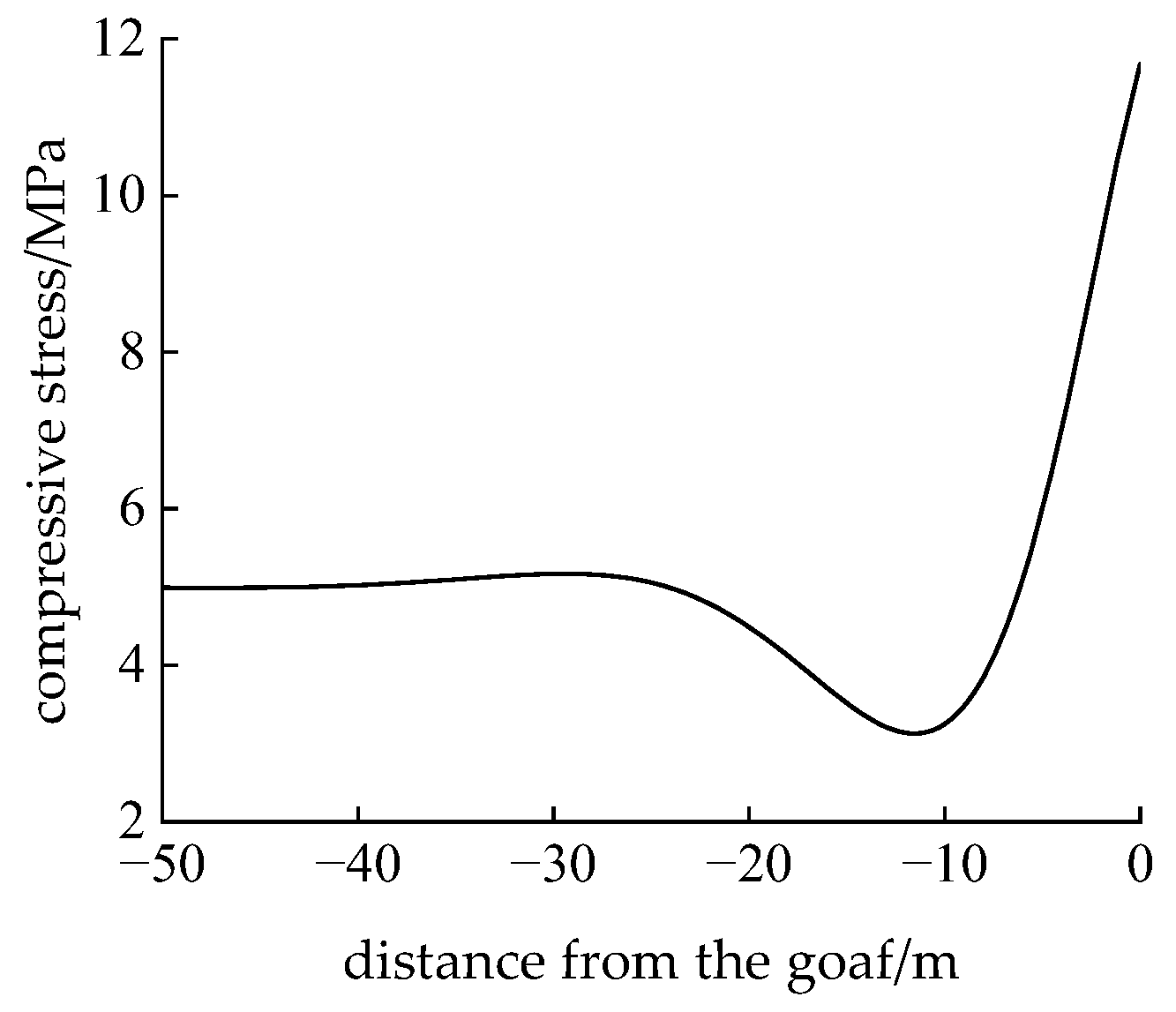
Substituting the geological and mining conditions of the 22,031 working face in Xindeng Coal Industry into Equation (14) yielded the compressive stress curve of the main roof on the underlying coal and rock strata, as shown in Figure 4. The figure indicates that after mining the No. 2-1 coal seam, the main roof transfers its overlying load to the immediate roof and coal seam on both sides of the goaf, causing stress concentration in the immediate roof and coal seam. Assuming the coal seam behaves as an elastic body, the maximum stress reaches 11.68 MPa, decreasing gradually toward the deep coal mass and returning to the initial rock stress at approximately 6.2 m depth.

4.2.2. Analysis of Roof Fracture Characteristics

Typically, the failure position of the main roof occurs at the locations with maximum bending moments, namely, the upper and lower surfaces of the main roof. This is because transverse stress reaches its peak at these positions, exceeding the tensile strength of rock-like materials and leading to failure. Thus, the relationship between the bending moment and fracture position of the main roof can be summarized as follows: the position with the maximum bending moment generally corresponds to the fracture position of the main roof. Analyzing the bending moment distribution of the main roof can help predict its failure location, thereby enabling rational support design [23,24].
The calculation formula of the bending moment of the main roof is as follows:
M = E j h j 3 12 ω 2 ( x )
Substituting the geological and mining conditions of the 22,031 working face of XinDeng (Zhengzhou, China) Coal Mine into Equation (15), the bending moment curve of the main roof is obtained as shown in Figure 5. It can be seen from the figure that after the No. 2-1 coal seam is mined, under the action of the overlying strata load and the support of the underlying coal and rock strata, bending tensile stress appears in the main roof. The position with the largest bending moment is near the goaf, about 0.5 m away from the edge of the goaf, indicating that if the main roof fractures, the fracture position is about 0.5 m away from the edge of the goaf.
(1) Coal seam thicknesses were set to 3 m, 4 m, 5 m, 6 m, and 7 m, with other conditions held constant. The compressive stress distribution curves of the main roof on underlying coal and rock strata under different seam thicknesses and the variation curves of maximum compressive stress with seam thickness are shown in Figure 6. Additionally, the bending moment curves of the main roof and the variation curves of maximum bending moment with seam thickness are presented in Figure 7. The figures indicate that the maximum compressive stress of the main roof on the underlying strata occurs at the goaf edge. The maximum compressive stress decreases exponentially with increasing seam thickness: when the seam thickness increases from 3 m to 5 m, the maximum compressive stress decreases by 1.2 MPa; when increasing from 5 m to 7 m, the reduction is 0.3 Mpa. The position of maximum bending moment in the main roof is close to the goaf edge. The maximum bending moment decreases linearly with increasing seam thickness: when the seam thickness increases from 3 m to 7 m, the maximum bending moment decreases by 66.6 MN · m.
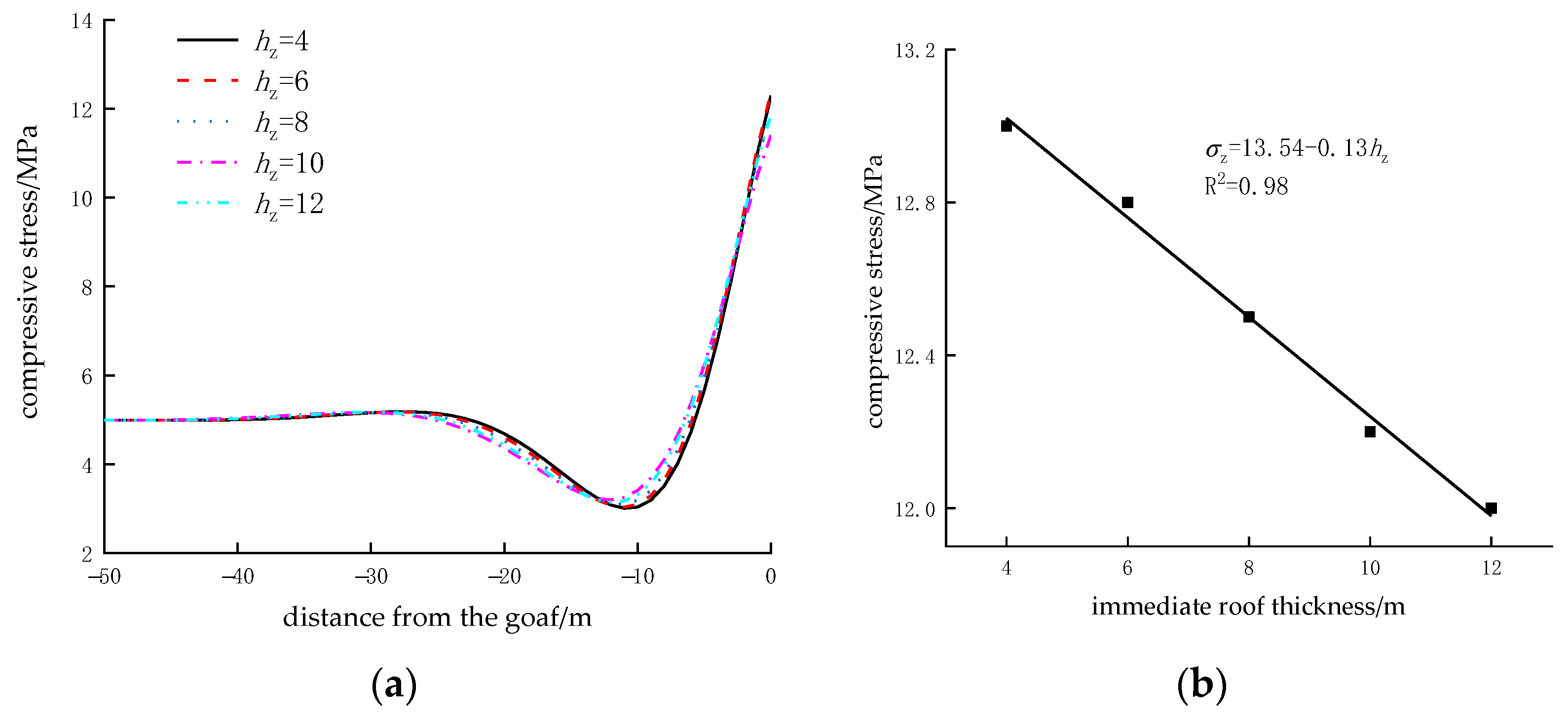
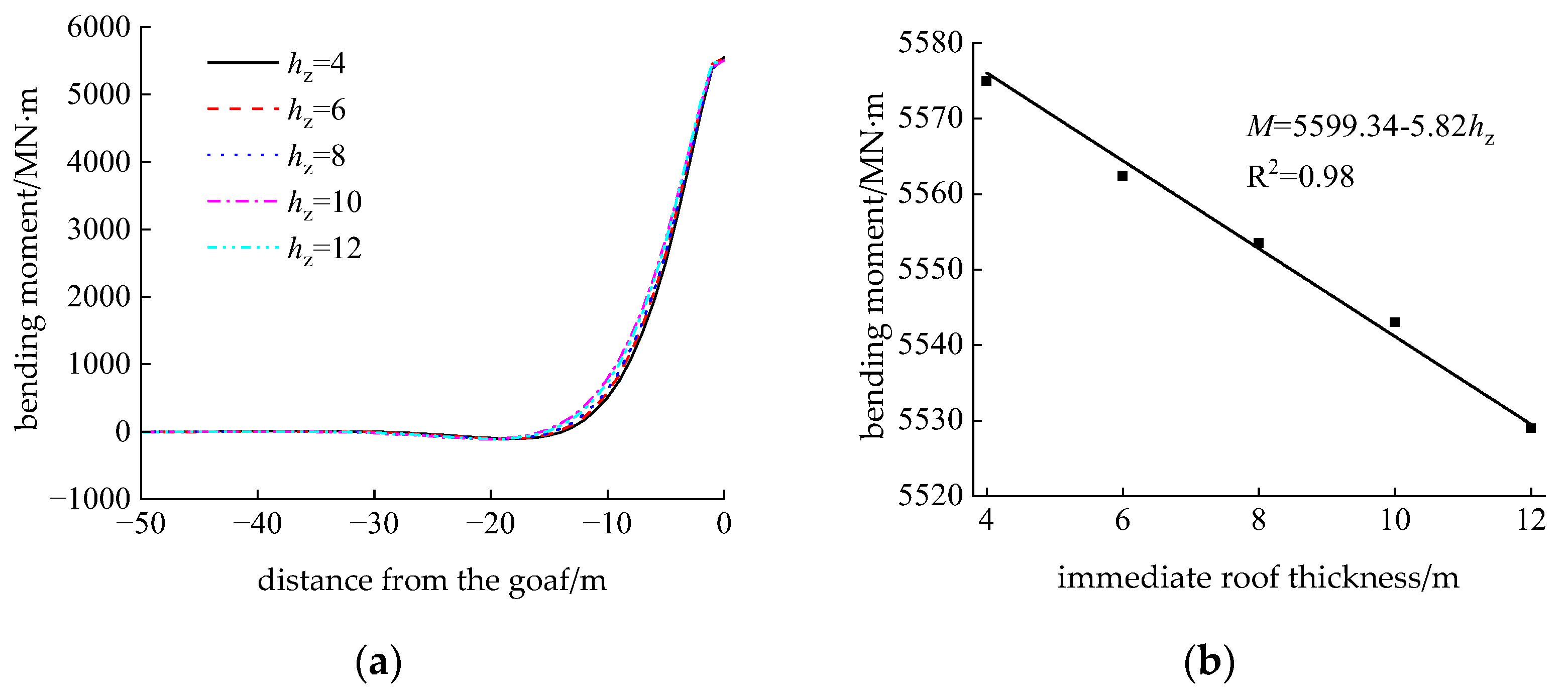
(2) Immediate roof thicknesses were set to 4 m, 6 m, 8 m, 10 m, and 12 m, with other conditions held constant. The compressive stress distribution curves of the main roof on underlying coal and rock strata under different immediate roof thicknesses and the variation curves of maximum compressive stress with immediate roof thickness are shown in Figure 8. Additionally, the bending moment curves of the main roof and the variation curves of maximum bending moment with immediate roof thickness are presented in Figure 9. The figures indicate that the maximum compressive stress of the main roof on the underlying strata occurs at the goaf edge. The maximum compressive stress decreases linearly with increasing immediate roof thickness: when the immediate roof thickness increases from 4 m to 12 m, the maximum compressive stress decreases by 1 MPa. The position of maximum bending moment in the main roof is close to the goaf edge. The maximum bending moment decreases linearly with increasing immediate roof thickness: when the immediate roof thickness increases from 4 m to 12 m, the maximum bending moment decreases by 46 MN · m.
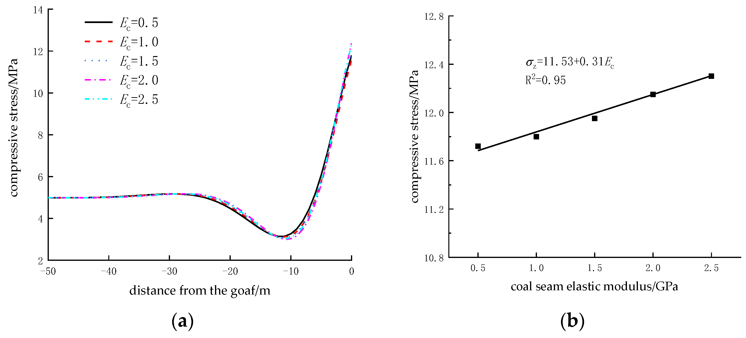
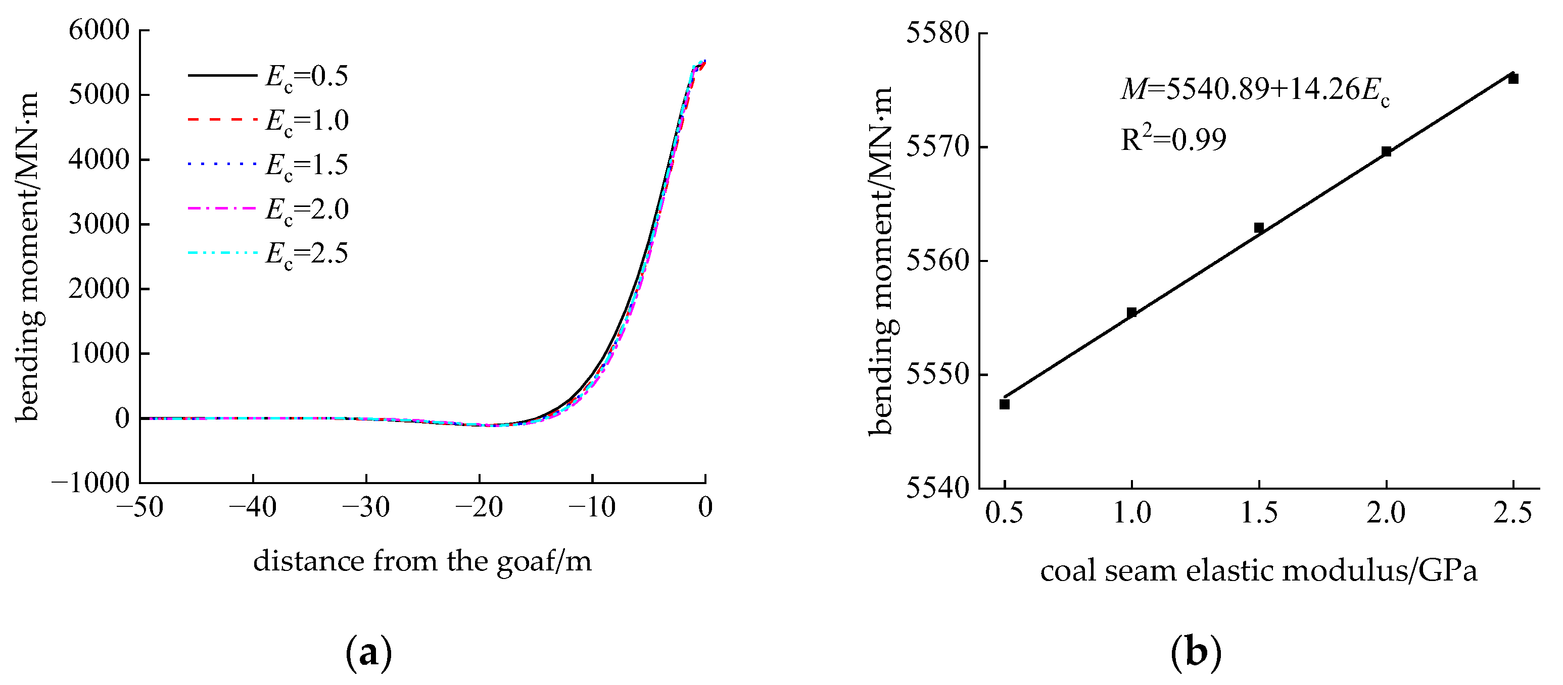
(3) Coal seam elastic moduli were set to 0.5 × 10³ MPa, 1 × 10³ MPa, 1.5 × 10³ MPa, 2 × 10³ MPa, and 2.5 × 10³ MPa, with other conditions held constant. The compressive stress distribution curves of the main roof on underlying coal and rock strata under different coal seam elastic moduli and the variation curves of maximum compressive stress with elastic modulus are shown in Figure 10. Additionally, the bending moment curves of the main roof and the variation curves of maximum bending moment with elastic modulus are presented in Figure 11. The figures indicate that the maximum compressive stress of the main roof on the underlying strata occurs at the goaf edge. The maximum compressive stress increases linearly with increasing coal seam elastic modulus: when the elastic modulus increases from 0.5 × 10³ MPa to 2.5 × 10³ MPa, the maximum compressive stress increases by 0.62 MPa. The position of maximum bending moment in the main roof is close to the goaf edge. The maximum bending moment increases linearly with increasing coal seam elastic modulus: when the elastic modulus increases from 0.5 × 10³ MPa to ×103 MPa, the maximum bending moment increases by 28.6 MN · m.
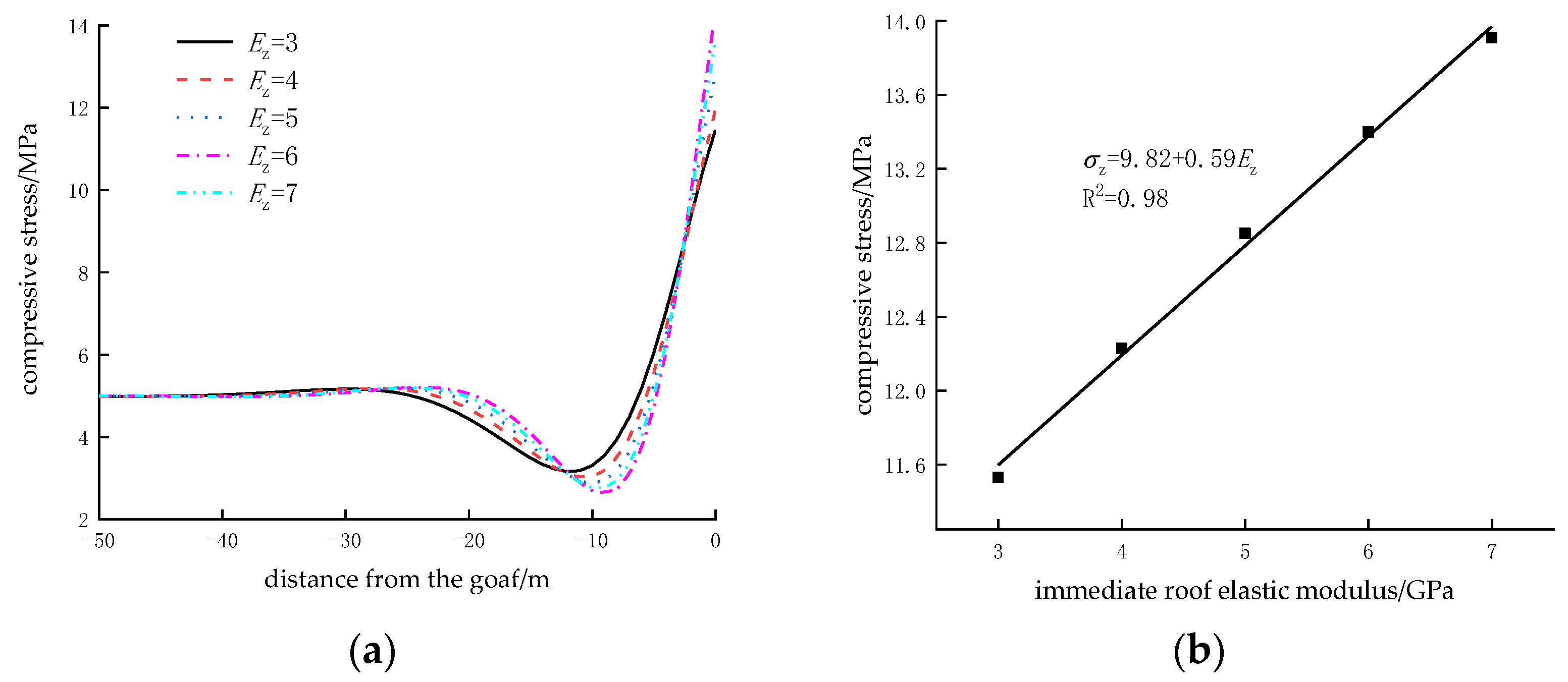
(4) Immediate roof elastic moduli were set to 3 × 10³ MPa, 4 × 10³ MPa, 5 × 10³ MPa, 6 × 10³ MPa, and 7 × 10³ MPa, with other conditions held constant. The compressive stress distribution curves of the main roof on underlying coal and rock strata under different immediate roof elastic moduli and the variation curves of maximum compressive stress with elastic modulus are shown in Figure 12. Additionally, the bending moment curves of the main roof and the variation curves of maximum bending moment with elastic modulus are presented in Figure 13. The figures indicate that the maximum compressive stress of the main roof on the underlying strata occurs at the goaf edge. The maximum compressive stress increases linearly with increasing immediate roof elastic modulus: when the elastic modulus increases from 3 × 10³ MPa to 7 × 10³ MPa, the maximum compressive stress increases by 2.38 MPa. The position of maximum bending moment in the main roof is close to the goaf edge. The maximum bending moment increases logarithmically with increasing immediate roof elastic modulus: when the elastic modulus increases from 3 × 10³ MPa to 5 × 10³ MPa, the maximum bending moment increases by 57.7 MN· m; when increasing from 5 × 10³ MPa to 7 × 10³ MPa, the increase is 34.1 MN · m.
In summary, the quantitative study on factors influencing roof stability during coal seam mining using the range analysis method shows that the immediate roof elastic modulus (range 2.38/91.8) is the most critical parameter affecting maximum compressive stress and maximum bending moment. As the immediate roof elastic modulus varies from 3 × 10³ MPa to 7 × 10³ MPa, the corresponding maximum compressive stress ranges from 11.46 MPa to 13.84 MPa, and the maximum bending moment ranges from 5491.1 MN· m to 5582.9 MN· m, with ranges reaching 2.38 and 91.8, respectively. As the coal seam thickness varies from 3 m to 7 m, the corresponding maximum compressive stress ranges from 10.84 MPa to 12.30 MPa, and the maximum bending moment ranges from 5377.2 MN· m to 5443.8 MN· m. As the immediate roof thickness varies from 4 m to 12 m, the corresponding maximum compressive stress ranges from 11.28 MPa to 12.28 MPa, and the maximum bending moment ranges from 5506 MN· m to 5552 MN· m. Coal seam thickness (range 1.46/66.6) and immediate roof thickness (range 1/46) follow in significance, while the coal seam elastic modulus varies from 0.5 × 10³ MPa to 2.5 × 10³ MPa, the corresponding maximum compressive stress ranges from 11.79 MPa to 12.41 MPa, and the maximum bending moment ranges from 5494 MN· m to 5522.6 MN· m, with coal seam elastic modulus (range 0.62/28.6) having the least impact. The maximum compressive stress decreases exponentially with increasing coal seam thickness and linearly with increasing immediate roof thickness, while increasing linearly with coal seam and immediate roof elastic moduli. The maximum bending moment decreases linearly with increasing coal seam and immediate roof thicknesses, while increasing linearly with coal seam elastic modulus and logarithmically with immediate roof elastic modulus. Comprehensive mechanical response characteristics reveal that a stress concentration sensitive zone exists within 0.3–0.6 m of the goaf edge in the main roof, where primary failure is most likely to occur.

4.3. The Effect of Horizontal Stress on Roadway Stability

The above analysis primarily focuses on the influence of vertical stress on roadways. However, under the geological conditions of shallow-buried “three-soft” coal seams, horizontal stress also affects roadway stability to a certain extent. Restricted by two factors—shallow burial depth (vertical height of 120–150 m) and the mechanical properties of soft coal and rock (coal mass firmness coefficient f = 0.13–0.17, classified as Class III–IV fractured coal mass)—the magnitude of horizontal stress is relatively low, typically less than 20% of vertical stress. Its influence on roadway stability is manifested in the following aspects:
(1) Dominant role in sidewall deformation
Horizontal stress primarily induces shear failure and plastic flow in the coal mass of the roadway sidewalls. When horizontal stress exceeds the shear strength of the coal mass, sidewall displacement increases compared to conditions without horizontal stress, prone to sidewall spalling, and failure of the support structure.
(2) Auxiliary role in roof fracture
Although horizontal stress does not directly dominate the fracture of the main roof (which is driven by vertical bending moments), the lateral deformation of the coal mass induced by horizontal stress alters the boundary constraints of the main roof.
(3) Coupling effect with vertical stress
In local areas where the ratio of horizontal-to-vertical stress is relatively high, the roadway roof is prone to combined tension–shear failure, forming an “X”-shaped fracture network that significantly reduces the self-stabilizing capacity of the surrounding rock.
Overall, in shallow-buried “three-soft” coal seams, horizontal stress primarily triggers sidewall instability, but the overall control factor for roadway stability remains the vertical stress-dominated fracture of the main roof. In the design of gob-side entry retaining, reinforcement measures for sidewall deformation induced by horizontal stress should be adopted to complement roof fracture control techniques and ensure the stability of gob-side entry retaining.

5. Numerical Simulation of Stope Overburden

5.1. Numerical Model Development

Based on the comprehensive stratigraphic column and geological borehole column of Xindeng (Zhengzhou, China) Coal Industry, combined with mining deployment plans, a particle flow model for overburden movement during mining of the 22,031 working face was established along the inclined length direction of the face, with dimensions of length × height = 130 m × 123.8 m (Figure 14). The face end distance from the model’s left boundary was set to 70 m. Horizontal lateral displacement was restrained at the left and right boundaries, fixed support conditions were applied at the bottom, and a uniform load of 2.7 MPa (simulating a 104.2 m overburden) was applied at the top. During the mining simulation of the working face, the No. 2-1 coal seam was extracted in 5 m increments. Physical and mechanical parameters of each rock stratum are referred to in Table 1. The model employs the particle flow discrete element software PFC2D (Particle Flow Code), chosen for its suitability in simulating fracture propagation in jointed rock masses and contact mechanical behavior between particles—features that align with the geological characteristics of the three-soft coal seam roof, which is fragmented and highly jointed. In this research work, a parallel bond model was adopted. The fracture failure and mechanical transmission of rock strata were described through the meso-scale bonding effect between particles. The model did not consider the support measures and only simulated the migration and caving process of overburden strata in the natural state, focusing on the analysis of the dynamic response of rock strata under unsupported conditions.

5.2. Post-Mining Roof Fracture Characteristics of Gob-Side Entry Retaining for No. 2-1 Coal Seam

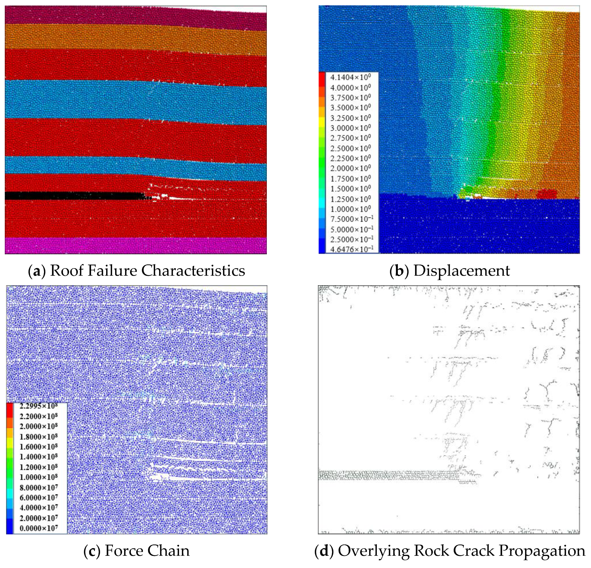
The fracture positions and patterns of the roof after mining the No. 2-1 coal seam are shown in Figure 15. After mining the No. 2-1 coal seam, the immediate roof and main roof first fractured at the goaf edge above the No. 2-1 coal seam. Under continuous roof pressure, cracks emerged in the immediate roof at 0 m and 4.8 m from the goaf edge, and in the main roof at 0 m and 6.2 m from the goaf edge. These cracks developed obliquely with dip angles facing the goaf and penetrated both the immediate roof and main roof. Although cracks also formed in the overlying strata of the main roof, they did not fully penetrate the rock layers. As a result, force transmission within the strata was maintained, forming a relatively stable structure that benefits the application of gob-side entry retaining technology.

5.2.1. Influence of Coal Seam Thickness

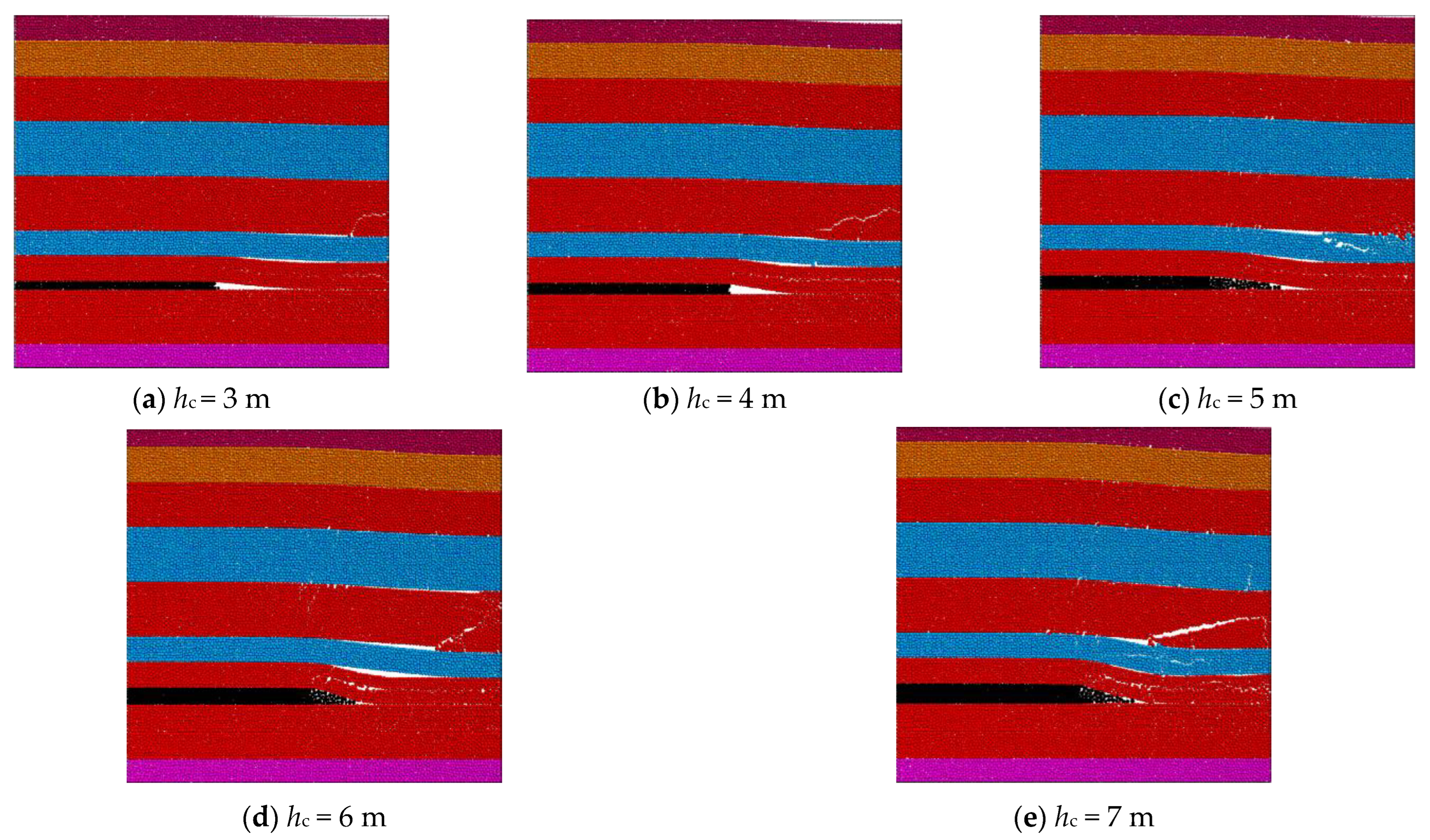
The roof fracture characteristics under different coal seam thicknesses are shown in Figure 16, and the statistical results of the main roof fracture positions are presented in Table 2. In the table, “+” indicates the main roof fracture position above the goaf, while “-” indicates the position above the solid coal. The table and figure reveal that as coal seam thickness increases, when the coal seam thickness increases from 3 m to 7 m, the fracture location migrates 8.2 m toward the solid coal side (from +0.5 m to −7.7 m, Table 2), and the main roof fracture position exhibits a clear trend of shifting toward the solid coal side. This indicates that when coal seam thickness increases, the fracture position of the main roof generally moves deeper into the coal seam. Considering the influence of the main roof’s lateral fracture structure on the surrounding rock stability of gob-side entry retaining and the degree of coal seam yielding, it is evident that under coal seam thicknesses of 3 m and 4 m, the surrounding rock of gob-side entry retaining can generally maintain stability. However, under thicknesses of 5 m to 7 m, maintaining stability becomes significantly more challenging.

5.2.2. Influence of Immediate Roof Thickness

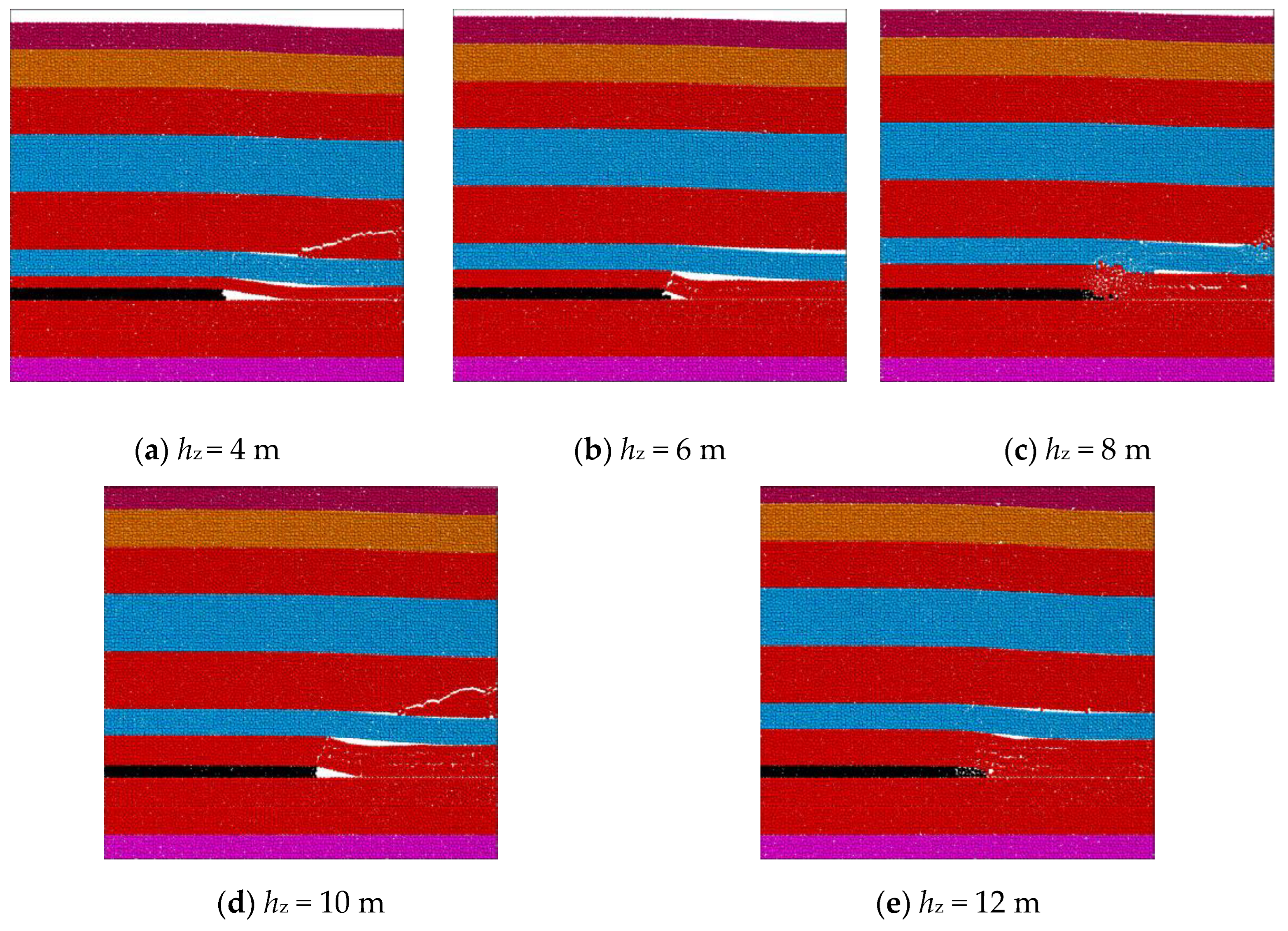
Roof fracture characteristics under different immediate roof thicknesses are shown in Figure 17, and the statistical results of the main roof fracture positions are presented in Table 3. The table and figure indicate that as immediate roof thickness increases, when the immediate roof thickness increases from 4 m to 12 m, the fracture location migrates 4.9 m toward the solid coal side (from +1.4 m to −3.5 m, Table 3), and the main roof fracture position exhibits a clear trend of shifting toward the solid coal side. This suggests that when immediate roof thickness increases, the fracture position of the main roof generally moves deeper into the coal seam. Considering the influence of the main roof’s lateral fracture structure on the surrounding rock stability of gob-side entry retaining and the degree of coal seam yielding, it is evident that under immediate roof thicknesses of 4 m to 8 m, the surrounding rock of gob-side entry retaining can generally maintain stability. However, under thicknesses of 10 m and 12 m, maintaining stability becomes significantly more challenging.

5.2.3. Influence of Coal Seam Elastic Modulus

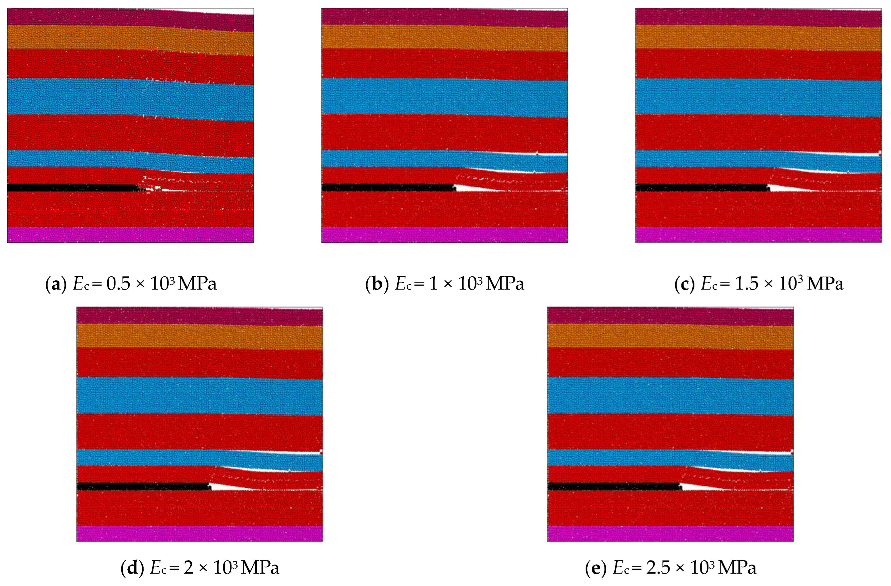
Roof fracture characteristics under different coal seam elastic moduli are shown in Figure 18, and the statistical results of the main roof fracture positions are presented in Table 4. The table and figure indicate that as coal seam elastic modulus increases, when the coal seam elastic modulus increases from 0.5 × 10³ MPa to 2.5 × 10³ MPa, the fracture location migrates 1.4 m toward the goaf side (from +0 m to +1.4 m, Table 4), and the main roof fracture position exhibits a clear trend of shifting toward the goaf side. This suggests that when the coal seam elastic modulus increases, the fracture position of the main roof generally moves deeper into the goaf. Considering the influence of the main roof’s lateral fracture structure on the surrounding rock stability of gob-side entry retaining and the degree of coal seam yielding, it is evident that under coal seam elastic moduli of 0.5–2.5 × 10³ MPa, the surrounding rock of gob-side entry retaining can generally maintain stability.

5.2.4. Influence of Immediate Roof Elastic Modulus

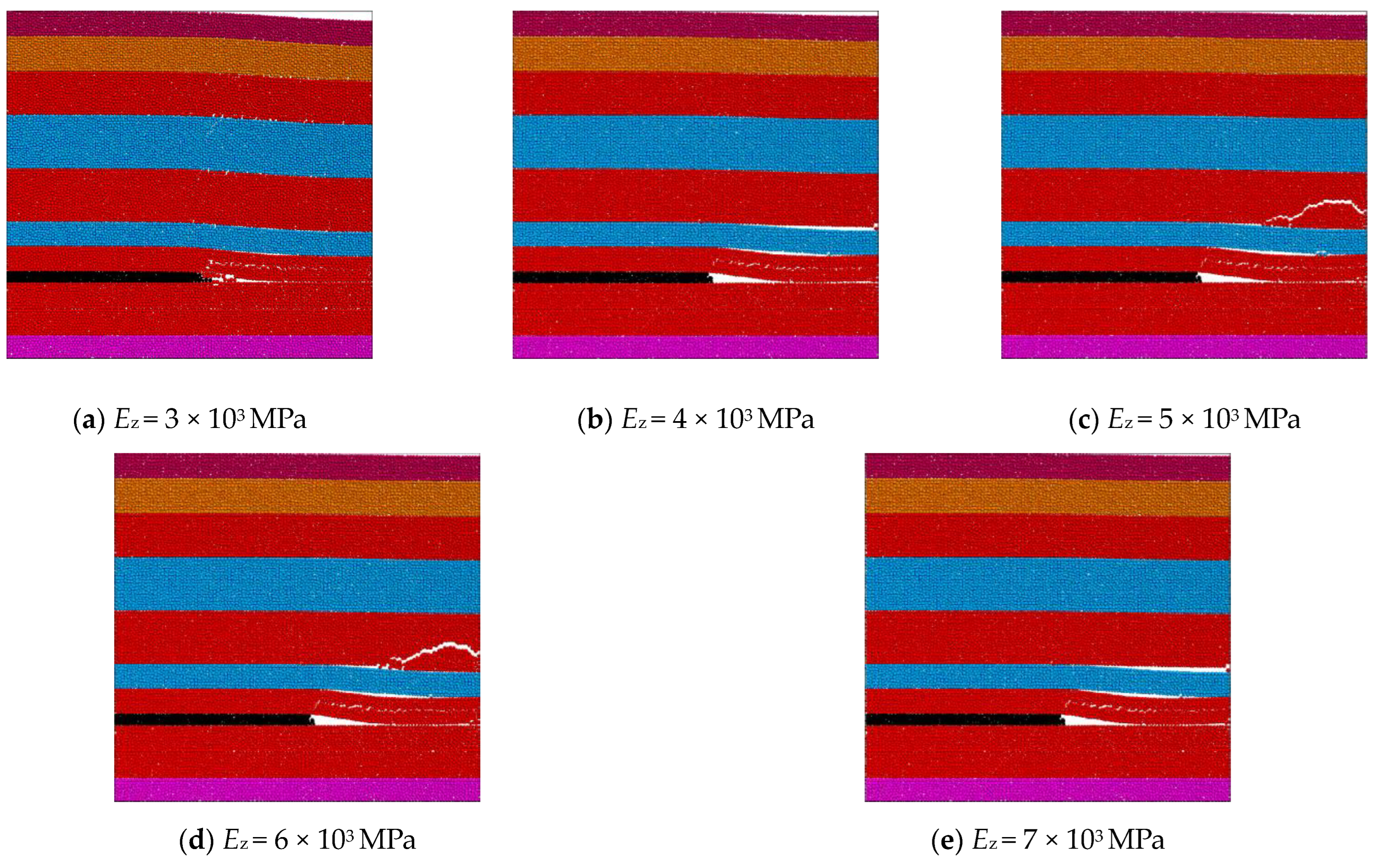
Roof fracture characteristics under different immediate roof elastic moduli are shown in Figure 19, and the statistical results of the main roof fracture positions are presented in Table 5. The table and figure indicate that as immediate roof elastic modulus increases, when the immediate roof elastic modulus increases from 3 × 10³ Mpa to 7 × 10³ Mpa, the fracture location migrates 1.5 m toward the goaf side (from +0 m to +1.5 m, Table 5), and the main roof fracture position exhibits a clear trend of shifting toward the goaf side. This suggests that when the immediate roof elastic modulus increases, the fracture position of the main roof generally moves deeper into the goaf. Considering the influence of the main roof’s lateral fracture structure on the surrounding rock stability of gob-side entry retaining and the degree of immediate roof yielding, it is evident that under immediate roof elastic moduli of 3–7 × 10³ Mpa, the surrounding rock of gob-side entry retaining can generally maintain stability.
The particle flow numerical simulation results are generally consistent with theoretical calculations regarding the initial crack position in the main roof. Specifically, the theoretical calculation indicates that the fracture position of the main roof is 0.5 m from the edge of the goaf, while the numerical simulation results range from 0 to 1.4 m (as shown in Table 2, Table 3, Table 4 and Table 5). The error range is ≤ 1.4 m, and the coincidence degree exceeds 85%, which verifies the reliability of the model. Through the simulation results, the feasibility and practicality of roof fracture characteristics after mining the No. 2-1 coal seam are analyzed. Additionally, parameter thresholds such as coal seam thickness (≤4 m) and immediate roof thickness (≤8 m) can be used to rapidly determine whether geological conditions in specific areas are suitable for gob-side entry retaining. When the immediate roof elastic modulus ranges from 3 to 7 × 10³ MPa, non-pillar mining technology should be prioritized to reduce resource waste. This study provides a reference basis for the application of gob-side entry retaining technology.

6. Conclusions

(1) Through mechanical modeling, the force exerted by the main roof of the No. 2-1 coal seam on underlying coal and rock strata and the fracture position of the main roof were analyzed. The results revealed that the maximum force applied by the main roof on underlying strata was 11.68 MPa, gradually decreasing toward the deep coal mass and reducing to in situ stress at approximately 6.2 m. The fracture position of the main roof occurred at a distance of approximately 0.5 m from the goaf edge.
(2) The influence of parameters on the maximum force exerted by the main roof on underlying coal and rock strata decreases in the following order: immediate roof elastic modulus, coal seam thickness, immediate roof thickness, and coal seam elastic modulus. The maximum compressive stress decreases exponentially with increasing coal seam thickness and linearly with increasing immediate roof thickness, while increasing linearly with coal seam and immediate roof elastic moduli.
(3) We found that the main roof is most prone to primary failure near the goaf edge at approximately 0.3–0.6 m. The influence of parameters on maximum bending moment decreases in the following order: immediate roof elastic modulus, coal seam thickness, immediate roof thickness, and coal seam elastic modulus. The maximum bending moment decreases linearly with increasing coal seam and immediate roof thicknesses, while increasing linearly with coal seam elastic modulus and logarithmically with immediate roof elastic modulus.
(4) Under coal seam thicknesses of 3 m and 4 m, the surrounding rock of gob-side entry retaining can generally maintain stability. However, under thicknesses of 5 m to 7 m, maintaining stability becomes significantly more challenging. Similarly, under immediate roof thicknesses of 4 m to 8 m, stability is generally achievable, whereas under thicknesses of 10 m and 12 m, stability is difficult to maintain. Additionally, when coal seam elastic modulus ranges from 0.5 to 2.5 × 10³ MPa and immediate roof elastic modulus ranges from 3 to 7 × 10³ MPa, the surrounding rock of gob-side entry retaining can generally remain stable.

Author Contributions

Conceptualization, G.H. and Y.Y.; methodology, G.H. and Y.Y.; software, G.H.; validation, G.H., S.L. and K.Z.; formal analysis, G.H.; investigation, G.H.; resources, Y.Y.; data curation, G.H.; writing—original draft preparation, G.H.; writing—review and editing, G.H.; visualization, G.H.; supervision, Y.Y.; project administration, Y.Y.; funding acquisition, Y.Y. All authors have read and approved the published version of the manuscript.

Funding

This work was supported by the National Natural Science Foundation of China (Grant Nos. 51404167, 42302202), the General Project of the Applied Basic Research Program of Shanxi Province (202303021211057), and the Teaching Reform and Innovation Project of Higher Education Institutions in Shanxi Province (J2019055).

Institutional Review Board Statement

Not applicable.

Informed Consent Statement

Not applicable.

Data Availability Statement

The data used to support the findings of this study are included within the article.

Conflicts of Interest

The authors declare no conflicts of interest.

References

  1. Song, Z.Q.; Cui, Z.D.; Xia, H.C.; Tang, J.Q.; Wen, Z.J. The fundamental theoretical and engineering research on the green safe no coal pillar mining model by mainly using coal gangue backfill. J. China Coal Soc. 2010, 35, 705–710. [Google Scholar] [CrossRef]
  2. He, M.; Zhu, G.; Guo, Z. Longwall mining “cutting cantilever beam theory” and 110 mining method in China: The third mining science innovation. J. Rock Mech. Geotech. Eng. 2015, 7, 483–492. [Google Scholar] [CrossRef]
  3. Zhang, Z.; Bai, J.; Wang, X.; Xu, Y.; Yan, S.; Liu, H.; Wu, W.; Zhang, W. Research Progress and Prospects of Surrounding Rock Control Technology for Gob-Side Entry Retaining in China. J. China Coal Soc. 2023, 48, 3979–4000. [Google Scholar] [CrossRef]
  4. He, M.C.; Gao, Y.B.; Yang, J.; Guo, Z.B.; Wang, E.Y.; Wang, Y.J. An energy-gathered roof cutting technique in no-pillar mining and its impact on stress variation in surrounding rocks. J. Rock Mech. Eng. 2017, 36, 1314–1325. [Google Scholar] [CrossRef]
  5. Kang, H.; Zhang, X.; Wang, D.; Tian, J.; Yi, Z.; Jiang, W. Surrounding Rock Control Technology and Its Application in Non-Pillar Mining. J. China Coal Soc. 2022, 47, 16–44. [Google Scholar] [CrossRef]
  6. Wang, Y.J.; He, M.C.; Zhang, K.X.; Yang, J.; Zhen, E.Z.; Zhu, Z.; Gao, Y.; Ma, Z.M. Strata behavior characteristics and control countermeasures for the gateroad surroundings in innovative non-pillar mining method with gateroad formed automatically. J. Min. Saf. Eng. 2018, 35, 677–685. [Google Scholar] [CrossRef]
  7. Wang, J.; Xu, J.; Yang, S.; Wang, Z. Development of strata movement and its control in underground mining: In memory of 40 years of Voussoir Beam Theory proposed by Academician Minggao Qian. Coal Sci. Technol. 2023, 51, 80–94. [Google Scholar] [CrossRef]
  8. Zhang, D.; Guo, Y.; Bai, J.; Tian, Z.; Zhang, Z.; Wang, R.; Fu, H.; Liu, S.; Deng, M.; Zhu, Q.; et al. Dynamic Stability Mechanism and Control of Surrounding Rock in Abandoned Roadways under Masonry Beam Structure. J. China Coal Soc. 2025, 1–18. [Google Scholar] [CrossRef]
  9. Zhang, W.; Cao, L.; Zhang, D.; Hu, Y.; Chang, J.; Zhang, Z. Deformation and Fracture Mechanisms of Thick Hard Roofs in Upward Mining Coalfaces: A Mechanical Model and Its Validation. Appl. Sci. 2024, 14, 10278. [Google Scholar] [CrossRef]
  10. Gao, X.; Pan, Y.; Zhao, T.; Wang, W.; Xiao, Y.; Song, Y.; Dai, L. Interlayer Shear Sliding Behaviors during the Fracture Process of Thick Sandstone Roof and Its Mechanism Leading to Coal Mine Tremors. Appl. Sci. 2024, 14, 4323. [Google Scholar] [CrossRef]
  11. Li, J.; Zheng, C.; Gu, S.; Wu, B.; Wang, X.; Song, Y. Study and Application of the Fracture Mechanics Model for Stope Roof under the Coupling Effect of Immediate Roof and Main Roof. Coal Geol. Explor. 2023, 51, 123–129. [Google Scholar]
  12. Gao, L.; Liu, P.; Zhang, P.; Wu, G.; Kang, X. Influence of fracture types of main roof on the stability of surrounding rock of the gob-side coal-rock roadway in inclined coal seams and its engineering application. Meitiandizhi Yu Kantan/Coal Geol. Explor. 2022, 50, 73–80. [Google Scholar] [CrossRef]
  13. Yang, D.; Gao, M.; Cheng, Y.; Sheng, W.; Chen, J. Analysis on instability of surrounding rock in gob-side entry retaining with the character of soft rock composite roof. Adv. Mater. Res. 2012, 524–527, 396–403. [Google Scholar] [CrossRef]
  14. Chen, D.; Wang, X.; Li, M.; Bai, J.; Zhang, F.; Yu, Y.; Zhao, X.; Wang, G. Study on the Fracture Location of Main Roof and Stability of Surrounding Rock in the Gob-Side Entry. SSRN 2023. [Google Scholar] [CrossRef]
  15. Yu, B.; Kuang, T.; Yang, J.; Zhu, W. Analysis of Overlying Strata Structure and Its Evolution Characteristics for Hard Roof in Ultra-Thick Coal Seam Mining. Coal Sci. Technol. 2023, 51, 95–104. [Google Scholar] [CrossRef]
  16. Liu, J.; Li, C.; Shi, Y.; Zhang, Y. Stability Analysis and Fracture Patterns of Hard Main Roof in Longwall Top Coal Caving with Large Mining Height. Shock. Vib. 2021, 2021, 9930221. [Google Scholar] [CrossRef]
  17. Herezy, Ł.; Janik, D.; Skrzypkowski, K. Powered Roof Support—Rock Strata Interactions on the Example of an Automated Coal Plough Syste. Stud. Geotech. Mechanica 2018, 40, 46–55. [Google Scholar] [CrossRef]
  18. Xu, G.; Zhang, C.; Lin, X.; Chi, G.M.; Fan, C.Z.; Yu, Y.J. Roof Pressure Evolution and Support Crushing Prediction of Fully Mechanized Caving Face Based on Zoning Support Mechanical Model. J. China Coal Soc. 2022, 47, 3622–3633. [Google Scholar] [CrossRef]
  19. Vu, T.T.; Do, S.A. Determination of the rock mass displacement zone by numerical modeling method when exploiting the longwall at the Nui Beo Coal Mine, Vietnam. Min. Miner. Depos. 2023, 17, 59–66. [Google Scholar] [CrossRef]
  20. Demin, V.; Khalikova, E.; Rabatuly, M.; Amanzholov, Z.; Zhumabekova, A.; Syzdykbaeva, D.; Bakhmagambetova, G.; Yelzhanov, Y. Research into mine working fastening technology in the zones of increased rock pressure behind the longwall face to ensure safe mining operations. Min. Miner. Depos. 2024, 18, 27–36. [Google Scholar] [CrossRef]
  21. Kumar, R.; Singh, A.K.; Mishra, A.K.; Singh, R. Underground mining of thick coal seams. Int. J. Min. Sci. Technol. 2015, 25, 885–896. [Google Scholar] [CrossRef]
  22. Shen, J. Study on the Mechanism of Overburden Movement and Retaining Strategies for Gob-Side Entry Retaining in Three-Soft Thick Coal Seams. Ph.D. Thesis, Henan Polytechnic University, Jiaozuo, China, 2022. [Google Scholar] [CrossRef]
  23. Wang, Z.; Fang, S.; Zhang, C. Deformation Characteristics and Response Factors of Rock Bolt Body in Roadway with Layered Composite Roof. Appl. Sci. 2024, 14, 6694. [Google Scholar] [CrossRef]
  24. Lv, K.; He, F.; Xu, X.; Zhai, W.; Qin, B. Fracture characteristics and stability analysis of the main roof structure with special—Shaped load—Elastic foundation. Chin. J. Rock Mech. Eng. 2023, 42, 930–947. [Google Scholar] [CrossRef]
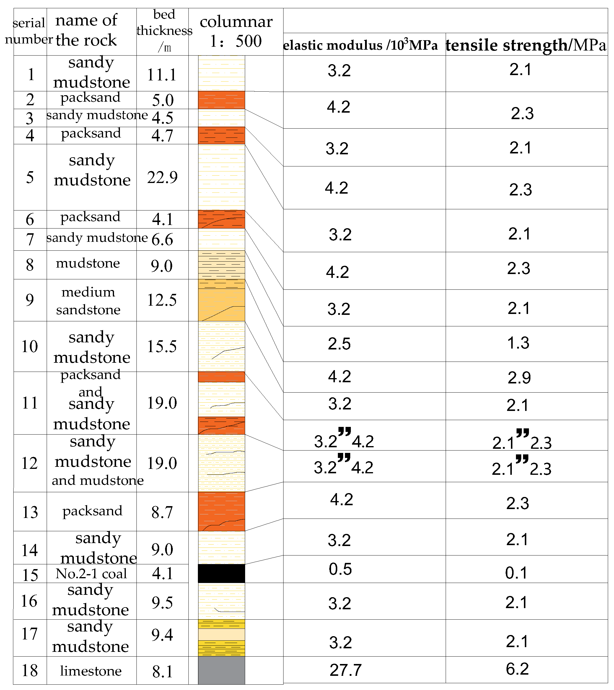
Figure 1. Integrated rock layer bar graph.
Applsci 15 04607 g001
Figure 2. Schematic Diagram of the Fracture Position of the Main Roof. (a) Fracture on the goaf side, (b) Fracture above the coal wall, (c) Fracture above the gob-side roadway and (d) Fracture close to the goaf side.
Applsci 15 04607 g002
Figure 3. Roof stress analysis diagram.
Applsci 15 04607 g003
Figure 4. Compressive Stress Curve of the Main Roof on Underlying Coal and Rock Layers.
Applsci 15 04607 g004
Figure 5. The basic top bending moment curve.
Applsci 15 04607 g005
Figure 6. Compressive Stress Distribution of the Main Roof on Underlying Coal and Rock Layers under Different Coal Seam Thickness Conditions: (a) Variation in Compressive Stress with Distance from Goaf; (b) Variation in Maximum Compressive Stress with Coal Seam Thickness.
Applsci 15 04607 g006
Figure 7. Bending Moment Distribution of the Main Roof under Different Coal Seam Thickness Conditions: (a) Variation in Bending Moment with Distance from Goaf; (b) Variation in Maximum Bending Moment with Coal Seam Thickness.
Applsci 15 04607 g007
Figure 8. Compressive Stress Distribution of the Main Roof on Underlying Coal and Rock Layers under Different Immediate Roof Thickness Conditions: (a) Variation in Compressive Stress with Distance from Goaf; (b) Variation in Maximum Compressive Stress with Immediate Roof Thickness.
Applsci 15 04607 g008
Figure 9. Bending Moment Distribution of the Main Roof under Different Immediate Roof Thickness Conditions: (a) Variation in Bending Moment with Distance from Goaf; (b) Variation in Maximum Bending Moment with Immediate Roof Thickness.
Applsci 15 04607 g009
Figure 10. Compressive Stress Distribution of the Main Roof on Underlying Coal and Rock Layers under Different Coal Seam Elastic Modulus Conditions: (a) Variation in Compressive Stress with Distance from Goaf; (b) Variation in Maximum Compressive Stress with Coal Seam Elastic Modulus.
Applsci 15 04607 g010
Figure 11. Bending Moment Distribution of the Main Roof under Different Coal Seam Elastic Modulus Conditions: (a) Variation in Bending Moment with Distance from Goaf; (b) Variation in Maximum Bending Moment with Coal Seam Elastic Modulus.
Applsci 15 04607 g011
Figure 12. Compressive Stress Distribution of the Main Roof on Underlying Coal and Rock Layers under Different Immediate Roof Elastic Modulus Conditions: (a) Variation in Compressive Stress with Distance from Goaf; (b) Variation in Maximum Compressive Stress with Immediate Roof Elastic Modulus.
Applsci 15 04607 g012
Figure 13. Bending Moment Distribution of the Main Roof under Different Immediate Roof Elastic Modulus Conditions: (a) Variation in Bending Moment with Distance from Goaf; (b) Variation in Maximum Bending Moment with Immediate Roof Elastic Modulus.
Applsci 15 04607 g013
Figure 14. Particle Flow Model for Mined Overburden Transport.
Applsci 15 04607 g014
Figure 15. Roof Failure Location and Pattern after Mining of Coal Seam 2-1.
Applsci 15 04607 g015
Figure 16. Roof Failure Characteristics under Different Coal Seam Thickness Conditions.
Applsci 15 04607 g016
Figure 17. Roof Failure Characteristics under Different Immediate Roof Thickness Conditions.
Applsci 15 04607 g017
Figure 18. Roof Failure Characteristics under Different Coal Seam Elastic Modulus Conditions.
Applsci 15 04607 g018
Figure 19. Roof Failure Characteristics under Different Immediate Roof Elastic Modulus Conditions.
Applsci 15 04607 g019
Table 1. Mechanical parameters of overburden rock.
LithologyElastic Modulus /103 MPaTensile
Strength
/MPa
Cohesion
/MPa
Internal Friction Angle
Poisson Ratio
sandy mudstone3.22.13.5250.31
packsand4.22.34.4220.24
mudstone2.51.32.2240.17
medium sandstone4.22.95.9260.27
No. 2-1 coal0.50.11.5220.24
limestone27.76.245.812.60.3
Table 2. Failure Locations of the Main Roof under Different Coal Seam Thickness Conditions.
Coal Seam Thickness/m34567
Fracture Position/m+0.50−0.4−4.5−7.7
Table 3. Fracture Locations of the Main Roof under Different Immediate Roof Thickness Conditions.
Immediate Roof Thickness/m4681012
Fracture Position/m+1.4+0.50−1.5−3.5
Table 4. Failure Locations of the Main Roof under Different Coal Seam Elastic Modulus Conditions.
Coal Seam Elastic Modulus/
103 MPa
0.511.522.5
Fracture Position/m00+1.4+1.4+1.4
Table 5. Failure Locations of the Main Roof under Different Immediate Roof Elastic Modulus Conditions.
Immediate Roof Elastic Modulus/103 MPa34567
Fracture Position /m0+1.4+1.4+1.5+1.5
Disclaimer/Publisher’s Note: The statements, opinions and data contained in all publications are solely those of the individual author(s) and contributor(s) and not of MDPI and/or the editor(s). MDPI and/or the editor(s) disclaim responsibility for any injury to people or property resulting from any ideas, methods, instructions or products referred to in the content.