Article

A Simplified Approach to Design Jet-Grouted Bottom Sealing Barriers for Deep Excavations in Deep Aquifers

School of Civil Engineering, Central South University, Changsha 410075, China
*
Author to whom correspondence should be addressed.
Appl. Sci. 2019, 9(11), 2307; https://doi.org/10.3390/app9112307
Submission received: 10 May 2019 / Revised: 31 May 2019 / Accepted: 1 June 2019 / Published: 4 June 2019
(This article belongs to the Section Civil Engineering)

Abstract

:
This paper presents a simplified methodology for the design of jet-grouted bottom sealing barriers (temporary water-tightness structures) for deep excavations that was undertaken in deep aquifers. The bottom sealing barriers are usually required to prevent uplift failure against the water head below. Additionally, jet-grouted bottom sealing barriers are never perfect due to the uncertainties of jet grouting columns at the site, so the design must carefully consider the analysis of seepage. For these reasons, the proposed calculation procedure focuses on two different failure mechanisms (i.e., “instability failure” and “seepage failure”) of massive bottom sealing barriers. Subsequently, the design parameters of the jet-grouted bottom sealing barriers (e.g., depth and thickness) for an excavation case were determined while using the proposed design procedure. The field pumping test results show that the water-tightness performance of bottom-sealing barriers performed at site is good, which ensures that the water level inside the excavation can reach the desired level and the groundwater drawdown outside can be minimized. The leakage flow rate of bottom-sealing barriers is lower than the designed maximum allowable seepage when the water level inside stabilizes at the final period of the pumping test.

1. Introduction

The development and utilization of underground space engineering (such as subways, underground stores, and underground parking, etc.) has become an important way of urban construction in China to achieve sustainable urban development. Deep excavations are an important part of urban underground space engineering construction, which is usually high-risk construction project because of great difficulty and danger during excavation. Even worse, there are Marine and Continental sediments of Quaternary Period with a large thickness that is below the water table in China’s coastal areas (e.g., Tianjin, Shanghai, and Fuzhou, etc.), which are mainly composed of miscellaneous fill, silt, clay, sand, and gravel, etc. Occasionally, the aquitards (e.g., silt, clay, etc.) are discontinuous, which results in close hydraulic relation among the aquifers. Besides, the confined aquifers usually have a high piezometric head in these areas. In these cases, groundwater control is a rather difficult work for deep excavation in these coastal areas. Dewatering must be carried out prior to the excavation in order to prevent water inflowing towards the excavation during the excavation. Water-isolation techniques are generally applied to reduce the adverse impact caused by excavation dewatering when dewatering may cause damage to the surrounding environment (e.g., buildings, roads, underground pipelines). The water-isolation techniques are mainly the use of waterproof curtains (completely or partially penetrating curtains) to cut off groundwater around the excavation, such as deep cement mixing piles, steel pipe sheet piles (SPSP), diaphragm walls, jet grouting columns, and steel cement–soil mixing walls (SMW) [1,2,3,4,5].
The issue on the calculation and design of excavation dewatering has attracted the attention of many researchers [6,7,8,9], especially a great deal of literature on dewatering for deep excavations with partially penetrating curtains has been published in recent years [10,11,12,13,14,15,16]. Deep excavations are conducted in China’s coastal cities, where the aquifers have a very large thickness (sometimes as large as 60–70 m). For such deep excavations surrounding complex urban environment where land subsidence needs to be strictly controlled, the partially penetrating curtains are perhaps not able to effectively cut off groundwater. In this case, sometimes the success of dewatering is difficult to be achieved, and simultaneously large-scale dewatering may also induce adverse effect on the environment around the excavation. However, when the completely penetrating curtains are employed for these deep excavations, the construction cost is very expensive and the construction is also difficult. Although, in this way, groundwater can be completely blocked, defects in underground enclosures at construction site are frequent [17,18,19,20], which result in groundwater inflow towards the excavation and inevitably induce high drawdowns and settlements (or even collapse sinkholes) outside the excavation.
In order to solve the problem on groundwater control for a deep excavation in deep aquifers, sometimes massive horizontal bottom-sealing barriers made of partially overlapping jet grouting columns [21,22,23] are performed for the excavation. When combined with the partially penetrating curtains (diaphragm walls), a waterproof curtain system that is enclosed on all the sides and at the bottom is formed. In this way, groundwater inflow towards the excavation can greatly decrease, so as to reduce or eliminate the drawdown outside during pumping groundwater inside an excavation. In spite of playing an effective role of jet-grouted bottom sealing barriers to groundwater control for deep excavations, there is still considerable uncertainty in the design phase in China, owing to the lack of reliable methods for the design of jet-grouted bottom sealing barriers. In most cases, the relevant design parameters (e.g., depth and thickness) of jet-grouted bottom sealing barriers are still determined based on the engineering experience or referring to stability checking of upper confining bed of confined aquifer. As a result, the design tends to be conservative or unsafe. Thus, it is necessary to establish a simple approach to determine the design parameters of massive jet-grouted bottom sealing barriers, so as to provide theoretical basis for the design in the future to satisfy the need of design and construction safety of deep excavations. The objective of this paper is to propose a simplified approach to design jet-grouted bottom sealing barriers that are employed for deep excavations in deep aquifers.

2. Methodology

2.1. Problem Statement

The problem is formulated, as shown in Figure 1. A deep excavation is undertaken below the water table using the “top-down” or “bottom-up” method in deep aquifers. The underground enclosures that are composed of diaphragm walls or similar support techniques were partially penetrated in the aquifers. Overlapping jet-grouting columns are performed with the aim of forming massive bottom-sealing barriers for the excavation. A couple of basic geometric variables for the problem are defined in Figure 1, where B is the excavation width, hexc is the excavation depth, hu is the depth of underground enclosures embedded in the aquifers, hw is the groundwater head with regard to the excavation bottom, hg is the thickness of jet-grouted bottom-sealing barriers, and hs is the depth of untreated soils with regard to the excavation bottom.

2.2. Failure Mechanism

The major role of jet-grouted bottom sealing barriers is to prevent or minimize water inflow towards the excavation bottom, so as to ensure that the effect of excavation dewatering on the surrounding environment can be reduced to a lower degree. In general, when considering the design of jet-grouted bottom sealing barriers, on the one hand, sufficient depth hs is needed to meet the anti-uplift requirement; on the other hand, the thickness of massive horizontal bottom sealing barriers hg should be kept as small as possible to save on construction cost. When considering the mechanical properties of jet-grouted bottom sealing barriers, the two failure mechanisms that are presented in Figure 2 have been considered in the following:
(1) Instability failure:
The whole jet-grouted bottom sealing barriers become unstable and may vertically slip along the underground enclosures when the sum of the self-weight of the untreated soils that are below the excavation bottom and the shear force at the interface between the jet-grouted bottom sealing barriers and the underground enclosures are not enough to resist the uplift action of the groundwater below bottom sealing barriers (Figure 2a).
(2) Seepage failure:
By in large, the after soil is improved by conventional high-pressure rotary jet grouting, the strength of the soil increases by several orders of magnitude, and the permeability will also be greatly reduced [24,25,26]. Ideally, the jet-grouted bottom sealing barriers can be regarded as almost impermeable materials. However, due to many uncertain factors, such as heterogeneous geology, inappropriate construction equipment, and operation technique, the jet-grouted bottom sealing barriers are still permeable. Thus, groundwater with a high head may induce seepage failure of the jet-grouted bottom sealing barriers (Figure 2b), which results in a large amount of groundwater inflowing towards the excavation. This will bring difficulties to the excavation dewatering, and even cause flooding hazards inside the excavation when it is serious.

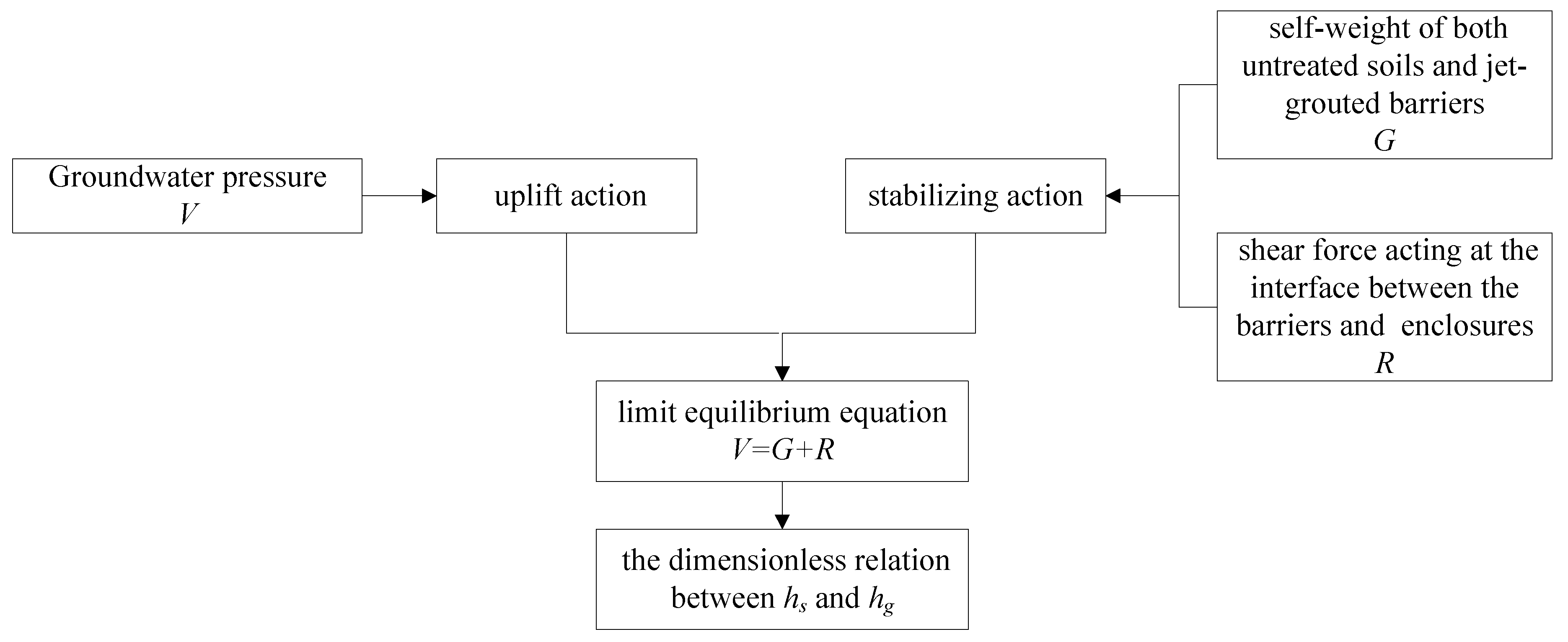
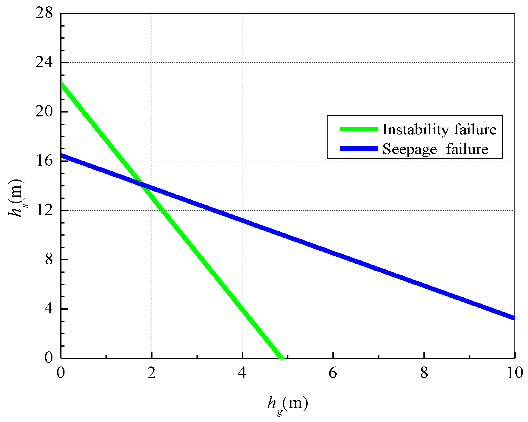
2.3. Calculation of Jet-Grouted Bottom Sealing Barriers Considering Instability Failure

For the instability failure mechanism (shown in Figure 2a), the limit equilibrium equation for the assessment of the instability of jet-grouted bottom sealing barriers can be expressed as:
V = G + R
where V is uplift action of the groundwater pressure acting at the bottom of jet-grouted bottom sealing barriers, G is stabilizing action that is provided by the self-weight of both untreated soils below the excavation bottom and jet-grouted bottom sealing barriers, and R is stabilizing action because of the shear force acting at the interface between the jet-grouted bottom sealing barriers and the underground enclosures. It is noted that stabilizing action of the shear force acting at the interface between untreated soils below the excavation bottom and underground enclosures is herein conservatively neglected.
The water pressure acting on the bottom of jet-grouted bottom sealing barriers can be written as:
V = γ w h u A p
where γw is unit weight of water, hu is head height of water acting at the bottom of jet-grouted bottom sealing barriers, Ap is the area of jet-grouted bottom sealing barriers, for the long rectangle excavation, which can be computed as A p = L · B , and L and B are the length and width of the long rectangle excavation, respectively.
The structures’ self-weight includes the self-weight of both untreated soils below the excavation bottom and jet-grouted bottom sealing barriers, the stabilizing action being provided by the structures’ self-weight G can be computed as:
G = ( γ s h s + γ g h g ) A p
where γs is unit weight of natural soil, γg is unit weight of jet-grouted bottom sealing barriers, hg is the thickness of jet-grouted bottom-sealing barriers, and hs is the depth of untreated soils with regard to the excavation bottom.
The total shear force acting at the interface between the jet-grouted bottom sealing barriers and the underground enclosures R can be expressed as:
R = p h e x c + h s h e x c + h s + h g τ d z = 2 ( B + L ) h e x c + h s h e x c + h s + h g τ d z
where p is perimeter of long rectangle excavation, which can be written as p = 2 · ( L + B ) , hexc is the excavation depth, and τ is the shear stresses acting at the interface between the jet-grouted bottom sealing barriers and the underground enclosures.
Herein, neglecting the frictional effect between jet-grouted bottom sealing barriers and the underground enclosures, the shear strength of the jet-grouted bottom sealing barriers is considered via the Tresca yield criterion. The shear strength τ acting at the interface between the jet-grouted bottom sealing barriers and the underground enclosures can be assumed to coincide with the cohesion cg of the jet-grouted bottom sealing barriers. Besides, the cohesion cg can be expressed as a function of the unconfined compression strength qu of the jet-grouted bottom sealing barriers, namely, the shear strength τ acting at the interface between the jet-grouted bottom sealing barriers and the underground enclosures can be written as:
τ = c g = δ q u
where δ is a constant, which typically ranges between 0.2 and 0.3 [27].
Combined Equations (1)–(5), the limit equilibrium equation for the assessment of the instability of jet-grouted bottom sealing barriers can be expressed as:
γ w h u L B = ( γ s h s + γ g h g ) L B + 2 ( B + L ) δ q u h g
For the long rectangle excavations ( L B ), the jet-grouted bottom sealing barriers can be analyzed as a plane problem, and the limit equilibrium Equation (6) can be approximately computed as
γ w h u B = ( γ s h s + γ g h g ) B + 2 δ q u h g
In common practice, the jet-grouted bottom sealing barriers need to be considered with safety allowance in the design. Taking into account of safety factor Fs, the limit equilibrium Equation (7) for the long rectangle excavations ( L B ) can be written as
F s γ w h u B = ( γ s h s + γ g h g ) B + 2 δ q u h g
Dividing all terms by γ w B 2 and grouping all terms in Equation (8), the dimensionless relation between hs and hg can be expressed as:
h s B = γ w γ s [ F s h u B ( γ g γ w + 2 δ q u γ w B ) h g B ]
Based on the quantitative relationship among geometric dimensions in Figure 2a, the depth of underground enclosures that are embedded in the aquifers hu is expressed as h u = h w + h s + h g . Substituting it into Equation (9), the dimensionless relation between hs and hg further becomes as:
h s B = F s h w B ( γ g γ w + 2 δ q u γ w B F s ) h g B ( γ s γ w F s )
Figure 3 presents the calculation procedure of jet-grouted bottom sealing barriers when considering instability failure.

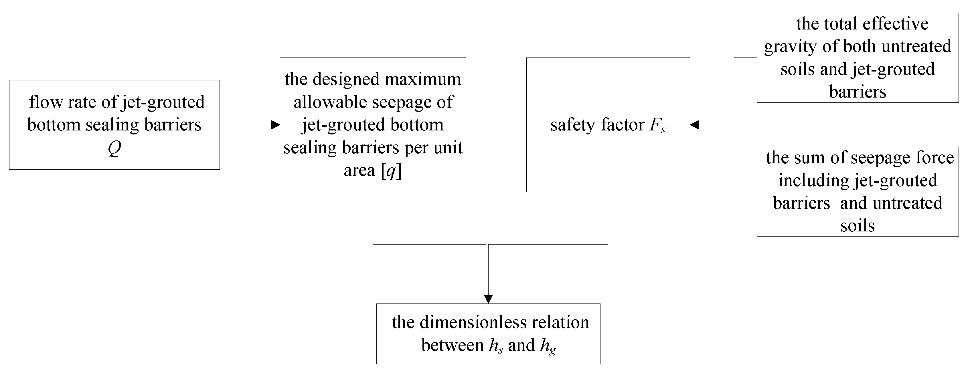
2.4. Calculation of Jet-Grouted Bottom Sealing Barriers Considering Seepage Failure

Ideally, jet-grouted bottom sealing barriers are considered to be almost impermeable materials that have a very low hydraulic conductivity, but in fact jet-grouted materials in the field still have permeability. The hydraulic conductivity of jet grouting in the field is far larger than that obtained by the laboratory test under an ideal condition. When the hydraulic conductivity of the jet-grouted bottom sealing barriers in the field exceeds a certain value, groundwater with high head can induce seepage failure. Therefore, it is necessary to propose a calculation method of the jet-grouted bottom sealing barriers when considering seepage failure. For the seepage failure mechanism, the following assumptions are considered:
(1) The water table is horizontal without considering the fluctuation of groundwater level during pumping inside the excavation.
(2) Groundwater seepage follows Darcy’s law, and it is based on the principle of flow balance; the flow of any cross-section is equal.
(3) The equivalent hydraulic conductivity of multi-layer soils can be expressed as the weighted hydraulic conductivity k = i k i M i M i , where ki and Mi are the hydraulic conductivity and average thickness of each soil layer, respectively.
Followed Darcy’s law, the flow rate Q of any cross-section can be expressed as:
Q = k L B d H d z
Because of the effect of vertical waterproof curtains (underground enclosures), groundwater outside the excavation needs to flow over the underground enclosures and flow towards the excavation through the jet-grouted bottom sealing barriers. By introducing hydraulic boundary conditions of multi-layer soils outside the enclosures: z = h g + h s h u , H = h w ; z = h g + h s , H = h 2 ; the flow rate Q of groundwater outside that flows into the jet-grouted bottom sealing barriers can be calculated based on Equation (11) as
Q = k u L B h w h 2 h u
where ku is the equivalent hydraulic conductivity of multi-layer soils outside the enclosures and h2 is the hydraulic head of groundwater below the jet-grouted bottom sealing barriers.
By introducing hydraulic boundary conditions of jet-grouted bottom sealing barriers: z = h g + h s , H = h 2 ; z = h s , H = h 1 , the flow rate Q of groundwater flows from the jet-grouted bottom sealing barriers (hg) can be computed based on Equation (11), as
Q = k g L B h 2 h 1 h g
where kg is the effective hydraulic conductivity of jet-grouted bottom sealing barriers and h1 is the hydraulic head of groundwater at the top of the jet-grouted bottom sealing barriers.
By introducing hydraulic boundary conditions of untreated soils below the excavation bottom: z = h s , H = h 1 ; z = 0 , H = h 0 , the flow rate Q of untreated soils (hs) below the excavation bottom based on Equation (11) as
Q = k s L B h 1 h 0 h s
where ks is the effective hydraulic conductivity of untreated soils below the excavation bottom and h0 is the hydraulic head of the excavation bottom.
Generally, the water level inside the excavation should be lowered below the excavation bottom, so as to provide dry working space for the excavation. The hydraulic head at the excavation bottom is herein assumed zero after dewatering (h0 = 0), Equation (14) becomes as
Q = k s L B h 1 / h s
By combining Equations (12), (13) and (15), the hydraulic head of groundwater at the bottom (h2) and top (h1) of the jet-grouted bottom sealing barriers as well as the flow rate Q can be, respectively, written as
h 2 = k u k s h g + k u k g h s k s k g h u + k u k s h g + k u k g h s h w
h 1 = k u k g h s k s k g h u + k u k s h g + k u k g h s h w
Q = k u k g k s k s k g h u + k u k s h g + k u k g h s L B h w
Ideally, the expected hydraulic conductivity (kg) of the jet-grouted bottom sealing barriers is quite low, but the hydraulic conductivity (kg) of the jet-grouted bottom sealing barriers in the field is obviously different from the expected value [20,28]. In addition, it is impossible to accurately estimate the hydraulic conductivity of the jet-grouted bottom sealing barriers in advance during the design stage of the jet-grouted bottom sealing barriers, because it is influenced by geological conditions, construction technology, operation methods, and other factors.
For this reason, the maximum acceptable seepage volume per unit area of jet-grouted bottom sealing barriers is taken as the performance control index during the design. When the actual seepage of jet-grouted bottom sealing barriers is less than the designed index, it can be considered that the jet-grouted bottom sealing barriers meets the design requirements. Thus, the following mathematical equation can be obtained based on the criterion of the allowable seepage of jet-grouted bottom sealing barriers:
Q L B = k u k g k s k s k g h u + k u k s h g + k u k g h s h w [ q ]
where [ q ] is the designed maximum allowable seepage of jet-grouted bottom sealing barriers per unit area.
By substituting the quantitative relation among hu, hw, hs and hg (i.e., h u = h w + h s + h g ) into Equation (19), the limit equation for the allowable seepage of jet-grouted bottom sealing barriers can be expressed, as follows:
[ q ] = 1 1 k u + ( 1 k u + 1 k g ) · h g h w + ( 1 k u + 1 k s ) · h s h w
When grouping all terms and dividing all terms by B/hw in Equation (20), the dimensionless equation between the thickness (hg) of jet-grouted bottom sealing barriers and the thickness (hs) of untreated soils below the excavation bottom can be expressed, as follows:
h s B = ( 1 [ q ] 1 k u ) ( 1 k u + 1 k s ) · h w B ( 1 k u + 1 k g ) ( 1 k u + 1 k s ) · h g B
Safety factor Fs can be expressed as the ratio of the total effective gravity to the sum of seepage force (including jet-grouted barriers (hg) and untreated soils (hs)), i.e.,
F s = γ g h g + γ s h s γ w J g h g + γ w J s h s
where γ g is effective unit weight of jet-grouted barriers, γ s is effective unit weight of untreated soils, in the case of multi-layered soils, the value can be computed with a weighted value, and Jg is average hydraulic gradient of jet-grouted bottom sealing barriers, which is expressed as J g = ( h 2 h 1 ) / h g , Js is the average hydraulic gradient of untreated soils, which is expressed as J s = h 1 / h s .
By combining Equations (13), (15) and (22), safety factor Fs can be expressed as
F s = γ g h g + γ s h s γ w Q L B k g h g + γ w Q L B k s h s
For this seepage failure mechanism, the designed index ([q]) of the maximum allowable seepage of jet-grouted bottom sealing barriers per unit area is a given variable. Grouping all the terms in Equation (23), the following equation can be obtained as
1 k g = 1 F s · 1 [ q ] · γ g γ w + 1 F s · 1 [ q ] · γ s γ w · h s h g 1 k s · h s h g
Combining Equations (21) and (24), and eliminating the unknown term kg (hydraulic conductivity of the jet-grouted bottom sealing barriers), the dimensionless equation between thickness hg and the depth hs of jet-grouted bottom sealing barriers can be ultimately expressed, as follows:
h s B = ( 1 [ q ] 1 k u ) ( 1 k u + 1 F s · 1 [ q ] · γ s γ w ) · h w B ( 1 k u + 1 F s · 1 [ q ] · γ g γ w ) ( 1 k u + 1 F s · 1 [ q ] · γ s γ w ) · h g B
Figure 4 presents the calculation procedure of jet-grouted bottom sealing barriers when considering seepage failure.

3. Parametric Analysis and Design Procedure

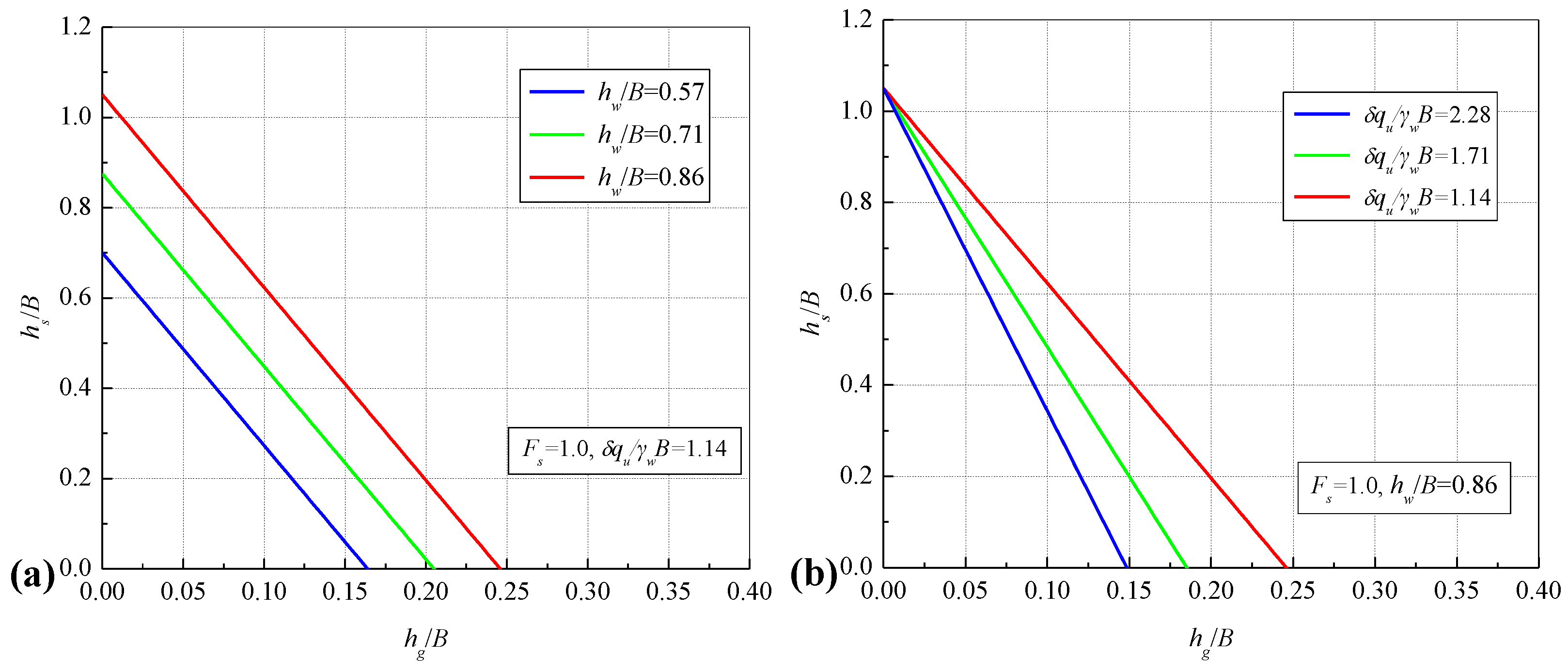
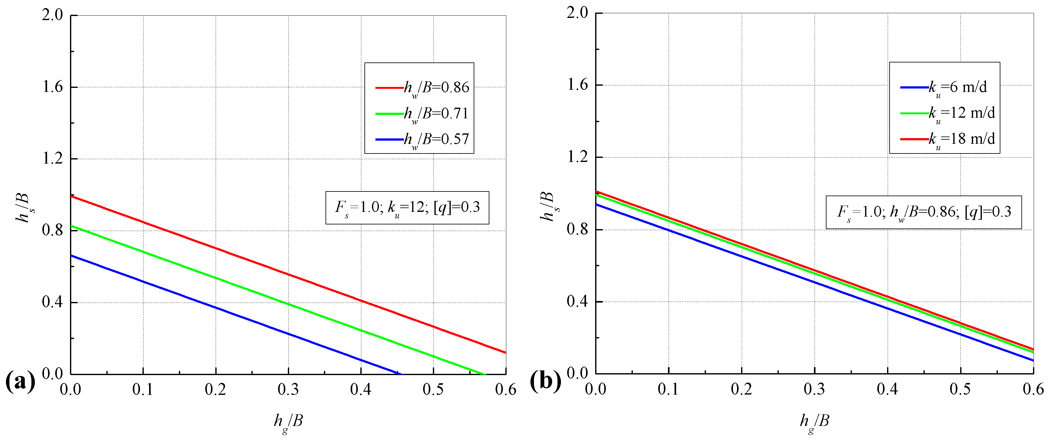
3.1. Parametric Analysis

This part mainly discusses the influence of important parameters on the calculation results for two different failure mechanisms. The deep excavations for urban subway station in China are usually long rectangle excavation ( L B ). The excavation depth of underground two-story station is 15–20 m and the width of the excavation in standard segment is 16–18 m. The regular size of a deep excavation of underground two-story station is considered in the calculation. The excavation width is set as 17.5 m. The homogeneous sandy soil is selected as the representative soil material for discussion. The unit weight of water, jet-grouted material and sandy soil is 10, 22 and 18.16 kN/m3, respectively.
Figure 5a,b display the relation curves of the dimensionless thickness hg/B versus the dimensionless depth hs/B of jet-grouted bottom sealing barriers when considering “instability failure” under the different water table and the unconfined compression strength. As can be seen from Figure 5a,b, when the dimensionless depth hs/B is fixed, for meeting the requirement of the stability, the dimensionless thickness hg/B should increase with the dimensionless water table hw/B, and vice versa. When the dimensionless depth hs/B is fixed, the dimensionless thickness hg/B decreases as the dimensionless term δqu/γwB increases, and vice versa. This suggests that the unconfined compression strength qu of the jet-grouted bottom sealing barriers play a crucial role in the design of the thickness of jet-grouted bottom sealing barriers. The greater the unconfined compression strength qu, the smaller the thickness hg of jet-grouted bottom sealing barriers.
Figure 6a–c display the relation curves of the dimensionless thickness hg/B versus the dimensionless depth hs/B of jet-grouted bottom sealing barriers when considering “seepage failure” under the different water table, the equivalent hydraulic conductivity of soils and the allowable seepage of jet-grouted bottom sealing barriers per unit area, respectively. As can be seen from Figure 6a–c, when the dimensionless thickness hg/B is fixed, to prevent from seepage failure the dimensionless depth hs/B should increase with the dimensionless water table hw/B, and vice versa. When the dimensionless thickness hg/B is fixed, the dimensionless depth hs/B should increase as the equivalent hydraulic conductivity of soils ku becomes large, and vice versa. When the dimensionless depth hs/B and the equivalent hydraulic conductivity of soils ku are fixed, the dimensionless thickness hg/B decreases as the allowable seepage of jet-grouted bottom sealing barriers per unit area [q] increases, but the allowable seepage of the jet-grouted bottom sealing barriers per unit area [q] varies between 0.01 and 0.3, the effect of which plays on the dimensionless thickness hg/B or the dimensionless depth hs/B is not significant.

3.2. Design Procedure

Generally, the design parameters of the jet-grouted bottom sealing barriers often involve the two important parameters of thickness hg and depth hs (or called the thickness of untreated soils). If the terms hs is quite large, field construction of jet-grouted bottom sealing barriers may not be achieved; otherwise, if jet-grouted bottom sealing barriers is relatively thick, the construction cost will be expensive. Therefore, comprehensive comparison between the two important parameters hg and hs is needed in the design, so as that a set of optimized design parameters are determined for the design of jet-grouted bottom sealing barriers.
The calculation methods of jet-grouted bottom sealing barriers considering instability failure and seepage failure mechanism are proposed in Section 2.3 and Section 2.4, respectively. Based on these different calculation methods, the optimum design procedure for the determination of the parameters of jet-grouted bottom sealing barriers can be further formed, including:
(1) According to the actual geology and hydrology condition of a deep excavation as well as excavation size, the values of variables that have been known (e.g., B, hw, [q], hw, etc.) are determined in advance. When substituting these values into Equations (10) and (25), the quantitative relation between the dimensionless thickness of jet-grouted bottom sealing barriers (hg/B) and the dimensionless thickness of untreated soils (hs/B) can be given when considering instability failure and seepage failure mechanism, respectively.
(2) When considering specific safety factor Fs, the relation curves of hg/B versus hs/B are plotted in view of instability failure and seepage failure mechanism, respectively. Based on the plotting charts, the design parameters of jet-grouted bottom sealing barriers can be reasonably determined.

4. Application

4.1. Case Study

The proposed design procedure has been applied to a case study of a deep excavation of metro station in Fuzhou City, China. The excavation is carried out by “bottom-up” construction method. The length and width of the excavation is 200 m and 19.7 m, respectively. The underground enclosures are composed of 80 cm thick diaphragm walls. The geology at site is mainly composed of miscellaneous fill, silt, silt with sand, fine-medium sand with silt, silty clay, medium-coarse sand, silt with sand and gravel. The typical geology profile is presented in Figure 7. Table 1 lists the physico-mechanical properties of soils from the laboratory test.
The hydrogeology at the site is a multi–aquifer–aquitard system (MAAS). The groundwater system is mainly composed of a phreatic aquifer and two confined aquifers (I and II). The confined aquifer I consists of fine-medium sand with silt, which has a piezometric head of 4.0–5.0 m below he ground surface (BGS). The confined aquifer II consists of medium-coarse sand and gravel, and the piezometric head of confined aquifer II is 3.0–4.0 m BGS. The aquitards (e.g., silt with sand, silty clay) are discontinuous at the excavation site. Due to the partial presence of skylights of the upper confining bed in confined aquifers at the central area of the excavation site, there is a very close hydraulic relation between confined aquifer I and II, resulting in a great challenge for groundwater control during excavation. Massive jet-grouted bottom sealing barriers are applied for the excavation to lower the water lever inside the excavation and simultaneously minimize the effect of pumping on adjoining buildings and utilities outside the excavation.

4.2. Design of Jet-Grouted Bottom Sealing Barriers

Table 2 lists the calculating parameters that have been known for the design of jet-grouted bottom sealing barriers. Considering such factors for importance of the excavation, uncertainty of jet grouting and safety allowance, safety factor Fs is set as 1.2 for the design of jet-grouted bottom sealing barriers. Figure 8 presents the relation curves of hg versus hs under the condition of both instability failure and seepage failure. The intersection of the two curves of hg versus hs plotted in Figure 8 should be a set of optimum solutions for the design of jet-grouted bottom sealing barriers, namely, hs is 14 m and hg is 1.8 m. On the one hand, it can prevent “instability failure” and “seepage failure” of jet-grouted bottom sealing barriers, so as to avoid the occurrence of, and on the other hand, the thickness of jet-grouted bottom sealing barriers is not very large, so that the excavation cost is not expensive.
However, when considering the safety allowance and uncertainty factors during construction, the thickness of jet-grouted bottom sealing barriers is conservatively designed as 5 m (larger than the calculated thickness 1.8 m). Finally, the depth of untreated soils and thickness of jet-grouted bottom sealing barriers are determined to be 14 m and 5 m, respectively, as shown in Figure 9. The designed diameter and center spacing of the jet grouting columns is 1.1 m and 0.75 m, respectively.
The double high-pressure jet grouting technique that develops on the traditional triple-rod method is used for the construction due to the deep depth of jet-grouted bottom sealing barriers that are below the ground surface. Table 3 lists the construction parameters of the jet grouting columns.

4.3. Pumping Test Results And Analyses

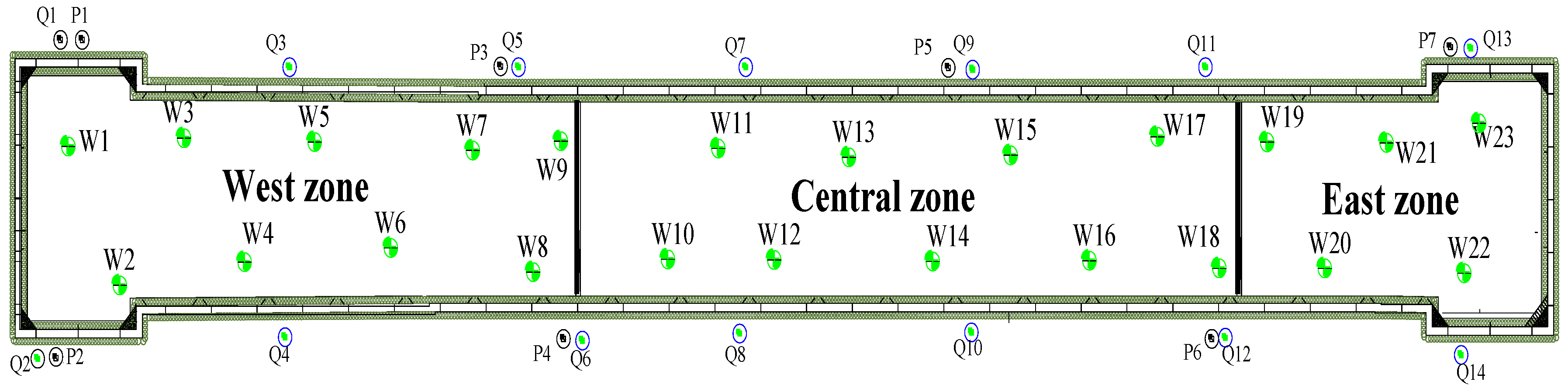
4.3.1. Pumping Test Scheme

Field pumping tests were performed prior to the excavation to assess the effectiveness of massive jet-grouted bottom sealing barriers to groundwater control for the excavation. Figure 10 displays the location of all the pumping wells and observation wells installed inside and outside the excavation, respectively. 23 pumping wells (labelled W1 to W23) were screened at the depth of 24–25 m BGS in three excavation zones (West zone, Central zone, and East zone). A total of 21 observation wells (labelled Q1 to Q14 and S1 to S7) were screened at different depths to measure the drawdown outside. Table 4 illustrates the detailed procedure of the field pumping tests.

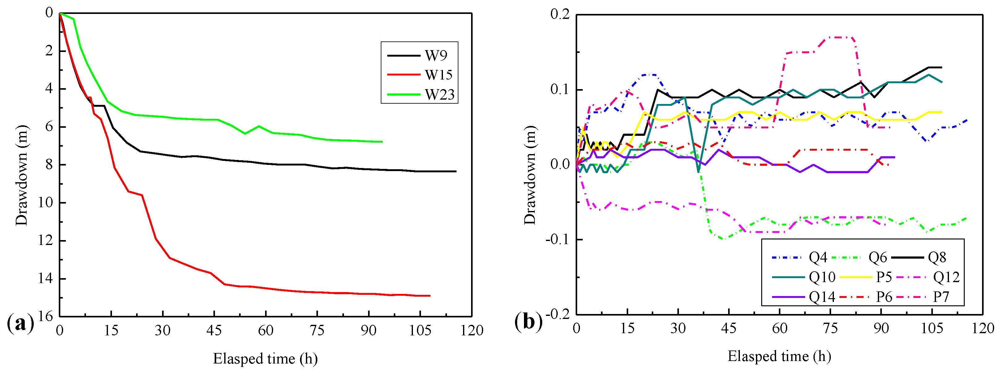
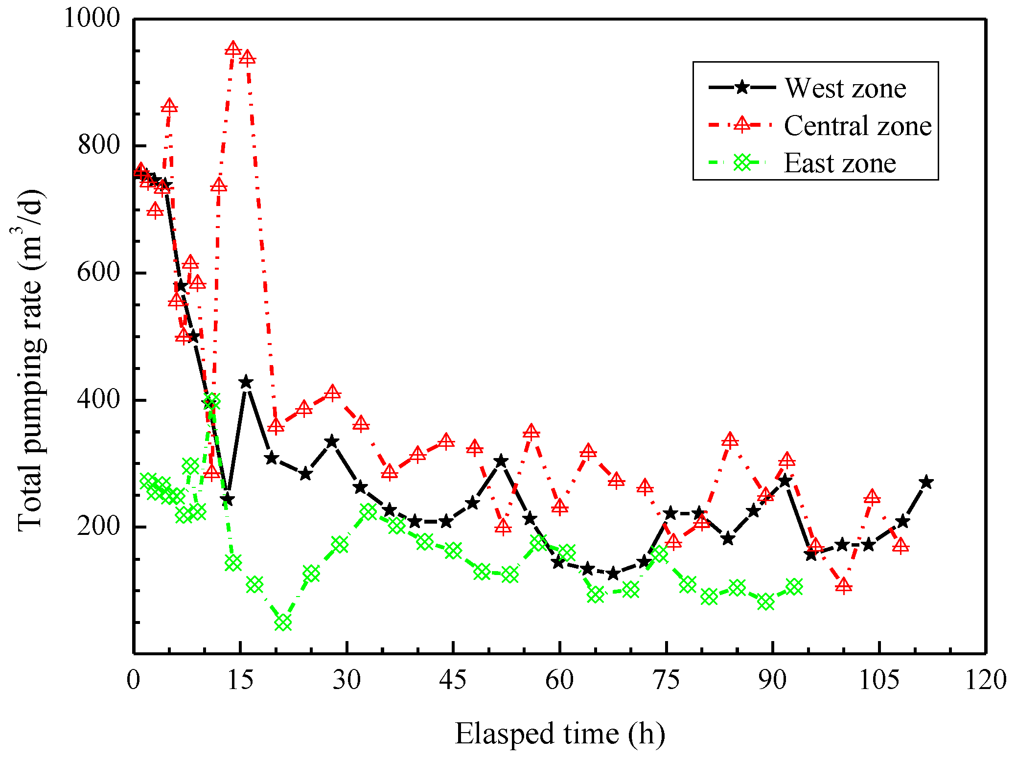
4.3.2. Pumping Test Results and Analyses

(1) Groundwater drawdown
Figure 11a,b display the variation of groundwater drawdown in observation wells that were installed inside and outside the excavation during pumping test. As can be seen from Figure 11a, the stabilized drawdown of well W9 inside the West zone was about 8.4 m after the 24 h pumping test. The maximum drawdown of observation wells installed inside the Central zone is up to 14.9 m, being located at well W15 after the 48 h pumping test. The stabilized drawdown of well W23 inside the East zone was about 6.8 m after he 80 h pumping test. Due to the lower water level at both the West and East zone from the results of the initial observation, the water table inside the excavation could be lowered to the excavation bottom. As shown in Figure 11b, the maximum groundwater drawdown outside the West zone, Central zone, and East zone was 0.16 m, 0.18 m, and 0.1 m when the water level inside stabilized.
(2) Pumping rate of wells
Figure 12 displays the evolution of the pumping rate of operative wells installed inside the excavation during the pumping test. It can be seen that the total pumping rate of operative wells gradually decreased as the pumping test went. After the stabilization of water level, the total pumping rate of all operative wells in the West zone, Central zone, and East zone was 270.24, 169.92, and 109.68 m3/d, respectively. When compared with the data measured at the initial period of pumping test, the total pumping rate of wells obviously decreased, especially the total pumping rate of wells in the central zone declined by more than 75%.

4.4. Discussion

In fact, when the water table inside stabilizes, the total pumping rate of all operative pumping wells will be approximately equivalent to the leakage of jet-grouted bottom sealing barriers in case of neglecting the leakage of the underground enclosures. From the results of the field pumping test, the daily water inflow towards the excavation is about 550 m3 when the water table inside stabilizes. To some extent, this proves the truth that, although jet-grouted bottom sealing barriers can greatly reduce the water inflow, it still has permeability and it is not able to completely cut off the groundwater below. Therefore, it is necessary and practical to propose a design method of jet-grouted bottom sealing barriers when considering seepage failure.
Furthermore, the variation of groundwater drawdown measured outside the excavation is less than 0.2 m. This suggests that the jet-grouted bottom sealing barriers play a crucial role for cutting off groundwater, resulting in dewatering inside having little impact outside the excavation. This paper proposes the calculation method of jet-grouted bottom sealing barriers considering seepage failure mechanism, which is based on the hypotheses without considering the fluctuation of groundwater level during pumping inside the excavation. The results of groundwater drawdown measured outside the excavation during pumping inside also prove the validity of this hypothesis to some extent.
The area of jet-grouted bottom sealing barriers that were applied for the excavation case is about 3600 m2, that is, the seepage flow rate per unit area of jet-grouted bottom sealing barriers (1 m2) is 0.15 m3/d, which is less than the maximum allowable seepage flow rate per unit area of jet-grouted bottom sealing barriers (0.25 m3/d). This implies that the performance of jet-grouted bottom sealing barriers applied for the excavation case is good, which meets the requirements of design and safety.

5. Concluding Remarks

The calculation method of jet-grouted bottom sealing barriers applied for deep excavations in deep aquifers are proposed when considering the two different failure mechanisms (“instability failure” and “seepage failure”). The design procedure for the determination of the parameters of jet-grouted bottom sealing barriers is also proposed when considering both of the failure mechanisms. The proposed design procedure is applied to an excavation of a metro station in Fuzhou City, China.
The field pumping tests prove that the performance of jet-grouted bottom sealing barriers is good. On the one hand, it ensures that the water level inside the excavation can reach the desired level (the maximum drawdown inside up to 14.9 m); on the other hand, it minimized the groundwater drawdown outside (the maximum drawdown outside less than 0.2 m). In the later stage of the stabilization of pumping inside, the leakage of the deep horizontal bottom sealing curtain per unit area of foundation pit is lower than the maximum allowable seepage designed.
The design procedure that is proposed in this paper provides a scientific theory for the determination of the parameters of jet-grouted bottom sealing barriers. In this way, the design of jet-grouted bottom sealing barriers can be more scientific and reasonable. Unfortunately, this design procedure herein proposed in this paper can only design the depth and thickness of jet-grouted bottom sealing barriers that are used for a deep excavation. In fact, both the spacing and diameter of jet grouting columns are quite critical in the design of jet-grouted bottom sealing barriers. The problem will be discussed in depth in future work.

Author Contributions

Methodology, C.C.; Writing—original draft preparation, C.C.; Writing—review and editing, C.S. and M.L.; Supervision, C.S.; project administration, C.S.; funding acquisition, C.S.

Funding

This research was funded by [National Natural Science Foundation of China] grant number [51778636] And The APC was funded by [National Natural Science Foundation of China (51778636)].

Acknowledgments

The authors are grateful for the funds provided by Guangzhou Metro Design & Research Institute Co., Ltd. and CCCC Strait Construction Investment and Development Co., Ltd. The authors also thank CCCC First Harbor Engineering Co., Ltd. for cooperation in the field tests and data collection for this study.

Conflicts of Interest

The authors declare no conflict of interest.

Nomenclature

Llength of rectangular excavationBwidth of rectangular excavation
pperimeter of long rectangle excavationAparea of jet-grouted bottom sealing barriers
hexcdepth of rectangular excavationhwgroundwater head with regard to excavation bottom
hgthickness of jet-grouted bottom-sealing barriershsdepth of untreated soils with regard to excavation bottom
hudepth of enclosures embedded in the aquifersγwunit weight of water
γsunit weight of natural soilγgunit weight of jet-grouted bottom sealing barriers
γ s effective unit weight of untreated soils γ g effective unit weight of jet-grouted barriers
quunconfined compression strength of jet-grouted materialscgcohesion of jet-grouted materials
kihydraulic conductivity of each soil layerMithe average thickness of each soil layer
kuequivalent hydraulic conductivity of multi-layer soilskseffective hydraulic conductivity of untreated soils
kgeffective hydraulic conductivity of bottom sealing barriers τ shear strength of jet-grouted materials
h1hydraulic head at the top of the jet-grouted barriersh2hydraulic head at the bottom of the jet-grouted barriers
h0hydraulic head of the excavation bottomQflow rate of bottom sealing barriers
Jgaverage hydraulic gradient of jet-grouted barriersJsaverage hydraulic gradient of and untreated soils
Vuplift action of the groundwater pressureRstabilizing action of the shear force
Gstabilizing action provided by self-weight of both untreated soils and jet-grouted barriers
[q]designed allowable seepage of bottom sealing barriers per unit area

References

  1. Chen, J.J.; Zhang, L.Y.; Zhang, J.F.; Zhu, Y.F.; Wang, J.H. Field tests, modification, and application of deep soil mixing method in soft clay. J. Geotech. Geoenviron. Eng. 2013, 139, 24–34. [Google Scholar] [CrossRef]
  2. Xu, Y.S.; Shen, S.L.; Ma, L.; Sun, W.J.; Yin, Z.Y. Evaluation of the blocking effect of retaining walls on groundwater seepage in aquifers with different insertion depths. Eng. Geol. 2014, 183, 254–264. [Google Scholar] [CrossRef]
  3. Wang, Z.F.; Shen, S.L.; Ho, C.E.; Kim, Y.H. Investigation of field-installation effects of horizontal twin-jet grouting in Shanghai soft soil deposits. Can. Geotech. J. 2013, 50, 288–297. [Google Scholar] [CrossRef]
  4. Kimura, M.; Inazumi, S.; Too, J.K.A.; Isobe, K.; Mitsuda, Y.; Nishiyama, Y. Development and application of H-joint steel pipe sheet piles in construction of foundation for structures. Soils Found. 2007, 47, 237–251. [Google Scholar] [CrossRef]
  5. Ding, Y.; Wang, P.; Yu, S. A new method for deformation monitoring on H-pile in SMW based on BOTDA. Measurement 2015, 70, 156–168. [Google Scholar] [CrossRef]
  6. Zhou, N.; Vermeer, P.; Lou, R.; Tang, Y.; Jiang, S. Numerical simulation of deep foundation pit dewatering and optimization of controlling land subsidence. Eng. Geol. 2010, 114, 251–260. [Google Scholar] [CrossRef]
  7. Shi, C.; Cao, C.; Lei, M.; Peng, L.; Jiang, J. Optimal design and dynamic control of construction dewatering with the consideration of dewatering process. Ksce J. Civ. Eng. 2017, 21, 1161–1169. [Google Scholar] [CrossRef]
  8. Roy, D.; Robinson, K.E. Surface settlements at a soft soil site due to bedrock dewatering. Eng. Geol. 2009, 107, 109–117. [Google Scholar] [CrossRef]
  9. Forth, R.A. Groundwater and geotechnical aspects of deep excavations in Hong Kong. Eng. Geol. 2004, 72, 253–260. [Google Scholar] [CrossRef]
  10. Shen, S.L.; Wu, Y.X.; Misra, A. Calculation of head difference at two sides of a cut-off barrier during excavation dewatering. Comput. Geotech. 2017, 91, 192–202. [Google Scholar] [CrossRef]
  11. Wang, J.X.; Liu, X.T.; Wu, Y.B.; Liu, S.L.; Wu, L.G.; Lou, R.X.; Lu, J.S.; Yao, Y. Field experiment and numerical simulation of coupling non-Darcy flow caused by curtain and pumping well in foundation pit dewatering. J. Hydrol. 2017, 549, 277–293. [Google Scholar] [CrossRef]
  12. Wang, J.X.; Liu, X.T.; Liu, S.L.; Zhu, Y.F.; Pan, W.Q.; Zhou, J. Physical model test of transparent soil on coupling effect of cut-off wall and pumping wells during foundation pit dewatering. Acta Geotech. 2018, 14, 141–162. [Google Scholar] [CrossRef]
  13. Wu, Y.X.; Shen, S.L.; Xu, Y.S.; Yin, Z.Y. Characteristics of groundwater seepage with cutoff wall in gravel aquifer. I: field observations. Can. Geotech. J. 2015, 52, 1526–1538. [Google Scholar]
  14. Wu, Y.X.; Shen, S.L.; Yuan, D.J. Characteristics of dewatering induced drawdown curve under blocking effect of retaining wall in aquifer. J. Hydrol. 2016, 539, 554–566. [Google Scholar] [CrossRef]
  15. Wu, Y.X.; Shen, S.L.; Cheng, W.C.; Hino, T. Semi-analytical solution to pumping test data with barrier, wellbore storage, and partial penetration effects. Eng. Geol. 2017, 226, 44–51. [Google Scholar] [CrossRef]
  16. Zeng, C.F.; Xue, X.L.; Zheng, G.; Xue, T.Y.; Mei, G.X. Responses of retaining wall and surrounding ground to pre-excavation dewatering in an alternated multi-aquifer-aquitard system. J. Hydrol. 2018, 559, 609–626. [Google Scholar] [CrossRef]
  17. Croce, P.; Modoni, G. Design of jet-grouting cut-off. Ground Improv. 2007, 11, 11–19. [Google Scholar] [CrossRef]
  18. Pujades, E.; Carrera, J.; Vàzquez-Suñé, E.; Jurado, A.; Vilarrasa, V.; Mascuñano-Salvador, E. Hydraulic characterization of diaphragm walls for cut and cover tunnelling. Eng. Geol. 2012, 125, 1–10. [Google Scholar] [CrossRef]
  19. Pujades, E.; Jurado, A.; Carrera, J.; Vàzquez-Suñé, E.; Dassargues, A. Hydrogeological assessment of non-linear underground enclosures. Eng. Geol. 2016, 207, 91–102. [Google Scholar] [CrossRef]
  20. Vilarrasa, V.; Carrera, J.; Jurado, A.; Pujades, E.; Vazquez-Sune, E. A methodology for characterizing the hydraulic effectiveness of an annular low-permeability barrier. Eng. Geol. 2011, 120, 68–80. [Google Scholar] [CrossRef]
  21. Ochmański, M.; Modoni, G.; Bzòwka, J. Prediction of the diameter of jet grouting columns with artificial neural networks. Soils Found. 2015, 55, 425–436. [Google Scholar] [CrossRef] [Green Version]
  22. Van Tol, A.F. Lessons Learned from Jetgrouting at A Tunnel Project in the Haghe; Dhouib, A., Magnan, J.P., Mastat, P., Eds.; LCPC: Paris, France, 2004; pp. 321–331. [Google Scholar]
  23. Flora, A.; Lirer, S.; Lignola, G.P.; Modoni, G. Mechanical Analysis of jet-grouted supporting structures. In Proceedings of the 7th International Symposium on Geotechnical Aspects of Underground Construction in Soft Ground, Taylor & Francis Group, Boca Raton, FL, USA, 15 May 2011. [Google Scholar]
  24. Modoni, G.; Croce, P.; Mongiovi, L. Theoretical modelling of jet grouting. Geotechnique 2006, 56, 335–347. [Google Scholar] [CrossRef]
  25. Shen, S.L.; Wang, Z.F.; Horpibulsuk, S.; Kim, Y.H. Jet grouting with a newly developed technology: The Twin-Jet method. Eng. Geol. 2013, 152, 87–95. [Google Scholar] [CrossRef]
  26. Shen, S.L.; Wang, Z.F.; Sun, W.J.; Wang, L.B.; Horpibulsuk, S. A field trial of horizontal jet grouting using the composite-pipe method in the soft deposit of Shanghai. Tunn. Undergr. Space Technol. 2013, 35, 142–151. [Google Scholar] [CrossRef]
  27. Croce, P.; Flora, A.; Modoni, G. Jet Grouting Technology, Design and Control; CRC: New York, NY, USA, 2014. [Google Scholar]
  28. Pujades, E.; Vàzquez-Suñé, E.; Carrera, J.; Vilarrasa, V.; De Simone, S.; Jurado, A.; Ledesma, A.; Ramos, G.; Lloret, A. Deep enclosures versus pumping to reduce settlements during shaft excavations. Eng. Geol. 2014, 169, 100–111. [Google Scholar] [CrossRef]
Figure 1. Plan view of jet-grouted bottom sealing barriers.
Applsci 09 02307 g001
Figure 2. Failure mechanisms of jet-grouted bottom sealing barriers: (a) Instability failure; (b) Seepage failure.
Applsci 09 02307 g002
Figure 3. Calculation procedure of jet-grouted bottom sealing barriers considering instability failure.
Applsci 09 02307 g003
Figure 4. Calculation procedure of jet-grouted bottom sealing barriers considering seepage failure.
Applsci 09 02307 g004
Figure 5. Relation curves of hg/B versus hg/B when considering “instability failure”: (a) water table; and, (b) unconfined compression strength.
Applsci 09 02307 g005
Figure 6. Relation curves of hg/B versus hg/B considering “seepage failure”: (a) water table; (b) equivalent hydraulic conductivity of soils; and, (c) allowable seepage of jet-grouted bottom sealing barriers per unit area.
Applsci 09 02307 g006aApplsci 09 02307 g006b
Figure 7. Typical geology profile at site.
Applsci 09 02307 g007
Figure 8. Relation curve of depth hs versus thickness hg of jet-grouted bottom sealing barriers.
Applsci 09 02307 g008
Figure 9. Design of jet-grouted bottom sealing barriers.
Applsci 09 02307 g009
Figure 10. The location of the pumping and observation wells.
Applsci 09 02307 g010
Figure 11. Variation of the drawdown measured in observation wells: (a) inside the excavation; and, (b) outside the excavation.
Applsci 09 02307 g011
Figure 12. Time-history curves of pumping rate of wells in different excavation zone.
Applsci 09 02307 g012
Table 1. Physico-mechanical properties of soil at the site.
Soil LayerAverage Thickness
(m)
Hydraulic ConductivityVoid Ratio
e
Unit Weight
γ (kN/m3)
Compression Modulus
Es (MPa)
kh (m/d)kv (m/d)
miscellaneous fill2.88.64 × 10−2-18.54.0
silt4.20.000850.000461.7115.61.6
silt with sand4.30.131.6015.94.0
fine-medium sand with silt10.08.5-18.56.0
silty clay3.00.0040.0030.7119.27.0
medium-coarse sand11.015-19.013.0
silt with sand20.131.117.43.5
gravel8.040-18.040.0
Table 2. Calculating parameter.
VariablesB (m)γs (kN/m3)γw (kN/m3)γg (kN/m3)ku (m/d)hw (m)hexc (m)[q] (m/d)cg (kPa)
Value18.119102211.513160.25200
Note that unit weight of natural soil γs and the hydraulic conductivity of multi-layer soils ku are taken a weighted value.
Table 3. Construction parameters of jet grouting columns.
PropertiesGroutWaterAirRod Lifting Rate
(cm/min)
Rod Rotation Rate
(rpm)
Pressure
(MPa)
Flow Rate
(L/min)
Water-Cement Ratio by WeightPressure
(MPa)
Flow Rate
(L/min)
Pressure
(MPa)
Flow Rate
(m3/min)
Range value 351001:125–35700.861210
Table 4. Procedure of pumping tests.
TestSubsectionPumping WellsObservation WellsPumping Time (d)
InsideOutside
West ZoneW1, W3, W4, W5, W6, W7, W8W9Q2, Q4, Q6, P2, P45
Central ZoneW10, W12, W13, W14, W16, W17W15Q6, Q8, Q10, Q12, P4, P5, P64.5
East ZoneW18, W19, W20, W21, W22W23Q12, Q14, P6, P74

