
The Development of a 3D-Printed Compliant System for the Orientation of Payloads on Small Satellites: Material Characterization and Finite Element Analysis of 3D-Printed Polyetherketoneketone (PEKK)
Abstract
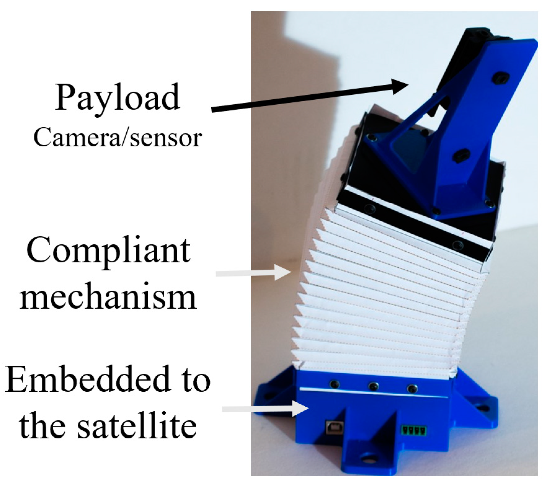
:1. Introduction
2. Materials and Methods
2.1. Material
2.2. Process
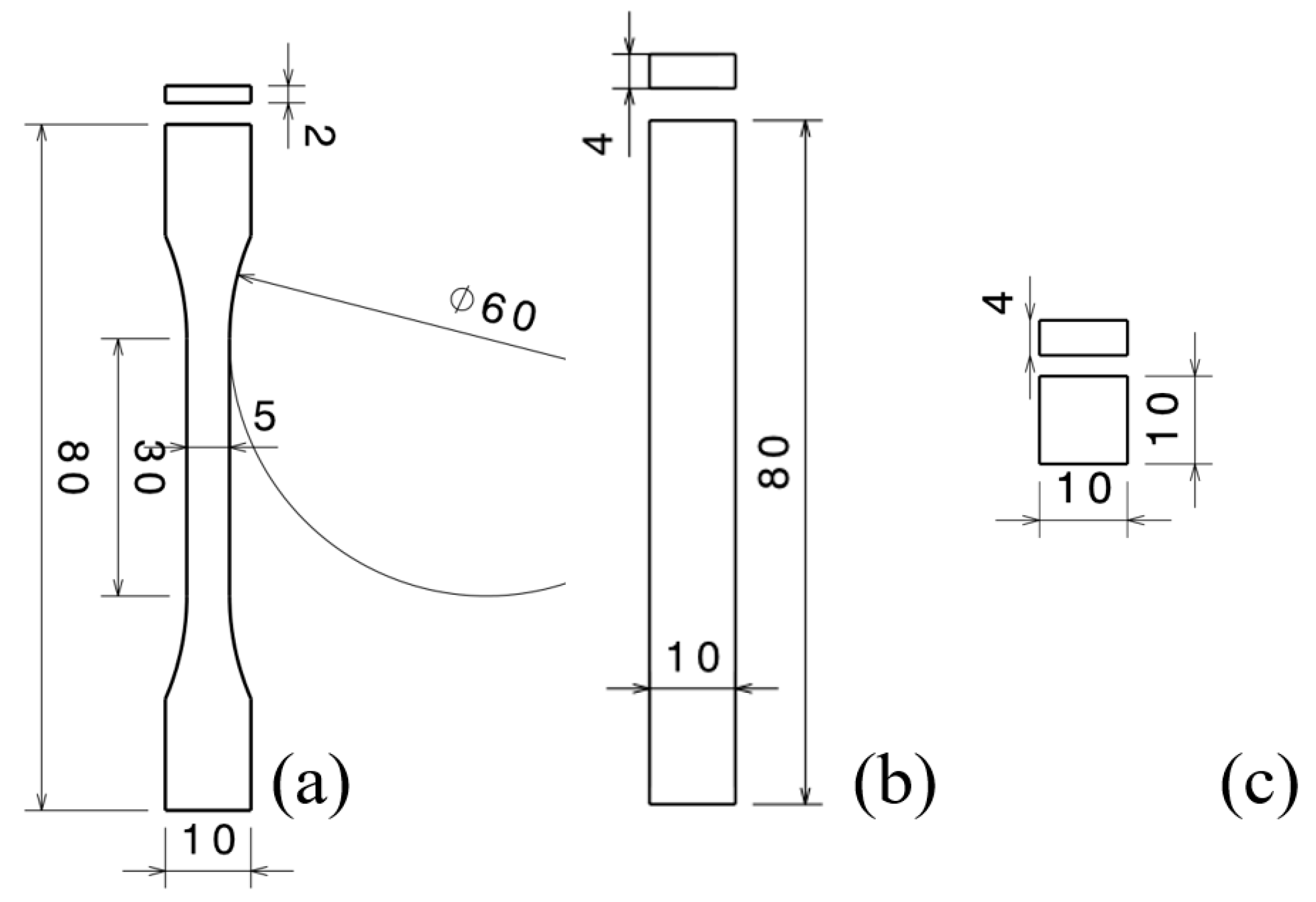
2.2.1. Mechanical Characterization
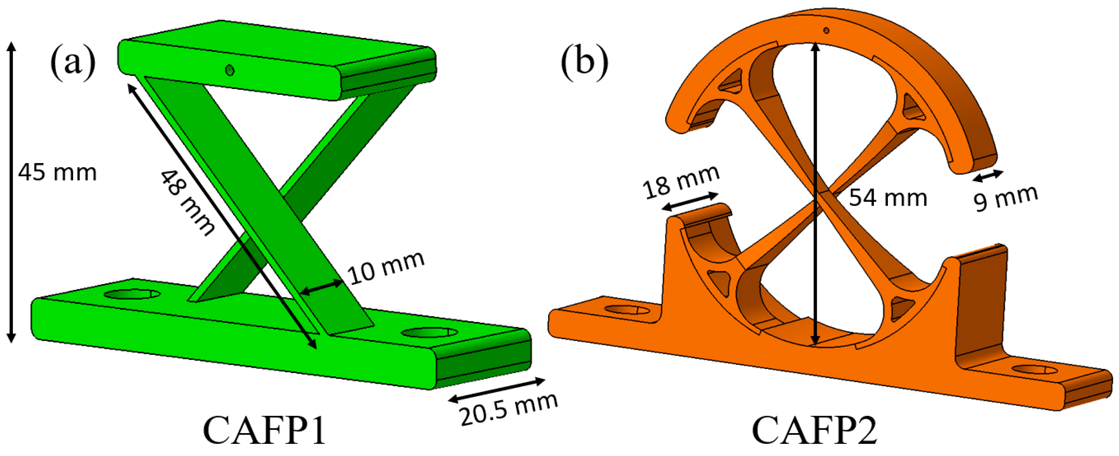
2.2.2. Cross-Axis Flexural Pivots
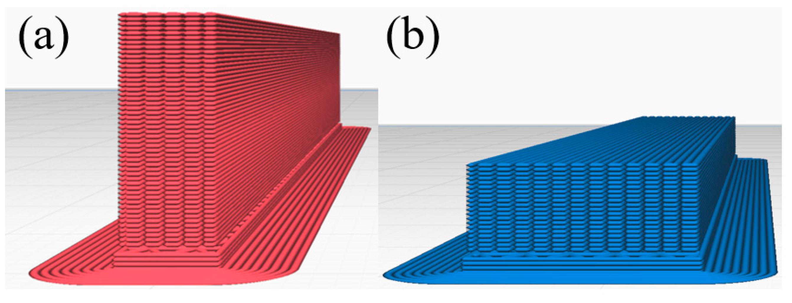
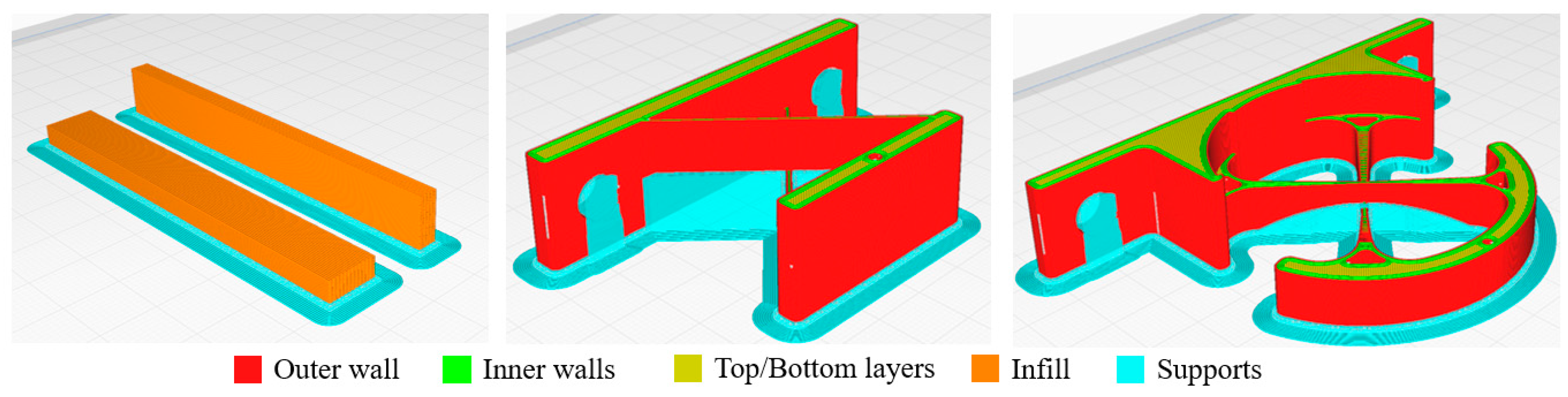
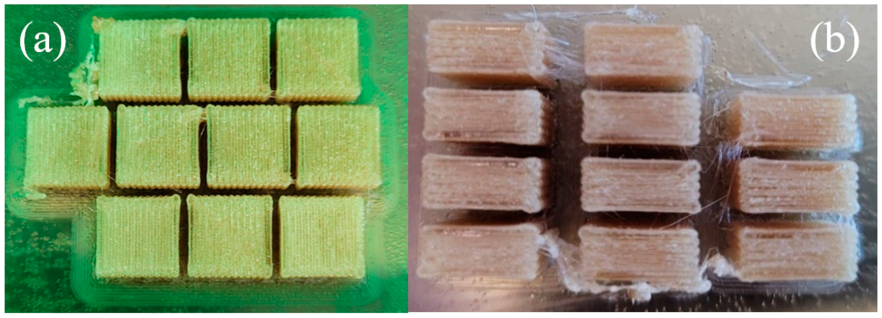
2.2.3. From CAD to Printing
2.3. Methods and Test Equipment
3. Results and Discussion
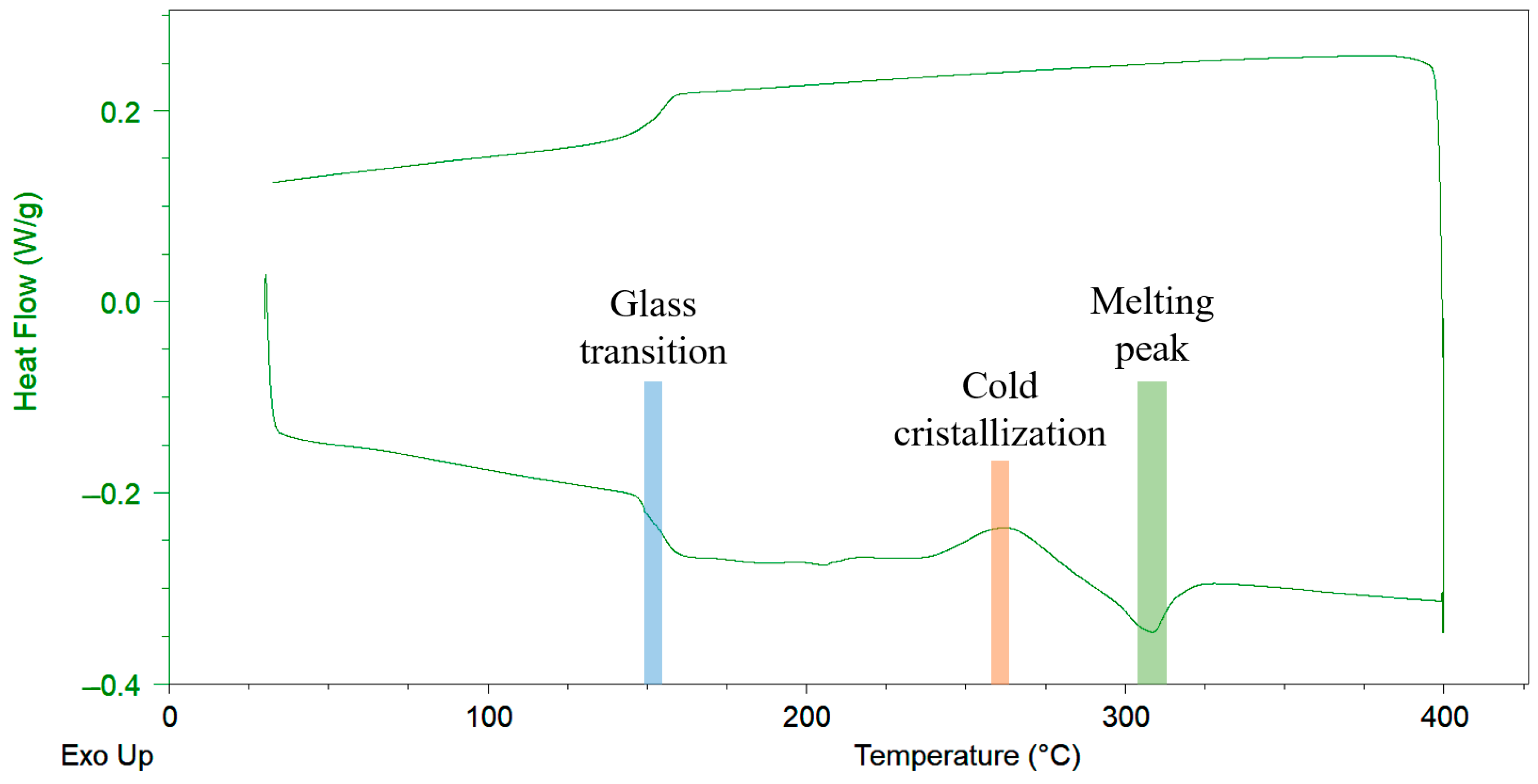
3.1. Thermal Properties
3.2. Mechanical Properties
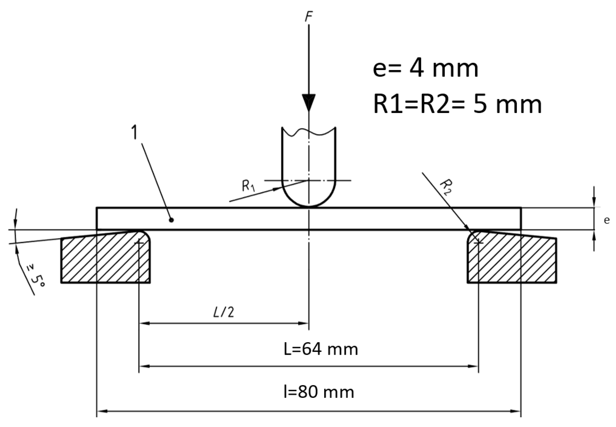
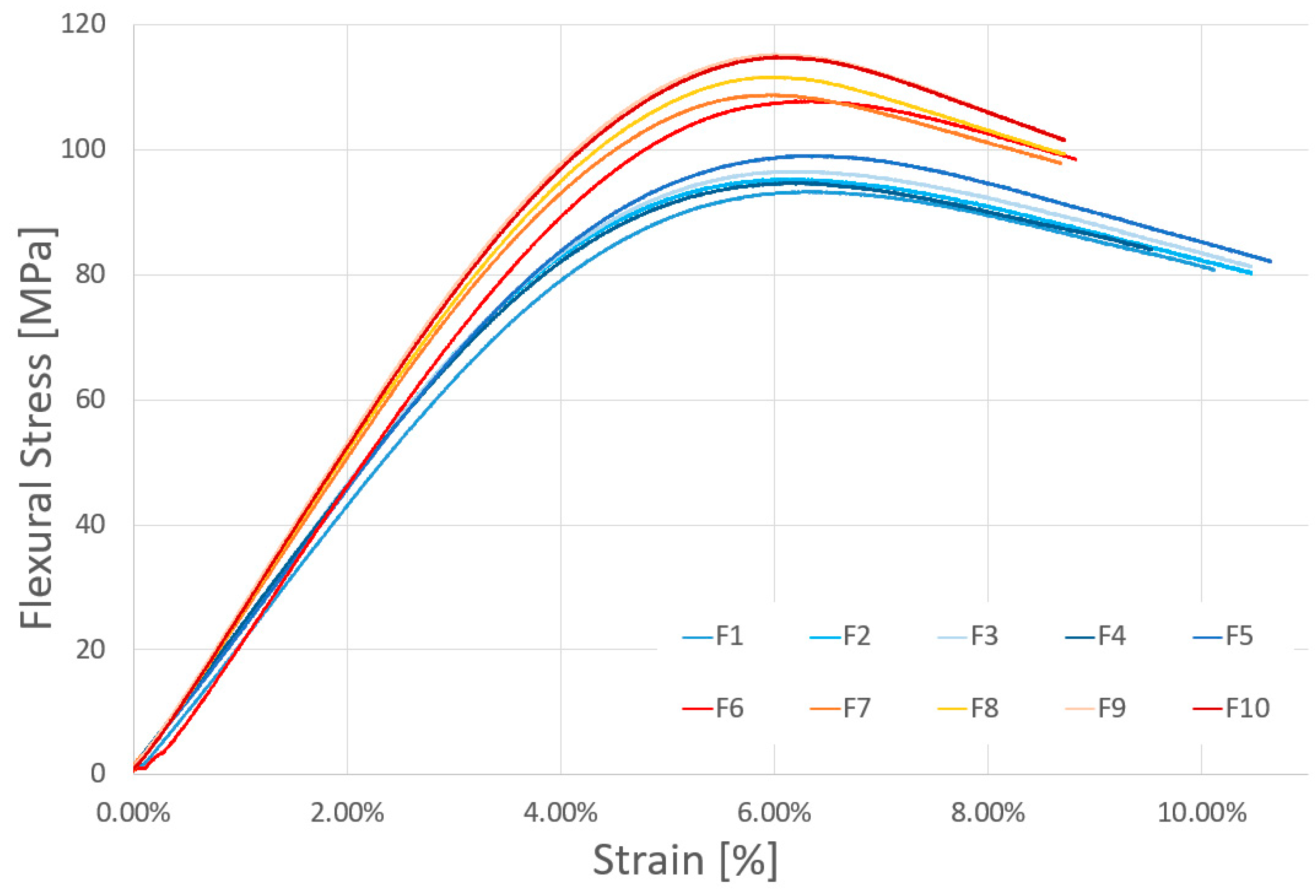
3.2.1. Flexural Tests
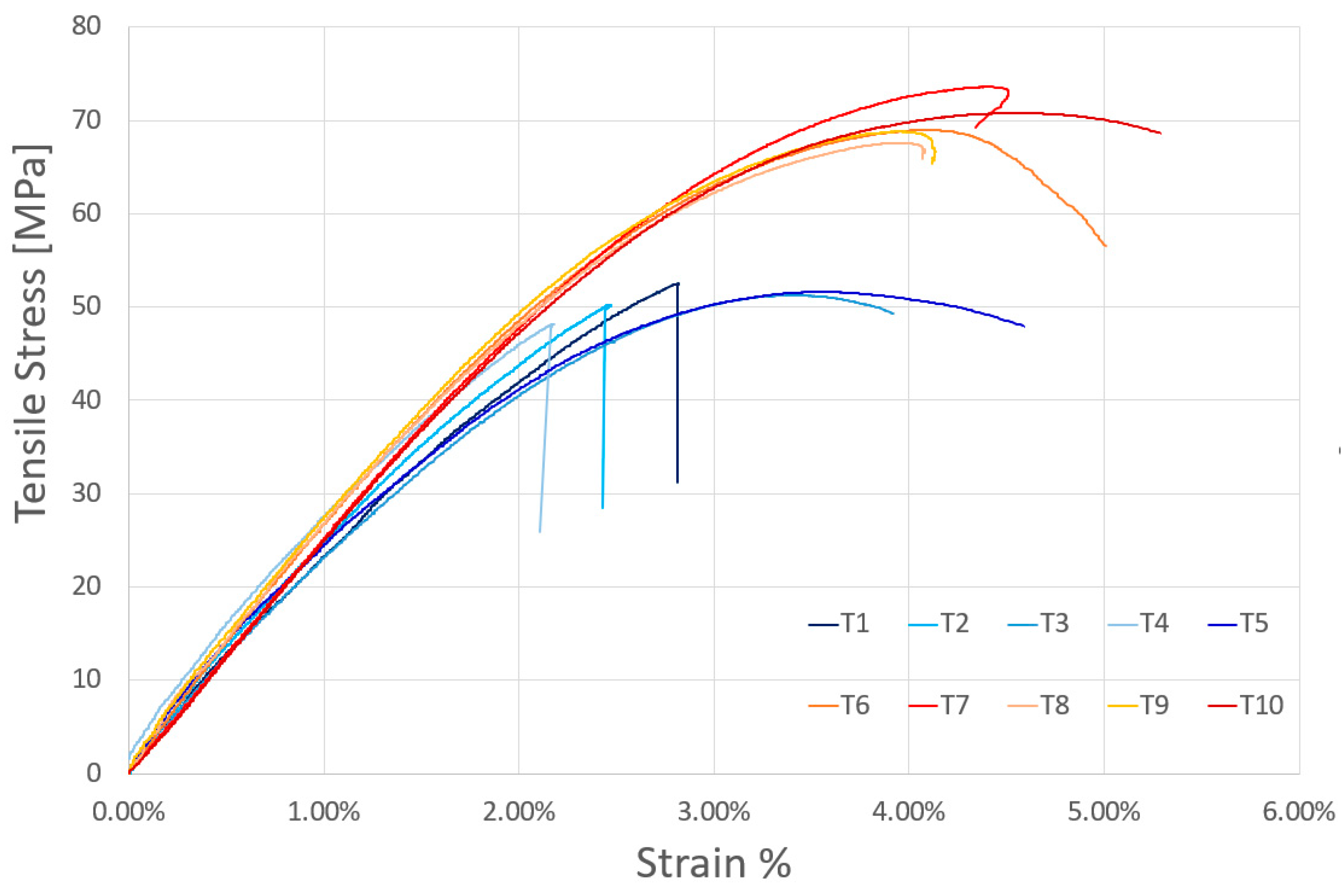
3.2.2. Tensile Tests
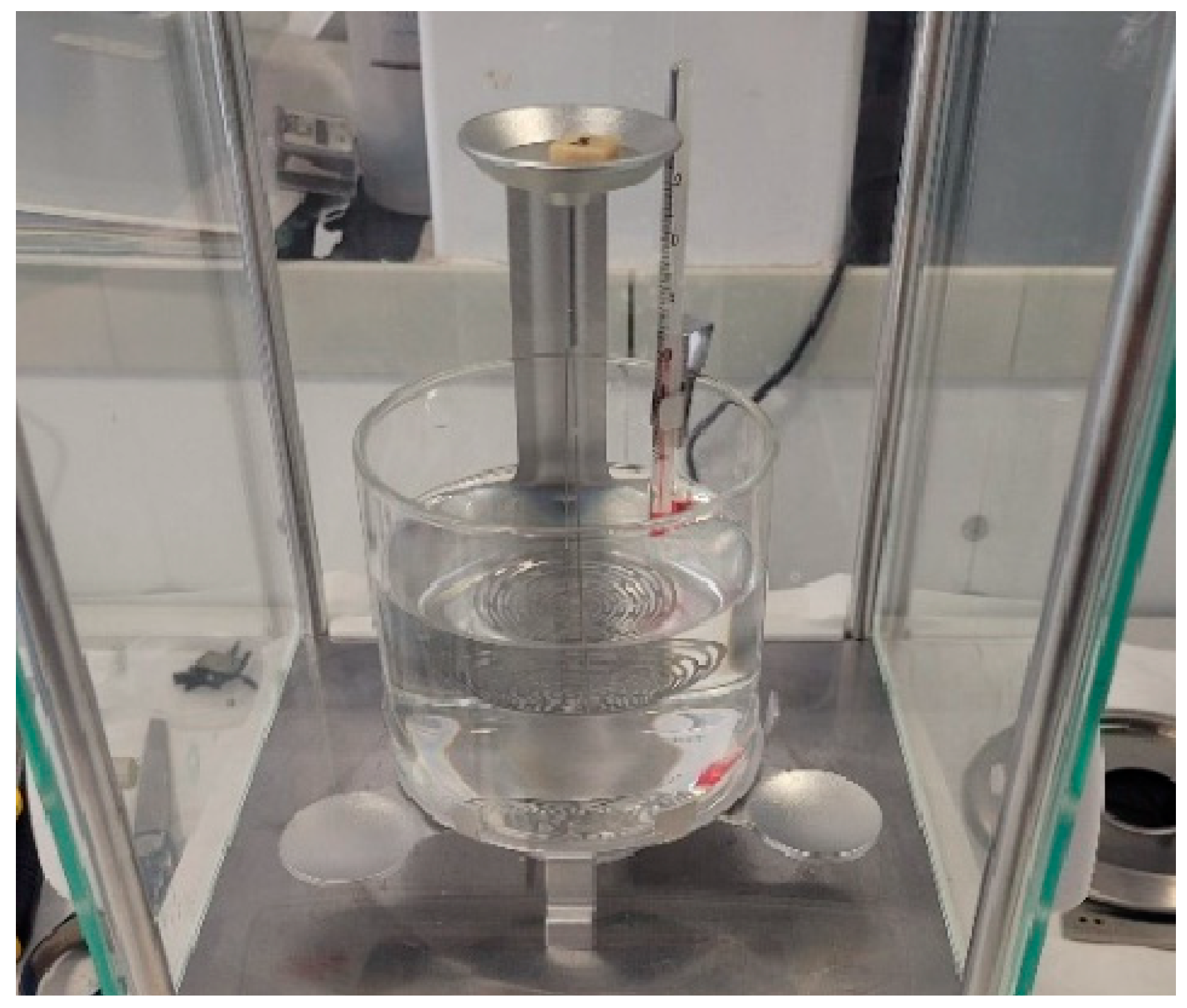
3.2.3. Density Measurements
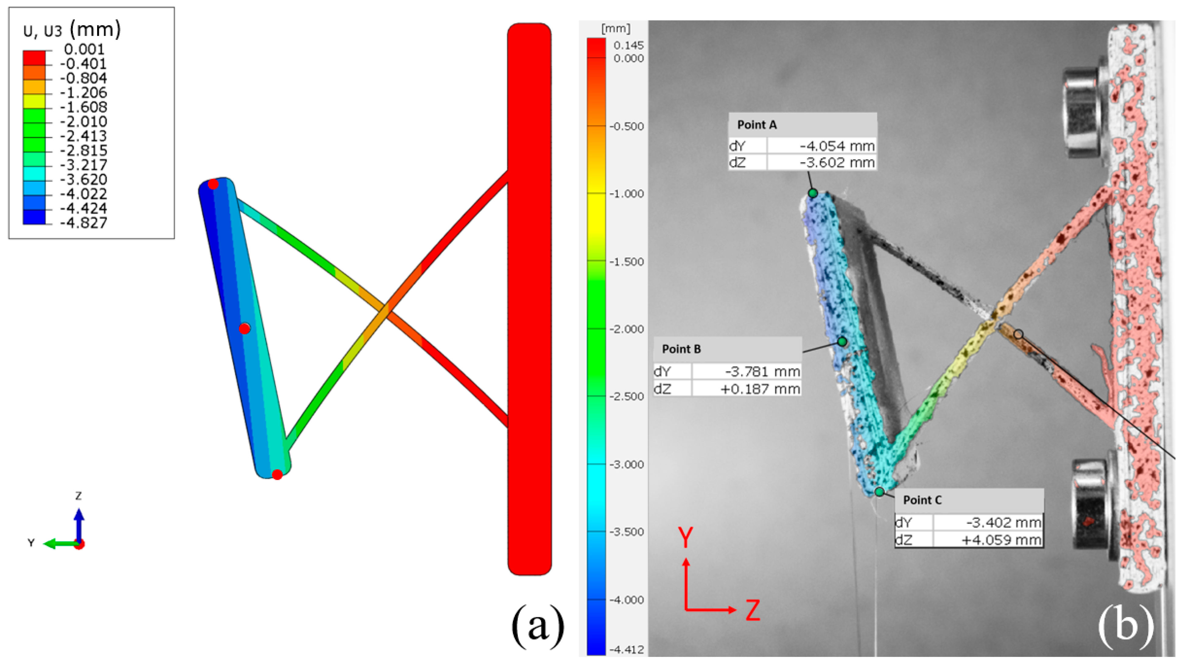
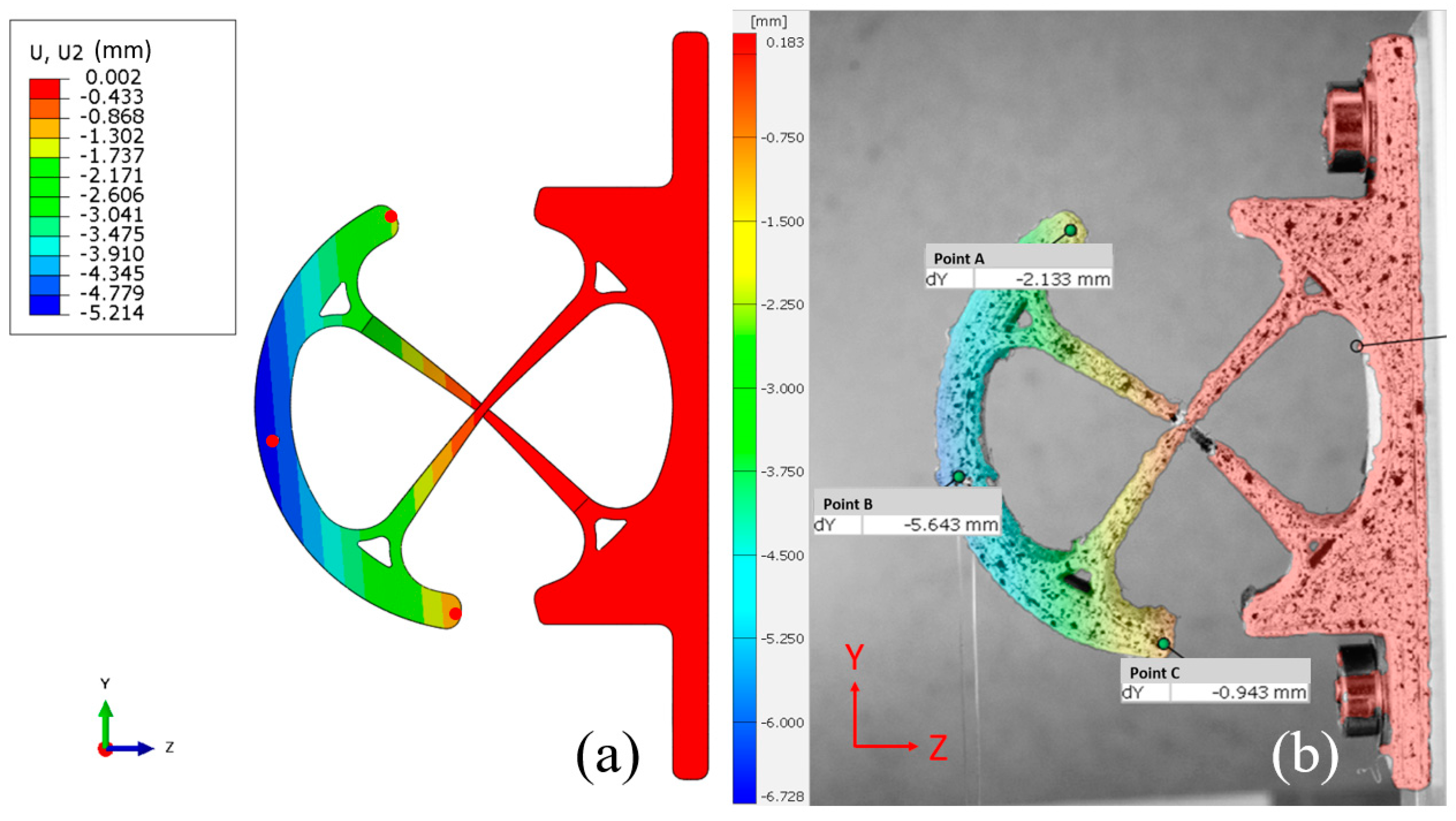
3.3. Finite Element Analysis and Experiment Correlation
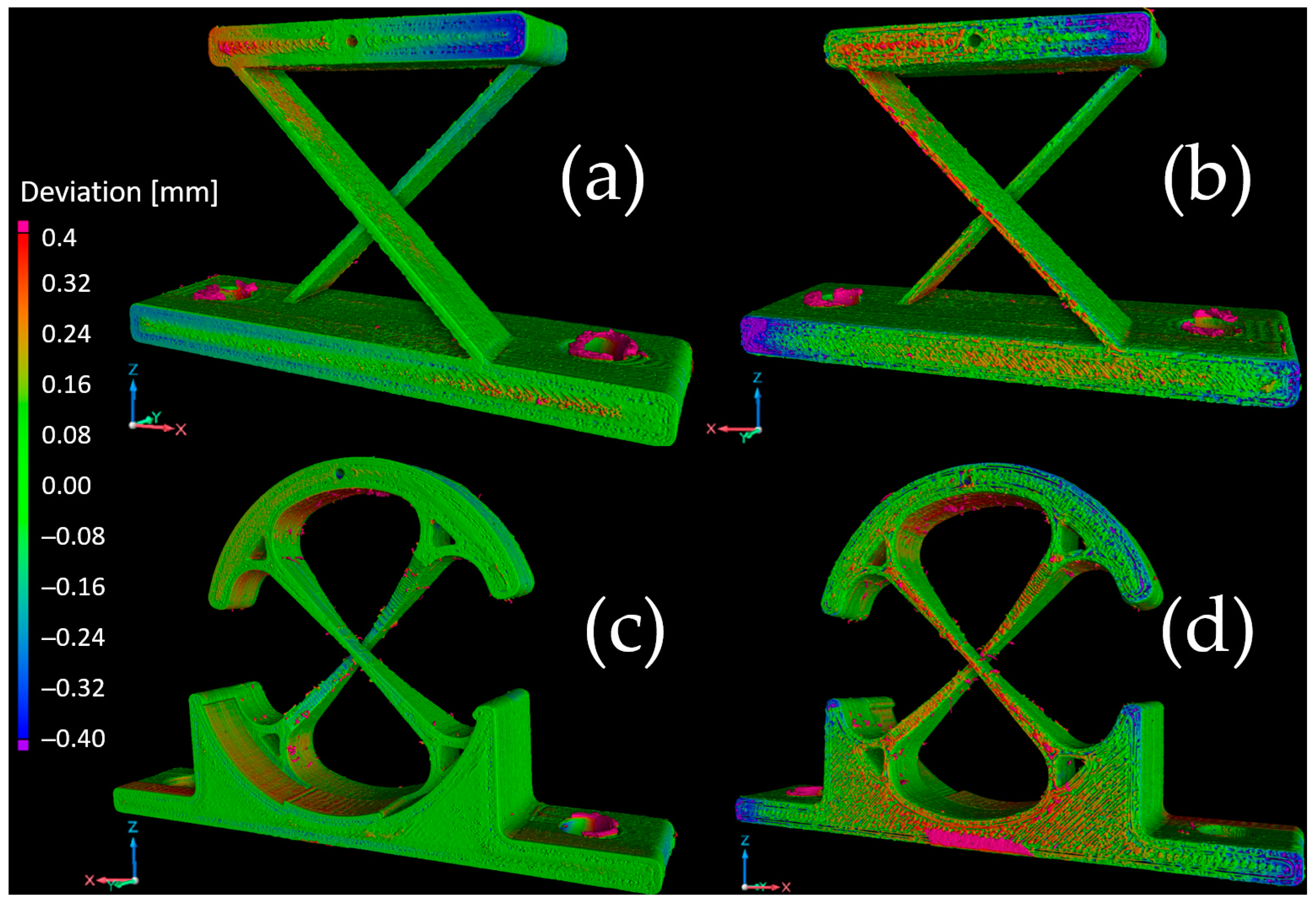
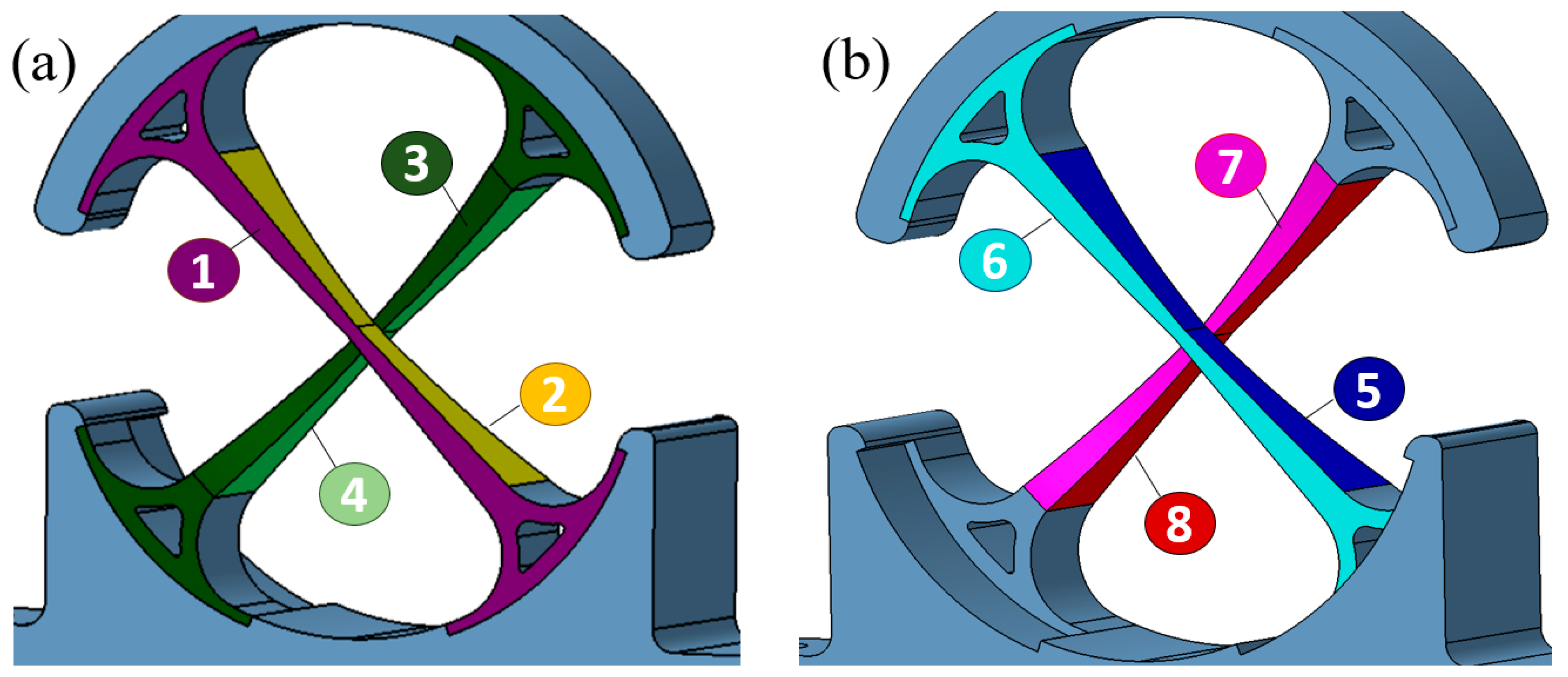
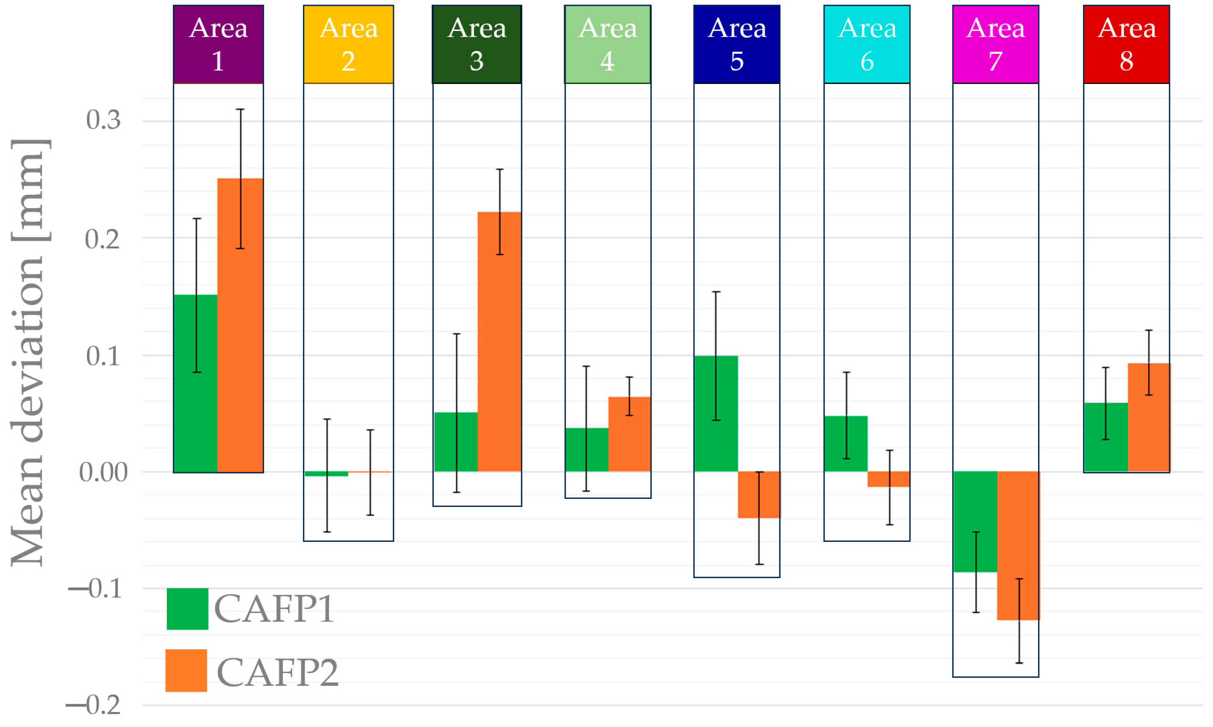
3.4. Metrology Analysis
4. Conclusions
Author Contributions
Funding
Data Availability Statement
Acknowledgments
Conflicts of Interest
Abbreviations
| DOF | Degree of freedom |
| CAFP | Cross-axis flexural pivot |
| PEKK | Polyetherketoneketone |
| PEEK | Polyetheretherketone |
| PLA | Poly(lactic acid) |
| FFF | Fused filament fabrication |
| TGA | Thermogravimetric analysis |
| DSC | Differential scanning calorimetry |
| FTIR | Fourier transform infrared |
| CAD | Computer-Aided Design |
List of Symbols
| Degree of crystallinity [%] | |
| Experimental melting enthalpy [J/g] | |
| Melting enthalpy of a 100% crystalline material [J/g] | |
| Enthalpy of crystallization [J/g] | |
| Tg | Glass transition temperature [°C] |
| Tc | Crystallization temperature [°C] |
| Tm | Melting temperature [°C] |
References
- Dearden, J.; Grames, C.; Jensen, B.D.; Magleby, S.P.; Howell, L.L. Inverted L-Arm Gripper Compliant Mechanism. J. Med. Devices 2017, 11, 034502. [Google Scholar] [CrossRef]
- Merriam, E.G.; Jones, J.E.; Magleby, S.P.; Howell, L.L. Monolithic 2 DOF Fully Compliant Space Pointing Mechanism. Mech. Sci. 2013, 4, 381–390. [Google Scholar] [CrossRef]
- Dang, M.P.; Le, H.G.; Van, M.N.; Chau, N.L.; Dao, T.-P. Modeling and Optimization for a New Compliant 2-Dof Stage for Locating Biomaterial Samples by an Efficient Approach of a Kinetostatic Analysis-Based Method and Neural Network Algorithm. Comput. Intell. Neurosci. 2022, 2022, 6709464. [Google Scholar] [CrossRef] [PubMed]
- Hao, G.; Yu, J.; Li, H. A Brief Review on Nonlinear Modeling Methods and Applications of Compliant Mechanisms. Front. Mech. Eng. 2016, 11, 119–128. [Google Scholar] [CrossRef]
- Jensen, B.D.; Howell, L.L. The Modeling of Cross-Axis Flexural Pivots. Mech. Mach. Theory 2002, 37, 461–476. [Google Scholar] [CrossRef]
- Dearden, J.; Grames, C.; Orr, J.; Jensen, B.D.; Magleby, S.P.; Howell, L.L. Cylindrical Cross-Axis Flexural Pivots. Precis. Eng. 2018, 51, 604–613. [Google Scholar] [CrossRef]
- Wu, J.; Cai, S.; Cui, J.; Tan, J. A Generalized Analytical Compliance Model for Cartwheel Flexure Hinges. Rev. Sci. Instrum. 2015, 86, 105003. [Google Scholar] [CrossRef] [PubMed]
- Corapi, D.; Morettini, G.; Pascoletti, G.; Zitelli, C. Characterization of a Polylactic Acid (PLA) Produced by Fused Deposition Modeling (FDM) Technology. Procedia Struct. Integr. 2019, 24, 289–295. [Google Scholar] [CrossRef]
- Wang, P.; Zou, B.; Ding, S.; Li, L.; Huang, C. Effects of FDM-3D Printing Parameters on Mechanical Properties and Microstructure of CF/PEEK and GF/PEEK. Chin. J. Aeronaut. 2021, 34, 236–246. [Google Scholar] [CrossRef]
- Hanon, M.M.; Dobos, J.; Zsidai, L. The Influence of 3D Printing Process Parameters on the Mechanical Performance of PLA Polymer and Its Correlation with Hardness. Procedia Manuf. 2021, 54, 244–249. [Google Scholar] [CrossRef]
- Forés-Garriga, A.; Pérez, M.A.; Gómez-Gras, G.; Reyes-Pozo, G. Role of Infill Parameters on the Mechanical Performance and Weight Reduction of PEI Ultem Processed by FFF. Mater. Des. 2020, 193, 108810. [Google Scholar] [CrossRef]
- Abeykoon, C.; Sri-Amphorn, P.; Fernando, A. Optimization of Fused Deposition Modeling Parameters for Improved PLA and ABS 3D Printed Structures. Int. J. Lightweight Mater. Manuf. 2020, 3, 284–297. [Google Scholar] [CrossRef]
- Zhen, H.; Zhao, B.; Quan, L.; Fu, J. Effect of 3D Printing Process Parameters and Heat Treatment Conditions on the Mechanical Properties and Microstructure of PEEK Parts. Polymers 2023, 15, 2209. [Google Scholar] [CrossRef] [PubMed]
- Battes, K.; Day, C.; Hauer, V. Outgassing Behavior of Different High-Temperature Resistant Polymers. J. Vac. Sci. Technol. A Vac. Surf. Film. 2018, 36, 021602. [Google Scholar] [CrossRef]
- Lafont, U.; Munck, M.; Wessing, J.; Terol-Sanchez, M.; Rampini, R. 3D Printing of Multifunctional Polymer for Space Application. In Proceedings of the 9th European Conference for Aeronautics and Space Sciences (EUCASS), Lille, France, 27 June–1 July 2022; p. 13. [Google Scholar] [CrossRef]
- Rinaldi, M.; Cecchini, F.; Pigliaru, L.; Ghidini, T.; Lumaca, F.; Nanni, F. Additive Manufacturing of Polyether Ether Ketone (PEEK) for Space Applications: A Nanosat Polymeric Structure. Polymers 2020, 13, 11. [Google Scholar] [CrossRef] [PubMed]
- Pérez-Martín, H.; Mackenzie, P.; Baidak, A.; Ó Brádaigh, C.M.; Ray, D. Crystallinity Studies of PEKK and Carbon Fibre/PEKK Composites: A Review. Compos. Part B Eng. 2021, 223, 109127. [Google Scholar] [CrossRef]
- Pedoto, G. Characterization and Modelling of the Thermomechanical and Ageing Behavior of PEKK and C/PEKK Composites for Aircraft Applications at High Temperatures (Above the Glass Transition Temperature); ISAE-ENSMA Ecole Nationale Supérieure de Mécanique et d’Aérotechique: Poitiers, France, 2020. [Google Scholar]
- Alqurashi, H.; Khurshid, Z.; Syed, A.U.Y.; Rashid Habib, S.; Rokaya, D.; Zafar, M.S. Polyetherketoneketone (PEKK): An Emerging Biomaterial for Oral Implants and Dental Prostheses. J. Adv. Res. 2021, 28, 87–95. [Google Scholar] [CrossRef] [PubMed]
- Cheng, K.; Shi, Z.; Wang, R.; Jiang, X.; Xiao, F.; Liu, Y. 3D Printed PEKK Bone Analogs with Internal Porosity and Surface Modification for Mandibular Reconstruction: An in Vivo Rabbit Model Study. Biomater. Adv. 2023, 151, 213455. [Google Scholar] [CrossRef] [PubMed]
- International Organization for Standardization ISO 527-1:2012; Plasics—Determination of Tensile Properties—Part 2: Test Conditions for Moulding and Extrusion Plastics. ISO: Geneva, Switzerland, 2012.
- International Organisation for Standardization ISO 178; Plastics—Determination of Flexural Properties. ISO: Geneva, Switzerland, 2006.
- International Organisation for Standardization ISO 1183-1; Plastics—Methods for Determining the Density of Non-Cellular Plastics—Part 1: Immersion Method, Liquid Pycnometer Method and Titration Method. ISO: Geneva, Switzerland, 2019.
- International Organisation for Standardization ISO 11357-1:2016(En); Plastics—Differential Scanning Calorimetry (DSC)—Part 1: General Principles. ISO: Geneva, Switzerland, 2016.
- Yahiaoui, M.; Chabert, F.; Paris, J.-Y.; Nassiet, V.; Denape, J. Friction, Acoustic Emission, and Wear Mechanisms of a PEKK Polymer. Tribol. Int. 2019, 132, 154–164. [Google Scholar] [CrossRef]
- Vasconcelos, G.d.C.; Mazur, R.L.; Botelho, E.C.; Rezende, M.C.; Costa, M.L. Evaluation of Crystallization Kinetics of Polymer of Poly (Ether-Ketone-Ketone) and Poly (Ether-Ether-Ketone) by DSC. JATM 2010, 2, 155–162. [Google Scholar] [CrossRef]
- Alexandre, M. Optimisation du Comportement Mécanique de Composites Structuraux PEKK/Fibres de Carbone par Ensimage Oligomères de PEKK; Université Toulouse 3 Paul Sabatier: Toulouse, France, 2017. [Google Scholar]
- Corbalan, N. Mechanical Performances of PEKK Thermoplastic Composites Linked to Their Processing Parameters; École Nationale Supérieure d’Arts et Métiers: Paris, France, 2017. [Google Scholar]
- Mngomezulu, M.E.; Luyt, A.S.; John, M.J. Morphology, Thermal and Dynamic Mechanical Properties of Poly(Lactic Acid)/Expandable Graphite (PLA/EG) Flame Retardant Composites. J. Thermoplast. Compos. Mater. 2019, 32, 89–107. [Google Scholar] [CrossRef]
- Xu, C.; Cheng, K.; Liu, Y.; Wang, R.; Xu, X. Effect of Processing Parameters on Flexural Properties of 3D-Printed Polyetherketoneketone Using Fused Deposition Modeling. Polym. Eng. Sci. 2021, 61, 465–476. [Google Scholar] [CrossRef]
- Nassir, N.A.; Birch, R.S.; Cantwell, W.J.; Wang, Q.Y.; Liu, L.Q.; Guan, Z.W. The Perforation Resistance of Glass Fibre Reinforced PEKK Composites. Polym. Test. 2018, 72, 423–431. [Google Scholar] [CrossRef]
- Lee, A.; Wynn, M.; Quigley, L.; Salviato, M.; Zobeiry, N. Effect of Temperature History during Additive Manufacturing on Crystalline Morphology of PEEK. Adv. Ind. Manuf. Eng. 2022, 4, 100085. [Google Scholar] [CrossRef]
- Antony Samy, A.; Golbang, A.; Harkin-Jones, E.; Archer, E.; McIlhagger, A. Prediction of Part Distortion in Fused Deposition Modelling (FDM) of Semi-Crystalline Polymers via COMSOL: Effect of Printing Conditions. CIRP J. Manuf. Sci. Technol. 2021, 33, 443–453. [Google Scholar] [CrossRef]
- Choupin, T.; Debertrand, L.; Fayolle, B.; Régnier, G.; Paris, C.; Cinquin, J.; Brulé, B. Influence of Thermal History on the Mechanical Properties of Poly(Ether Ketone Ketone) Copolymers. Polym. Cryst. 2019, 2, e10086. [Google Scholar] [CrossRef]
- Gan, D.; Lu, S.; Song, C.; Wang, Z. Morphologies, Mechanical Properties and Wear of Poly(Ether Ketone Ketone) (PEKK) and Its Composites Reinforced with Mica. Macromol. Mater. Eng. 2001, 286, 296–301. [Google Scholar] [CrossRef]
- Podsiadły, B.; Skalski, A.; Rozpiórski, W.; Słoma, M. Are We Able to Print Components as Strong as Injection Molded?—Comparing the Properties of 3D Printed and Injection Molded Components Made from ABS Thermoplastic. Appl. Sci. 2021, 11, 6946. [Google Scholar] [CrossRef]
- Lay, M.; Thajudin, N.L.N.; Hamid, Z.A.A.; Rusli, A.; Abdullah, M.K.; Shuib, R.K. Comparison of Physical and Mechanical Properties of PLA, ABS and Nylon 6 Fabricated Using Fused Deposition Modeling and Injection Molding. Compos. Part B Eng. 2019, 176, 107341. [Google Scholar] [CrossRef]
- Ding, S.; Zou, B.; Wang, P.; Ding, H. Effects of Nozzle Temperature and Building Orientation on Mechanical Properties and Microstructure of PEEK and PEI Printed by 3D-FDM. Polym. Test. 2019, 78, 105948. [Google Scholar] [CrossRef]
- Villefort, R.F.; Diamantino, P.J.S.; von Zeidler, S.L.V.; Borges, A.L.S.; Silva-Concílio, L.R.; Saavedra, G.; de Siqueira, F.A.; Tribst, J.P.M. Mechanical Response of PEKK and PEEK As Frameworks for Implant-Supported Full-Arch Fixed Dental Prosthesis: 3D Finite Element Analysis. Eur. J. Dent. 2021, 16, 115–121. [Google Scholar] [CrossRef]


| Diameter [mm] | 1.75 |
| ] | 1.291 |
| Tg [°C] | 159 |
| Tm [°C] | 308 |
| Layer thickness [mm] | 0.2 | Support height [mm] | 0.8 |
| Printing temperature [°C] | 345 | Support infill density [%] | 70 |
| Bed temperature [°C] | 145 | Support Z distance [mm] | 0.1 |
| Printing speed [mm/s] | 25 | Support type | triangular |
| Layer width [mm] | 0.4 | Support horizontal expansion [mm] | 0.5 |
| Flexural, Tensile, and Density Specimens | CAFPs | |
|---|---|---|
| Walls | 0 | 4 |
| Top/bottom layers | 0 | 5 |
| Infill type | ZigZag | Grid |
| Infill rate | 100% | 70% |
| Specimen | Flexural Modulus [MPa] | Flexural Strength [MPa] | Conventional Deflection (3.5% Strain) [mm] | Flexural Stress at Conventional Deflection [MPa] |
|---|---|---|---|---|
| F1 | 2200 | 94 | 5.5 | 72 |
| F2 | 2279 | 95 | 5.6 | 76 |
| F3 | 2289 | 97 | 5.6 | 76 |
| F4 | 2239 | 95 | 5.6 | 75 |
| F5 | 2276 | 99 | 5.5 | 76 |
| Mean value | 2266 | 96 | 5.6 | 75 |
| Standard deviation | 40 | 2.3 | 0.04 | 1.8 |
| Specimen | Flexural Modulus [MPa] | Flexural Strength [MPa] | Conventional Deflection (3.5% Strain) [mm] | Flexural Stress at Conventional Deflection [MPa] |
|---|---|---|---|---|
| F6 | 2526 | 108 | 5.2 | 80 |
| F7 | 2544 | 109 | 5.2 | 85 |
| F8 | 2610 | 112 | 5.2 | 86 |
| F9 | 2670 | 115 | 5.4 | 89 |
| F10 | 2657 | 115 | 5.4 | 88 |
| Mean value | 2601 | 112 | 5.2 | 86 |
| Standard deviation | 65 | 3.4 | 0.10 | 3.3 |
| Specimen | Young’s Modulus [MPa] | Tensile Strength [MPa] | Elongation at Break [%] |
|---|---|---|---|
| T1 | 2218 | 53 | 2.8 |
| T2 | 2795 | 50 | 2.5 |
| T3 | 2506 | 51 | 3.4 |
| T4 | 2950 | 48 | 2.2 |
| T5 | 2991 | 52 | 3.6 |
| Mean value | 2692 | 51 | 2.9 |
| Standard deviation | 326 | 1.7 | 0.6 |
| Specimen | Young’s Modulus [MPa] | Tensile Strength [MPa] | Elongation at Break [%] |
|---|---|---|---|
| T6 | 2892 | 69 | 4.1 |
| T7 | 2474 | 74 | 4.4 |
| T8 | 3420 | 68 | 4.0 |
| T9 | 3027 | 69 | 3.9 |
| T10 | 2351 | 71 | 4.5 |
| Mean value | 2833 | 70 | 4.2 |
| Standard deviation | 432 | 2.3 | 0.3 |
| AY | AZ | BY | BZ | CY | CZ | |
|---|---|---|---|---|---|---|
| Displacement test [mm] | −4.21 | −3.71 | −3.73 | 0.23 | −3.42 | 3.97 |
| Standard deviation [mm] | 0.27 | 0.27 | 0.29 | 0.06 | 0.19 | 0.20 |
| Displacement model [mm] | −4.55 | −3.99 | −3.93 | 0.19 | −3.31 | 4.36 |
| Difference | −8% | −7% | −5% | 17% | 3% | −10% |
| AY | AZ | BY | BZ | CY | CZ | |
|---|---|---|---|---|---|---|
| Mean distance test [mm] | −2.34 | −5.14 | −5.68 | 0.76 | −1.00 | 5.43 |
| Standard deviation [mm] | 0.09 | 0.31 | 0.10 | 0.29 | 0.06 | 0.31 |
| Distance model [mm] | −1.88 | −4.54 | −4.79 | 0.413 | −1.03 | 4.596 |
| Difference | 20% | 12% | 16% | 46% | −3% | 15% |
Disclaimer/Publisher’s Note: The statements, opinions and data contained in all publications are solely those of the individual author(s) and contributor(s) and not of MDPI and/or the editor(s). MDPI and/or the editor(s) disclaim responsibility for any injury to people or property resulting from any ideas, methods, instructions or products referred to in the content. |
© 2024 by the authors. Licensee MDPI, Basel, Switzerland. This article is an open access article distributed under the terms and conditions of the Creative Commons Attribution (CC BY) license (https://creativecommons.org/licenses/by/4.0/).
Share and Cite
Domerg, M.; Ostré, B.; Joliff, Y.; Grunevald, Y.-H.; Garcia, A.D. The Development of a 3D-Printed Compliant System for the Orientation of Payloads on Small Satellites: Material Characterization and Finite Element Analysis of 3D-Printed Polyetherketoneketone (PEKK). Aerospace 2024, 11, 294. https://doi.org/10.3390/aerospace11040294
Domerg M, Ostré B, Joliff Y, Grunevald Y-H, Garcia AD. The Development of a 3D-Printed Compliant System for the Orientation of Payloads on Small Satellites: Material Characterization and Finite Element Analysis of 3D-Printed Polyetherketoneketone (PEKK). Aerospace. 2024; 11(4):294. https://doi.org/10.3390/aerospace11040294
Chicago/Turabian StyleDomerg, Morgane, Benjamin Ostré, Yoann Joliff, Yves-Henri Grunevald, and Antoine Dubois Garcia. 2024. "The Development of a 3D-Printed Compliant System for the Orientation of Payloads on Small Satellites: Material Characterization and Finite Element Analysis of 3D-Printed Polyetherketoneketone (PEKK)" Aerospace 11, no. 4: 294. https://doi.org/10.3390/aerospace11040294