Abstract
This paper presents a concept for a universal tram driver console that has been developed based on research results regarding the review of tram control panels. These efforts were carried out as part of the project “Innovative training system for tram drivers, based on a full-cab simulator with the application of cognitive science” POIR.01.01.01-00-0135/22, with funding from the Smart Growth Operational Programme. This project involves the development of a tram driver training system based on a full-cabin tram simulator mounted on a motion platform, integrated with eye-tracking technologies and skin conductance response analysis for tram drivers’ assessment. The presented research results regarding the development of a universal control panel structure for a tram simulator have led to the creation of a panel based on interchangeable panels. The arrangement of individual switches was determined based on the identification, selection, critical evaluation, and analysis of data from current solutions.
1. Introduction
Dangerous incidents involving trams are classified as the phenomena with the most severe consequences. This is mainly due to the number of injured people, including tram passengers and other traffic participants, e.g., pedestrians, cyclists, and passengers of other vehicles. According to police reports, there were 149 accidents on trackways and railroad crossings in Poland in 2022, in which six people were killed and 217 injured. In 48 cases, the tram driver was to blame [].
Hazardous incidents in urban rail transportation can result from both technical and human factors. Training simulators contribute to improving rail transportation safety through their ability to increase the training level of drivers. The placement of switches on the console is significant in terms of mistakes made by drivers. Using a simulator-integrated driver evaluation tool based on data from cognitive measurement systems will make it possible to analyze a driver’s errors depending on the point of gaze focused on the control panel. The paper’s primary purpose is to present a universal control panel structure for a tram simulator based on interchangeable panels.
The structure of this paper includes in Chapter 2 a review of existing knowledge covering the use of simulators in training systems and an overview of existing solutions in rail transportation. Chapter 3 evaluates switch placement. Chapter 4 presents a solution for a universal console. Chapter 5 summarizes the achievements made.
2. State of the Art
This state-of-the-art review is divided into two parts. The first part focuses on using tram simulators in the transportation system. The second part focuses on the review of available solutions.
2.1. Tram Simulator
The development of urban rail transport is driven by the growing demand for public transport services []. In the first quarter of 2022, 16 tram transport operators operated 3118 trams in all Polish cities []. The expansion of tram networks, purchase of new vehicles, modernization of existing vehicles, and increase in passenger volume and traffic volume increase the risk of accidents []. Tram passengers [] and other traffic participants traveling on the streets [,,] bear the risk. Thus, the challenge for urban agglomerations is to ensure safe mobility. Improving safety in urban transportation is possible through appropriate training methods. Research on tram drivers’ perceptions of traffic safety challenges has indicated the need to improve the driver training program to reduce tram accidents [].
Increased safety is possible through the use of simulators, which create the right conditions to prepare for work and acquire the skills to cope with a changing environment []. The validity of using simulators as training tools has already been noted in the literature. The human factor identified in [] indicated that of the several ways to influence the human factor, education, and training are the main ways to influence drivers. The simulator developed by [] directly indicated a better transfer of practical skills than from printed materials in the study group analyzed. The benefits associated with the use of simulators in training systems are also related to the increase in safety by taking into account a variety of typical and atypical situations and are solutions characterized by lower operating and maintenance costs compared to the implementation of training on actual facilities [].
The key in the training aspect is to achieve an appropriate degree of replication of the actual system []. According to [], the degree of replication focuses on physical fidelity, functional fidelity, and behavioral accuracy. The physical fidelity of a simulator refers to the degree to which the simulator can replicate the physical feel, appearance, and sound in such a way that the user feels like he or she is participating in the natural system. The literature has already noted the relationship between simulator fidelity and the effectiveness of training delivered on simulators []. Functional fidelity focuses on replicating situations that could occur in a natural system []. Behavioral fidelity, on the other hand, focuses on mimicking real-social human interactions and reactions []. A review of validation studies of driving simulators indicates that the degree of replication of the natural system is also influenced by task, perceptual, and psychological fidelity []. Achieving an adequate degree of replication in training systems requires considering the responsibilities of vehicle drivers. In the case of tram drivers, these tasks are identified in [] and include tasks performed before undertaking a transportation task, a task performed during the ride, and after the ride is completed.
To improve safety and increase employee training, many transportation companies decided to purchase streetcar simulators []. This was determined by the increasing number of traffic incidents involving trams caused by young employees []. In Poland, we distinguish the following solutions:
- The NGT6 tram simulator developed by the Institute of Rail Vehicles at the Faculty of Mechanical Engineering, Cracow University of Technology (the first Polish tram simulator []), and the GT8S tram at the Museum of Urban Engineering;
- Tram simulator 105 Na of the company Polskie Symulatory at the Museum of Technology and Communication in Szczecin;
- 805N-ML tram simulator and Pesa Swing tram simulator by Polskie Symulatory in Lodz, Poland;
- Konstal 105N2k/2000 tram simulator by Lander in Warsaw;
- Tram simulator Moderus Beta MF 24 AC by Lander in Wroclaw.
The above solutions are static simulators, which do not allow studying the driver’s state and visual focus points depending on the training scenario. Some systems allow studying stress levels or fatigue []. According to [], the stress level in drivers directly impacts their work performance and, thus, safety. The authors attempted to quantify drivers’ stress levels and the factors contributing to them through an experimental study conducted in a realistic railroad simulator. Extensive statistical analysis showed that short-term heart rate variability indicators can differentiate between different stress levels. The paper [] presents changes in the autonomic nervous system and driving style modifications in response to incremental stimulation of stress levels during simulated car driving. The first stress load involved the random delivery of mechanical stimuli to the vehicle during calm highway driving via a series of sudden and unexpected skids. The second stress load meant an incremental psychological load consisting of arithmetic questions with time pressure added to the mechanical stimuli. Driver physiological signals and vehicle mechanical parameters were recorded and analyzed throughout the experimental session. In [], the mental load associated with increased driving speed was assessed from 60 km/h to 180 km/h. A car driving simulator was used for this. The evaluation was based on changes in facial temperature. The subjects showed an increase in the difference between the temperature of the nose and forehead, a decrease in the level of skin potential, and an increase in the level of skin conductance. The authors [] examined the effects of time pressure on eye movement, pupil diameter, cardiovascular and respiratory activity, driving performance, vehicle control, limb movement, and head position. Based on existing theories of human behavior under time pressure, three categories of results were distinguished: driving speed, physiological measurements, and driving strategies. Drivers showed increased heart rate, increased respiratory rate, increased pupil diameter, and decreased eye blink rate. In [], study participants participated in one of two simulated train driving scenarios. Both were monotonous and differed only in the level of cognitive preparation required. Monotony is an inherent feature of transportation industries, including rail, air, and road transport, which can have a negative impact on safety.
Since driving a tram is a complex and very demanding task [], studying the focus points of drivers’ eyes while driving is essential, especially on the control panel and the environment []. In the publication [], a study of the gaze focus of motorists with different experiences while driving on a tram simulator was conducted. The results show differences in attentional dynamics between different user groups. Novices focused more on the center panel of the tram simulator than experts. In [], drivers’ use of the emergency brake was analyzed. Combined with the results of a survey of experts, the use of the emergency brake was tested depending on its location on the control panel. The test used a simulator and an actual vehicle. The interpretation of individual switches on the tram control panel can be associated with incidents, resulting in selecting the wrong direction of travel []. The article [] describes incidents caused by the diversity of rolling stock and the low experience of new employees. It has been observed that inexperienced drivers, combined with stress and fatigue, have difficulty adjusting to different tram pulpits. Most operators have vehicles in their fleet that differ in their control panels.
The training solutions on the market need products with the high degree of immersion that full-cab simulators placed on motion platforms have. The specific structure of the tram cab is based on large glass windows with contoured arches in the close vicinity of the driver. This is an essential issue for constructing a simulator on a traffic platform regarding image projection. Currently, tram simulators mainly use console designs, in which the image is projected onto a flat external screen, or compact simulators, which are usually displayed on several independent monitors. According to [], the level of immersion (the degree of user involvement in the virtual reality experience) is low in such a case. It is also essential to equip the simulator with an integral trainee assessment system, using data from cognitive eye-tracking and a GSR (galvanic skin response) skin galvanometer to measure the level of stress and intensity of emotions experienced []. This makes it possible, among other things, to analyze a motorist’s errors depending on the point of gaze, focus on the control panel and the environment, and study his emotions in these situations.
2.2. An Overview of Available Solutions
A selection, critical evaluation, and comparative analysis of the tram control panel of modern trams that Polish transport companies operate have been conducted. Eleven vehicles were selected from different cities, including line and prototype vehicles. The review presented concerns only trams in operation in Poland.
The first vehicle is a Poznan-based Solaris Tramino S105p. It is a fully low-floor, articulated tram consisting of five sections. The overall length of the vehicle is 32.026 mm, while the width of the tram body is 2.4 m. Solaris Tramino S105p trams are equipped with wide doors—the double ones offer 1500 mm of passage width. The tram driver’s console consists of three sections: the right-hand panel, the center panel, and the left-hand panel. In addition, three buttons and one switch have been placed on the right armrest.
The next tram is the Pesa Swing 122NaŁ—a five-unit, single-space, and fully low-floor tram. The tram is 30.5 long and adapted to run on a narrow-gauge track with a width of 1000 mm. The tram is manufactured for Lodz. The body of the vehicle is based on three non-torsional bogies. The extreme bogies under the end members (one and five) are drivable, while the middle bogie under member three is rolling. The driver’s console on the 122NaŁ tram consists of three sections. Right, center, and left console. In addition, two buttons and one switch were placed in the lower right section.
Another tram is the Moderus Gamma LF 06 AC, manufactured for Lodz—a five-unit, 32.5-meter-long tram based on four traction bogies. The tram is 88% low floor. The high floor is located only within the first and last bogie. All passenger doors are accessible from the low floor, whose height above rail head level is 350 mm directly at the door. All bogies on the tram are drive bogies; the outermost bogies are torsion bogies (allowable steering angle of 10°), while the middle bogies are stiffened bogies (torsion within a range of not more than 1°). The tram driver’s console consists of three sections: the right-hand panel, the center panel, and the left-hand panel. In addition, three buttons and one switch have been placed on the right armrest.
The next tram is Moderus Beta MF 02 AC. It is a three-member design based on four rotating bogies. These trams are used in cities such as Poznan, Szczecin, Wroclaw, Grudziadz, and the Silesian Agglomeration. A total of more than 150 Beta trams were produced for Polish cities. The tram console has three sections: right, left, and center sections. The center section contains the most relevant buttons, controls, and a speedometer. In addition, there is a side console on the left side, used mainly for starting the tram.
The following vehicle is Moderus Gamma LF 01 AC—a five-unit low-floor tram based on three two-axle rigid bogies. Two bogies are drive bogies, and one (the middle one) is a rolling bogie. This is a prototype vehicle leased by MPK Poznan from Modertrans. The console consists of three panels: the left panel, the right panel, and the center panel. Each panel has both buttons and a screen (touchscreen or, for example, monitoring view).
The following vehicle is Moderus Gamma LF 02 AC/LF 03 AC BD—a low-floor, three-unit tram, 32 m long, based on four bogies, running in Poznan. LF 02 AC version is a one-way vehicle, and LF 03 AC BD is a two-way tram. Apart from the directionality, the vehicles are almost identical and have analogous driver’s cabs. The console consists of three main panels—left, right, and the center panel. The left panel is equipped with a monitoring preview. The center panel is the screen with the parameters of the vehicle. The passenger information system was placed on the right panel, in addition to the switches. Currently, more than 100 Gamma trams have been produced.
Another vehicle is the Moderus Beta MF10AC—a single-unit, partially low-floor tram equipped with two powered bogies operated by Silesian Trams. The vehicle has three doors to the passenger area. Access to the driver’s cab is through the passenger space. The driver’s console consists of three main panels. On the side console on the left is an additional panel with twelve buttons, and on the right armrest is a small panel duplicating the buttons found on the main dashboard.
The following vehicle is Moderus Beta LF05AC—a single-unit, fully low-floor prototype vehicle equipped with two powered torsion bogies. Other equipment on this tram includes an ultra-modern SIC technology drive, air conditioning for the driver’s cab, and a heat pump for the passenger space. The driver’s console consists of three sections. In addition, there are additional button strips under the right and left panels. Buttons are also located on the right armrest of the driver’s seat.
Another tram is Moderus Gamma LF 07 AC—a 32-meter-long three-unit tram, based on four bogies, operated in Wroclaw, and completely low floor—the floor height above the level of the rail head is 350 mm at the doors and 520 mm above the bogies. MOSFETs made of silicon carbide (SiC) transistors are used in the drive devices. The console consists of three main sections—the right-hand panel, the center panel, and the left-hand panel. The side panel was also placed on the left. A function panel was placed on the right armrest of the driver’s seat.
The next vehicle is a low-floor, five-member, one-way Skoda 16T tram. The tram has two end sections, two inset sections, and a center section. The end members are belted on two-axis bogies, each driven by two asynchronous traction motors that always form a single motor unit. The center section fits on a two-axle rolling carriage. The tram had undergone a significant repair at SAATZ in 2021 and is in service in Wroclaw. The driver’s console is divided into three main sections: left, center, and right. In the center section, in addition to the on-board computer, are the most crucial function buttons.
The last vehicle analyzed is the Moderus MF 17 AC. It was created due to a deep modernization of the Protram 205WrAs tram. It is a 28-meter-long three-member vehicle based on four bogies, operated in Wroclaw. The tram is partially low floor (the low floor located in the middle section accounts for 23% of the total floor area). The driver’s console on the MF 17 AC tram is divided into three parts: left, center, and right. The right part is a passenger information system. In the center section are the on-board computer and the most essential buttons. On the left is a radio station and a switch used less frequently.
Based on a review of available solutions, the driver’s console was divided into the areas indicated in Figure 1.
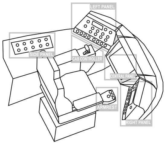
Figure 1.
Areas of the tram console.
The basic console is divided into right, left, and central panels. The central panel in each type of vehicle includes an on-board computer that monitors current vehicle parameters. Depending on the type of tram, the right and left panels are interchangeable with each other and contain, among other things, a passenger information computer, switches responsible for controlling doors, lighting, heating, windshield wipers, and selecting the direction of travel. In the armrest are duplicated switches most often used by tram drivers. These are, in many cases, turn signals and opening/closing doors. On the other hand, the side panel is equipped with switches used infrequently, such as those required to start the tram or take action in the event of tram damage. Each vehicle’s driving controller is located on the left side. This controller allows starting, coasting, service braking, and emergency braking. In addition, in many cases, it is equipped with an external bell switch.
3. Evaluation of the Arrangement of Switches
Trams are tailor-made vehicles, which means that each ordering party in the description of the subject of the contract defines all the parameters of the vehicle, its layout, number of sections, bogies, equipment, etc. The arrangement of buttons and switches on the driver’s console is similar. In most cases, the final deployment of individual consoles, sections, and buttons is part of the dialogue between the employer and the contractor. This is a group of several people who make significant decisions subjectively. In many cases, drivers or depot facilities staff are also invited to this dialogue. Therefore, in carrying out the present work, the authors included a group of experts in order to design and build a universal console as objectively as possible. Only such an approach guarantees the expected result. To evaluate individual drivers’ consoles, we invited a broad group of drivers, i.e., people who operate a tram for several hours every day and who should have a decisive vote on the layout of buttons and switches on individual panels.
The consoles and buttons of 11 modern trams operated by Polish transport companies were evaluated by 30 experts, including employees of carriers, vehicle manufacturers, and design engineers. Among the users, the evaluation was carried out directly by motormen (a total of twenty people, among whom were four driving instructors), depot maintenance workers (two shunters), and technical facilities specialists (three people). Among the vehicle manufacturer’s experts were vehicle commissioning personnel (two people), while among engineers, the evaluations were made by people with experience in trams’ mechanical and electrical design (three people).
The largest group of experts making the assessment were the direct users of trams, i.e., the drivers who operate the vehicles. This group was very diverse—of them, 55% were women (divided into two age categories: those aged 21–40 accounted for 40% in the women’s group and those aged 41–60 accounted for 60% in the women’s group, respectively) and 45% were men (divided into two age categories: those aged 21–43 accounted for 53% in the men’s group and those aged 44–65 accounted for 47% in the men’s group, respectively). Professional experience in operating trams among the selected entire group of drivers is as follows: 0–5 years of experience, 20%; 5–10 years of experience, 30%; 10–20 years of experience, 40%; and the group with more than 20 years of experience accounted for 10%.
Such a wide and varied group of experts made it possible to obtain an evaluation from many different points of view. Evaluating only the driver who uses the vehicle is critical; however, it may give a partial assessment. The additional opinion of designers who have repeatedly designed consoles for various carriers is also of great value. Back-office employees who have repeatedly determined the arrangement of buttons on desktops in many new and modernized vehicles also know much about the subject under analysis.
The tram driver console and its buttons were evaluated based on four criteria:
- Safety—the location of crucial buttons related to vehicle safety in easily accessible areas was considered.
- Functionality—functionality was understood as placing buttons most frequently used by the driver during the ride closer to his hands in better accessible locations than buttons used infrequently.
- Legibility—understood as adequate description and marking of buttons so that their function and location can be understood and read without any doubt.
- Complementarity—considers the logic of the location of buttons—whether the buttons of a given group, responsible for similar functions, are located close to each other.
Each expert filled out a button evaluation questionnaire, assigning a rating for each switch location on a scale of 0–5 for the 11 analyzed trams operated by Polish transport companies. The ratings were then summed up, and based on the highest ones, the default button locations on the universal panel were selected, which can be changed between slots. It is worth mentioning that only Polish trams were evaluated. The maximum total score for a single criterion is 150 points, and the maximum score for a switch on the dashboard is 600 points. Table 1 presents sums of ratings of switch locations on a console for five selected vehicles.

Table 1.
Sums of ratings of switch locations on a console for five selected vehicles.
Based on the sum of the ratings in Table 2, the default location of the following switches was selected for the Skoda 16T tram: battery, direction of travel, bell, activation of passenger switches, door opening, door closing, front door, and location of the passenger information computer. In terms of the listed switches, this tram received the highest score among the 11 evaluated. The total score for the switch is as follows: the battery is 546.5 points, the direction of travel is 546 points, the bell is 571.5 points, the passenger switch activation is 589.5 points, the door opening is 592.5 points, door closing is 591.5 points, the front door is 593, and passenger information computer location is 592 points. It comprises partial scores considering safety, functionality, legibility, and complementarity. Blank rows in the table mean there was no such switch in a particular type of tram.
Table 2.
Switch evaluations for the Skoda 16T tram.
4. Universal Console for Tram Drivers
Based on the analysis of the performed assessments, it was concluded that the optimal solution would be to design the consoles of the driver’s console in such a way that the individual sections of the switches are located next to each other (complementarity)—for example, switches that perform door functions, exterior lighting, or directional selection and turn signals. Another conclusion of the analysis is placing the switches used most often as close to the right hand as possible. An important issue that experts pointed out was the legibility of switch markings. In the universal driver console, descriptive icons are unambiguous, simple, and easy to read for everyone.
An important aspect that has been realized is the issue of the interchangeability of individual panels and the possibility of swapping them in place. This relies on the fact that the upper panels can be swapped between each other and the lower quadruple panels as well. For example, the passenger information and monitoring control computer on the right panel will be on the left panel after the swap. The situation is similar on the lower small panels with switches. Each is identical and features four switches. This allows these four panels to be freely interchanged in four different slots. This provides many possible switch arrangements that can be easily and quickly obtained.
The developed console consists of three main large panels and four small panels under the side main panels. A panel on the side console complements this. Figure 2 shows the arrangement of panels in the shell of the console. Table 3 describes the functions of each button on each panel.
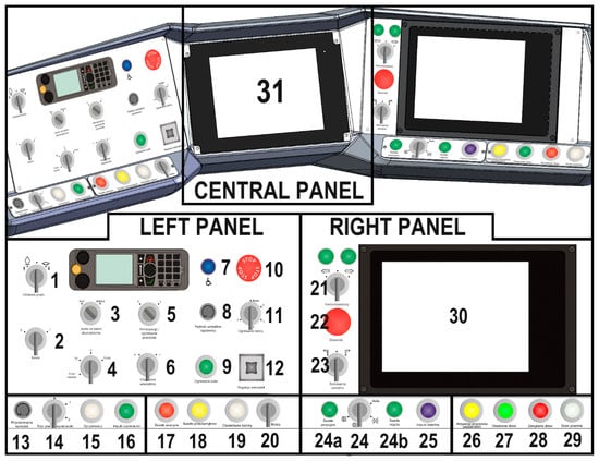
Figure 2.
Universal console visualization.
Table 3.
Functionality of the switches of the universal driver’s console with interchangeable panels.
The distribution of individual switches in selected Polish trams and the developed universal console are presented in Table 4. Table 4 uses the following designations: LP—left panel; RP—right panel; CP—central panel; SC—side console; DR—driving range finder. One prototype vehicle has an additional panel with buttons under the ceiling above the control console, so it is designated as a UCP—upper console panel—in the table. In Table 4, the first abbreviation indicates the selected location of the button. In contrast, the second abbreviation (after the slash) indicates that the consoles are interchangeable concerning each other so that at any time, the part can be in a different location—total versatility.
Table 4.
Location of switches in selected Polish trams and universal tram driver console.
For example, the location of the switch responsible for heating the driver’s cabin was rated highest for the Moderus Gamma LF 07 AC tram (Table 2), so in the developed universal console, the heating of the cabin switch was placed on the left side of the panel (as shown in Table 4).
The lower right panel was placed with a section of switches responsible for wide-ranging functions related to opening and closing the door. In all of the analyzed tram driver’s consoles examined in Poland, the door switches were the closest to the driver’s right hand. The choice of this location was driven by the need for quick access to these switches and the fact that the drivers are using this section most often. In the developed simulator, the door switches have been placed in the console of the right armrest of the driver’s seat for increased travel comfort and to minimize the time the driver spends activating, opening, or closing the door. Other rail vehicle manufacturers use a similar solution, also indicated in this paper, including PESA Bydgoszcz, Solaris, and Modertrans Poznan. The group of door switches was particularly highly rated by experts in the Skoda 16T RK tram and Moderus Gamma LF 01 AC; because of that, a similar layout was used and presented in the article. The section of switches related to directional selection and the turn signals have been located in one section near the driver’s right hand. The section is additionally equipped with indicator lights that inform about the given state of the switch. Due to complementarity, the indicated elements were located close to each other. These are switches that are also frequently used by the driver tram. In addition, the analysis indicated that this is the best location for them. Similar switch placement can be found in Moderus MF 17 AC or Solaris Tramino trams. Each manufacturer placed the turn signal switch on the right panel as close to the driver’s right hand. The direction selector and the switch responsible for it in the indicated vehicles were also near the turn signal switch. It should be noted that, depending on the direction of the travel system, this function is performed by a single switch (such as the system from MPK Wroclaw) or a group of switches (MPK Poznan).
Based on an expert assessment, a passenger information computer was placed on the right-hand panel. The analysis showed that the right panel should have a passenger information computer. This computer provides phonic and graphical information on the performance of transport tasks to passengers. In most cases analyzed, these functions were performed by 10” panels/autocomputers, and these devices were located on the right-hand panels. However, there were vehicles (from MPK Poznan) where the SIP computer was placed on the left-hand panel. With this in mind, a technical solution was developed to change the location of the SIP computer from the right-hand panel to the left-hand panel. Experts pointed out that placing the SIP computer on the right-hand side of the panel is the most functional solution—the trams that received the most points were the Moderus MF 17 AC, Moderus Gamma LF 07 AC, and PESA Swing 122NaŁ.
The left-hand side of the lower right-hand console has been encased by switches performing the vehicle’s external lighting functions. These include the light pulse, the switch for the position, low- and high-beam headlights, and the auto function. This location is determined by the need for quick access and the high frequency of use of these switches. However, given that the switching of external lighting can be fully automatic, requiring no intervention or supervision by the driver, this section could be interchanged with the door switch section and even with the lower panels of the left-hand panel (a group of switches used occasionally). The final recipient of this solution can thus define the order. An analysis of the experts’ results shows that this is the right place for these switches—high scores in this respect were given to twin solutions such as the Moderus Gamma LF 05 AC. A switch to activate the bell was placed in the central part of the left side of the right console. This switch has a much larger diameter of the touch part, colored red. Such a solution is confirmed by analyzing the arrangement of pushbuttons in other tram consoles used in Poland. The choice of such a location was dictated by the results of the driver’s console development analysis in the vehicles operated by Polish carriers. The location in Skoda 16T RK and Moderus Gamma LF 07 AC streetcars received the most points.
The tram’s central computer was built into the center of the driver’s panel. It is the primary device of an extensive diagnostic system and is used to display the information presented in Table 3. The default image on the panel is the main screen, which contains all basic diagnostic information. Menu and error screens are also available. In the analyzed trams, the driver’s auto computer was also located in the central part of the tram driver’s console.
On the left-hand large panel, a group of switches is responsible for starting the vehicle and the driving mode. This group includes the battery activation switch, the pantograph raises and a lower button, the forward or reverse selector switch, or from the maneuvering panel, battery or main driving mode switch. The location of this group of switches follows directly from the analysis of existing solutions. These are usually located on the left side of the console or the side panel, which is also usually on the left side. This panel also placed a group of switches responsible for heating and air conditioning the passenger compartment and the driver’s cabin. A red emergency brake switch is placed in the upper right of the panel. This location ensures excellent visibility of this critical switch and perfect ergonomics for both right- and left-handers. On the left panel are switches responsible for mirror settings and a light indicating the use switch for disabled persons. A radio is also placed on this panel for communication between the motorist and dispatcher. On the lower left side of the console are two narrow panels with four switches each. On the first panel from the left are the switches for the wiper and washer operation, as well as a knob to adjust the brightness of the backlighting of the switches and controls throughout the console. The second narrow panel features switches to activate the emergency lights, fog lights, driver’s cab lights, and a switch to adjust the sunblind. This is a group of switches that are important but far less frequently used—such a regularity was noted in expert evaluations of Moderus Beta MF 02 AC, Gamma LF 02 AC, Moderus Gam-ma LF 07 AC, Moderus MF 17 AC trams.
On the left side of the console is an additional panel with switches that are rarely used in regular operation and are only found in some cities. The side console panel includes switches related to the operation of the door system, namely activation of the timed door closure, locking the last section door, and driving lock with the door open. A PLC-free emergency drive actuation switch and a brake release switch are still located on this panel. The armrest of the driver’s seat contains the switches most often used by the driver: door control and turn signals.
5. Conclusions
The market lacks training solutions for tram drivers mounted on a motion platform. Such simulators have a much higher degree of immersion than simulators with an external computer system or compact simulators. According to the project concept, a universal control panel structure was developed. The proposed solution is aimed at general tram driving lessons based on their basic functionality rather than the panel layout of a specific model. The panel structure of the tram driver’s console makes it possible to obtain a console that coincides with the driver’s requirements without interfering with the entire structure of the simulator.
The distribution of individual switches was determined based on the identification, selection, critical evaluation, and comparative analysis of the consoles of tram driver consoles of modern trams operated by Polish transport companies. In addition, swapping panels with switches between each other within the slots available in the console shell is possible. The simulator is integrated into a driver assessment tool based on cognitive eye-tracking data and a GSR skin galvanometer to measure stress levels and the intensity of emotions experienced. Eye tracking allows studying the eyes’ focus on specific console elements and the environment.
The accumulated data presented in the article provide a basis for further research. In further stages of the research work, the authors will focus on developing a fuzzy logic evaluation model for any driver’s console. The implementation of such a model and then its verification in a simulator with interchangeable desktops can increase the safety and efficiency of the operations performed by drivers.
Author Contributions
Conceptualization, A.K. and Ł.W.; methodology, A.K. and Ł.W.; validation, M.K., Ł.B., D.B. and P.W.; formal analysis, Ł.W. and E.M.; investigation, M.K., Ł.B., D.B. and P.W.; writing—original draft, Ł.W. and A.D.; writing—review & editing, A.K., Ł.W. and A.D.; visualization, E.M.; Supervision, A.K.; project administration, ŁW. All authors have read and agreed to the published version of the manuscript.
Funding
The article is based on research carried out as part of the project “Innovative training system for tram drivers, based on a full-cab simulator with the application of cognitive science” (POIR.01.01.01-00-0135/22).
Data Availability Statement
Data are contained within the article.
Conflicts of Interest
The authors declare that they have no known competing financial interests or personal relationships that could have appeared to influence the work reported in this paper.
References
- Symon, E.; Rzepka, P. Wypadki Drogowe w Polsce w 2022 Roku, 1st ed.; Owsiewski, P., Ed.; Wydział Opiniodawczo-Analityczny Biura Ruchu Drogowego Komendy Głównej Policji: Warsaw, Poland, 2023. [Google Scholar]
- Yang, H.; Liang, Y. Examining the Connectivity between Urban Rail Transport and Regular Bus Transport. Sustainability 2023, 15, 7644. [Google Scholar] [CrossRef]
- Górnikiewicz, W. Zmiany w Strukturze Taboru Komunikacji Tramwajowej w Polsce w Latach 2004–2022. Stud. BAS 2022, 27–57. [Google Scholar] [CrossRef]
- Seidl, J. The Influence of the Construction of Tram Fronts on the Consequences of Accidents with Passenger Cars. Acta Polytech. CTU Proc. 2023, 43, 93–105. [Google Scholar] [CrossRef]
- Kobaszyńska-Twardowska, A.; Gill, A.; Firlik, B. Zdarzenia Niebezpieczne z Udziałem Tramwajów. Autobusy Tech. Eksploat. Syst. Transp. 2016, 17, 256–260. [Google Scholar]
- Guo, Y.; Liu, Y.; Xiao, H.; Ye, J. Explore the Collision Safety of Tram and Passenger Vehicle under Disparate Right of Way. In Proceedings of the SPIE—The International Society for Optical Engineering, Guangzhou, China, 23–25 September 2023; Volume 12591. [Google Scholar]
- Lackner, C.; Heinzl, P.; Leo, C.; Klug, C. Investigations on Tram-Pedestrian Impacts by Application of Virtual Testing with Human Body Models. Eur. Transp. Res. Rev. 2023, 15, 22. [Google Scholar] [CrossRef]
- Schröter, B.; Hantschel, S.; Huber, S.; Gerike, R. Determinants of Bicycle Crashes at Urban Signalized Intersections. J. Saf. Res. 2023, 87, 132–142. [Google Scholar] [CrossRef]
- Tanvir, S.; Habib, N.Z.; Walker, G.H. Investigation of Dubai Tram Safety Challenges and Road User Behavior through Tram Driver’s Opinion Survey; Springer: Berlin/Heidelberg, Germany, 2020; Volume 964, ISBN 9783030205027. [Google Scholar]
- Olsson, N.; Lidestam, B.; Thorslund, B. Effect of Train-Driving Simulator Practice in the European Rail Traffic Management System: An Experimental Study. Transp. Res. Rec. 2023, 2677, 694–706. [Google Scholar] [CrossRef]
- Nalmpantis, D.; Naniopoulos, A.; Bekiaris, E.; Panou, M.; Gregersen, N.; Falkmer, T.; Naten, G.; Dols, J. “Trainer” Project: Pilot Applications for the Evaluation of New Driver Training Technologies; Elsevier: Amsterdam, The Netherlands, 2005; pp. 141–156. ISBN 0-08-044379-6. [Google Scholar]
- Quan, C.Y.; Mansor, S.; Jian, C.J.; Rahman, M.M.; Karim, H.A.; Weng, B.K. Modelling and Evaluation of Driving Simulator for Driving Education in Malaysia. J. Logist. Inform. Serv. Sci. 2023, 10, 211–220. [Google Scholar] [CrossRef]
- Górowski, M.; Ozon, T. Zastosowanie Pierwszego Polskiego Symulatora Tramwaju w Procesie Szkoleń i Badań Naukowych. Probl. Kolejnictwa 2017, 174, 29–37. [Google Scholar]
- Roberts, A.P.J.; Stanton, N.A.; Plant, K.L.; Fay, D.T.; Pope, K.A. You Say It Is Physical, I Say It Is Functional; Let Us Call the Whole Thing off! Simulation: An Application Divided by Lack of Common Language. Theor. Issues Ergon. Sci. 2020, 21, 507–536. [Google Scholar] [CrossRef]
- Olsson, N. A Validation Study Comparing Performance in a Low-Fidelity Train-Driving Simulator with Actual Train Driving Performance. Transp. Res. Part F Traffic Psychol. Behav. 2023, 97, 109–122. [Google Scholar] [CrossRef]
- Dahlstrom, N.; Dekker, S.; Van Winsen, R.; Nyce, J. Fidelity and Validity of Simulator Training. Theor. Issues Ergon. Sci. 2009, 10, 305–314. [Google Scholar] [CrossRef]
- Winter, J.; Wieringa, P.; Dankelman, J.; Mulder, M.; Van Paassen, M.M. Driving Simulator Fidelity and Training Effectiveness. In Proceedings of the 26th European Annual Conference on Human Decision Making and Manual Control, Lyngby, Denmark, 25–27 June 2007. [Google Scholar]
- Mullen, N.; Charlton, J.; Devlin, A.; Bedard, M. Simulator Validity: Behaviors Observed on the Simulator and on the Road. In Handbook of Driving Simulation for Engineering, Medicine and Psychology; CRC Press: Boca Raton, FL, USA, 2011; pp. 1–18. [Google Scholar]
- Wynne, R.A.; Beanland, V.; Salmon, P.M. Systematic Review of Driving Simulator Validation Studies. Saf. Sci. 2019, 117, 138–151. [Google Scholar] [CrossRef]
- Pałęga, M. Ocena Ryzyka Zawodowego Stanowisku Pracy Motorniczego Tramwaju. Eksploatacja 2017, 24, 188–193. [Google Scholar]
- Dadashi, N.; Scott, A.; Wilson, J.R.; Mills, A. Rail Human Factors: Supporting Reliability, Safety and Cost Reduction, 1st ed.; Dadashi, N., Scott, A., Wilson, J.R., Mills, A., Eds.; CRC Press: London, UK, 2013; ISBN 9780203759721. [Google Scholar]
- Kozlowski, R.; Stanik, K. Security Management in Urban Logistics Using a Tram Driving Simulator in MPK Łódź. Przedsiębiorczość I Zarządzanie 2019, 20, 39–53. [Google Scholar]
- Górowski, M.; Rogacewicz, T. Symulator Tramwaju–NGT6K. TTS Tech. Transp. Szyn. 2014, 9, 19–22. [Google Scholar]
- Tavakoli, A.; Lai, N.; Balali, V.; Heydarian, A. How Are Drivers’ Stress Levels and Emotions Associated with the Driving Context? A Naturalistic Study. J. Transp. Health 2023, 31, 101649. [Google Scholar] [CrossRef]
- Jiao, Y.; Sun, Z.; Fu, L.; Yu, X.; Jiang, C.; Zhang, X.; Liu, K.; Chen, X. Physiological Responses and Stress Levels of High-Speed Rail Train Drivers under Various Operating Conditions—A Simulator Study in China. Int. J. Rail Transp. 2023, 11, 449–464. [Google Scholar] [CrossRef]
- Lanatà, A.; Valenza, G.; Greco, A.; Gentili, C.; Bartolozzi, R.; Bucchi, F.; Frendo, F.; Scilingo, E.P. How the Autonomic Nervous System and Driving Style Change with Incremental Stressing Conditions During Simulated Driving. IEEE Trans. Intell. Transp. Syst. 2015, 16, 1505–1517. [Google Scholar] [CrossRef]
- Kajiwara, S. Evaluation of Driver’s Mental Workload by Facial Temperature and Electrodermal Activity under Simulated Driving Conditions. Int. J. Automot. Technol. 2014, 15, 65–70. [Google Scholar] [CrossRef]
- Rendon-Velez, E.; van Leeuwen, P.M.; Happee, R.; Horváth, I.; van der Vegte, W.F.; de Winter, J.C.F. The Effects of Time Pressure on Driver Performance and Physiological Activity: A Driving Simulator Study. Transp. Res. Part F Traffic Psychol. Behav. 2016, 41, 150–169. [Google Scholar] [CrossRef]
- Dunn, N.; Williamson, A. Driving Monotonous Routes in a Train Simulator: The Effect of Task Demand on Driving Performance and Subjective Experience. Ergonomics 2012, 55, 1008–1997. [Google Scholar] [CrossRef]
- Tzouras, P.; Farah, H.; Papadimitriou, E.; Oort, N.; Hagenzieker, M. Tram Drivers’ Perceived Safety and Driving Stress Evaluation. A Stated Preference Experiment. Transp. Res. Interdiscip. Perspect. 2020, 7, 100205. [Google Scholar] [CrossRef]
- Naweed, A.; Rose, J.; Singh, S.; Kook, D. Risk Factors for Driver Distraction and Inattention in Tram Drivers. In Proceedings of the AHFE 2016 International Conference on Human Factors in Transportation, Lake Buena Vista, FL, USA, 27–31 July 2017. [Google Scholar]
- Warchoł-Jakubowska, A.; Krejtz, I.; Krejtz, K. An Irrelevant Look of Novice Tram Driver: Visual Attention Distribution of Novice and Expert Tram Drivers. In Proceedings of the Eye Tracking Research and Applications Symposium (ETRA), Tübingen, Germany, 30 May 2023; Association for Computing Machinery: New York, NY, USA, 2023. [Google Scholar]
- Callari, T.C.; Moody, L.; Mortimer, M.; Stefan, H.; Horan, B.; Birrell, S. “Braking Bad”: The Influence of Haptic Feedback and Tram Driver Experience on Emergency Braking Performance. Appl. Ergon. 2024, 116, 104206. [Google Scholar] [CrossRef]
- Currie, G.; Reynolds, J.; Logan, D.; Young, K.L. “Tram Wrong Way” International Experience and Mitigation of Track Switch Errors. Transp. Res. Rec. 2023, 2677, 631–643. [Google Scholar] [CrossRef]
- Callari, T.C.; Mortimer, M.; Moody, L.; Seyedmahmoudian, M.; Lewis, R.; Horan, B. Smooth and Safe Tram Journeys: Tram Driver Perspectives and Opportunities Using a Haptic Master Controller in a Virtual Reality Environment. Ergonomics 2022, 65, 445–466. [Google Scholar] [CrossRef] [PubMed]
- Narciso, D.; Melo, M.; Rodrigues, S.; Paulo Cunha, J.; Vasconcelos-Raposo, J.; Bessa, M. A Systematic Review on the Use of Immersive Virtual Reality to Train Professionals. Multimed. Tools Appl. 2021, 80, 13195–13214. [Google Scholar] [CrossRef]
- Jiang, A.; Gong, Y.; Yao, X.; Foing, B.; Allen, R.; Westland, S.; Hemingray, C.; Zhu, Y. Short-Term Virtual Reality Simulation of the Effects of Space Station Colour and Microgravity and Lunar Gravity on Cognitive Task Performance and Emotion. Build. Environ. 2023, 227, 109789. [Google Scholar] [CrossRef]
Disclaimer/Publisher’s Note: The statements, opinions and data contained in all publications are solely those of the individual author(s) and contributor(s) and not of MDPI and/or the editor(s). MDPI and/or the editor(s) disclaim responsibility for any injury to people or property resulting from any ideas, methods, instructions or products referred to in the content. |
© 2024 by the authors. Licensee MDPI, Basel, Switzerland. This article is an open access article distributed under the terms and conditions of the Creative Commons Attribution (CC BY) license (https://creativecommons.org/licenses/by/4.0/).