Abstract
The damage evolution process of layered rock is influenced by its fine structure, lamination direction, and confining pressure, exhibiting significant anisotropic characteristics. This study focuses on shale as the research object, employing indoor tests and theoretical analysis to define damage variables and initial damage based on ultrasonic wave velocity. This research investigates the damage evolution law of layered rock under varying confining pressures and dip angles. The findings reveal that damage variables defined using transverse wave velocity effectively reflect the damage evolution process. Additionally, confining pressure significantly affects damage evolution, with increasing pressure causing a rightward shift in the damage variable–strain curve and an increase in initial damage. The slab inclination angle also influences damage evolution; samples with 45° and 60° inclinations are more susceptible to damage, with initial damage showing a trend of increasing and then decreasing. To accurately describe the relationship between damage variables and strain during the loading process, this paper establishes a segmented damage evolution equation characterized by wave velocity. Initially, an inverse proportional function is employed to characterize the strain before crack closure. Subsequently, a logistic function represents the curve from crack strain to peak strain. This combined approach provides a comprehensive depiction of the damage evolution. This study underscores the importance of considering confining pressure and laminar inclination in the analysis of rock stability and integrity. These results provide critical insights into the damage evolution characteristics of layered rocks, offering valuable references for engineering safety assessments.
1. Introduction
As a natural material, rocks exhibit random distributions of various internal defects. The deterioration of a rock’s macroscopic mechanical properties due to changes in these internal defects under external loads and environmental conditions is termed damage [1,2]. The propagation of microcracks is often seen as a process of damage accumulation in rocks, ultimately leading to their macroscopic destruction [3,4,5,6,7]. The deformation and damage mechanisms of laminated rock bodies are influenced by the rock’s fine structure, the orientation of laminations, and ambient pressure, resulting in significant anisotropy [8,9]. Changes in local stress and storage environment further complicate the damage characteristics and mechanisms of layered rock [10,11,12,13].
Therefore, understanding the damage evolution process of layered rock masses is crucial for engineering stability control and safety prediction.
In recent years, numerous scholars have conducted theoretical and experimental studies on the damage evolution process of layered rock bodies. Tian et al. [6] and Luo et al. [14] performed impact tests on shale, using the HJC model to define damage variables and establishing a finite element model that considers confining pressure and inclination angle. Cheng et al. [7] used digital imaging techniques to investigate the time damage evolution of laminated hard sandstone. Bai et al. [15] defined an intrinsic model of layered rock damage characterized by a second-order tensor, verified through numerical simulations. Li et al. [1] conducted biaxial loading tests on layered sandstones with a 15° dip angle, analyzing the statistical damage evolution considering lateral pressure. Song et al. [16] examined the relationship between the critical damage and laminar inclination angle of laminated sandstone under cyclic loading, analyzing the change in fatigue sensitivity with laminar inclination angle. Liu et al. [17] explored the effect of laminar inclination on the damage evolution of yellow sandstone based on energy dissipation, establishing a uniaxial damage principal model with logistic function to account for initial damage.
Currently, research on rock damage has advanced significantly, and these studies have laid a solid foundation for analyzing the damage–deformation–destruction process of layered rocks, employing a diverse array of tools and methods. At the macroscopic scale, numerous damage variables have been established to characterize the evolution of rock damage. These variables can be derived from experimental measurements, statistical analyses, or geometric damage theories. However, despite the progress, existing damage variables for rocks exhibit certain limitations. The primary issue lies in the fact that the definition and description of initial damage remain unclear. To avoid negative damage, it is essential to define a suitable initial damage that reflects pre-existing defects or those present at the onset of external force application [18,19,20].
Zhao et al. [21,22] modeled the acoustic properties and damage evolution of rocks under loaded conditions, defining the longitudinal wave velocity of rocks under unloaded conditions as the initial damage. Wang et al. [23] used elastic longitudinal wave velocity to define initial damage and analyze the damage evolution process of surrounding rock during excavation. Yang et al. [24] defined initial damage using acoustic emission ringing counts as a covariate to study the damage process of layered composite rocks under uniaxial compression. In summary, defining the initial damage of rock based on ultrasonic wave velocity effectively reflects its damage evolution characteristics [25]. However, this approach primarily focuses on longitudinal wave velocity at specific moments during loading or stressing, without examining real-time wave velocity changes. To address this gap by studying shale, this paper defines damage variables and initial damage based on ultrasonic transverse wave velocity and analyzes the anisotropic properties of shale through indoor experiments and theoretical analysis. It investigates the damage evolution of laminated rock using wave velocity characterization based on initial damage and develops corresponding damage evolution equations. This research explores the damage evolution law of layered rock under varying confining pressures and inclination angles, providing important references and evaluation bases for the damage evolution characteristics of layered rock bodies and engineering safety issues.
2. Methods
2.1. Samples
The slate specimens used in this test were taken from an exploration flat at a pumped storage power station in Huangyang Town, Wuwei City (Gansu, China). The samples were taken from the southern part of the project area, Silurian gray slate, at a depth of approximately 400 m. The natural stress field values were approximately σ1 = 8.4–16.8 MPa, σ2 = 10.9–14.3 MPa, and σ3 = 5.2–9.9 MPa and showed an increasing trend with depth. All samples were from the same rock mass with no obvious cracks or other defects. The samples are well developed with little weathering, and the lithology is relatively uniform with high integrity, which is convenient for the sampling, handling, and preparation of standard specimens.
To meet the test requirements, the samples were drilled at various angles from the collected blocks. Six groups of samples were prepared with stratigraphic inclination angles (β) of 0°, 30°, 45°, 60°, 75°, and 90°, ensuring that each group was extracted from the same block (Figure 1a). According to established regulations, a core drilling machine was used to machine the slate into a standard cylindrical specimen of 50 mm × 100 mm; the parallelism of the two end faces was greater than 98%. The flatness and inclination of the end faces of the rock samples were meticulously controlled in strict accordance with the specifications (Figure 1b).
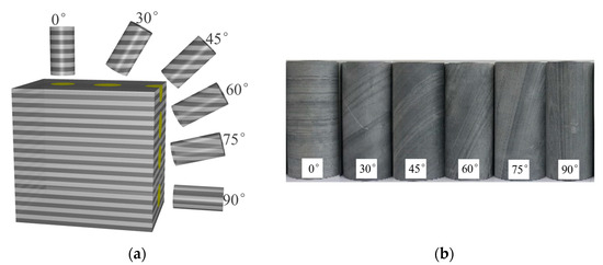
Figure 1.
(a) Sketch of sample coring method and (b) shale samples with different laminar inclination angles.
2.2. Experimental Setup
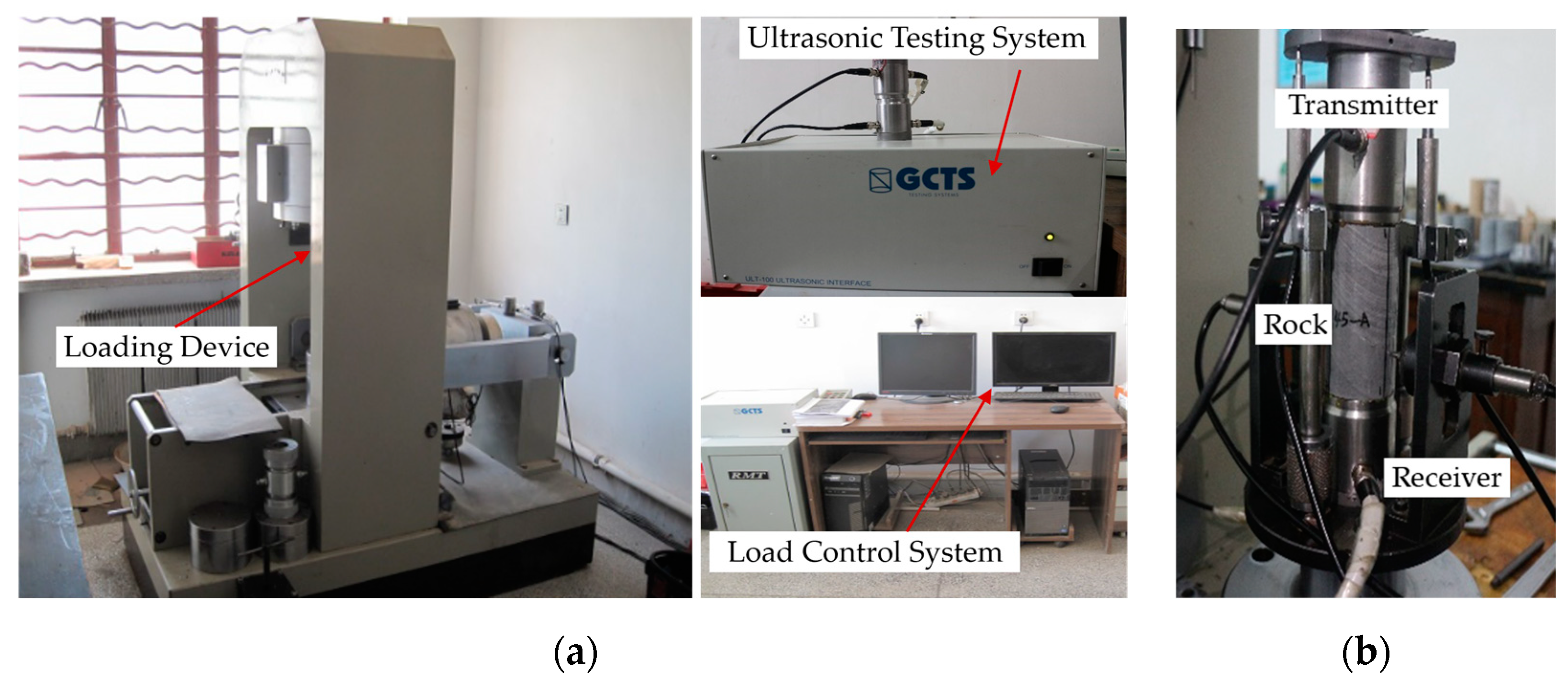
The RMT-301 testing machine (Figure 2a), developed by the Wuhan Geotechnical Institute of the Chinese Academy of Sciences, and the ULT-100 ultrasonic testing system, developed by the GCTS Company of the United States, were employed for the stress wave velocity test.
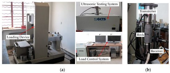
Figure 2.
(a) RMT-301 testing machine and ULT-100 ultrasonic testing system and (b) triaxial loading test.
The test system is a computer-controlled, multifunctional electro-hydraulic servo stiffness tester with the advantages of easy operation, high measurement accuracy, and strong protection function, which can effectively monitor the instantaneous damage of brittle rock, and it is suitable for a variety of mechanical tests, such as uniaxial compression, triaxial compression, shear, indirect tensile, and rheological tests of rock. It uses a high-speed pulse transmitter and an ultra-high-speed analog-to-digital converter to excite and store acoustic signals, with a sampling rate of up to 20 MHz and as low as 156 Hz. It can be manually controlled in real time by software and can be used in manual mode to determine unloaded wave velocity and in automatic mode to automatically acquire acoustic wave data under load.
To minimize the impact of random errors, two specimens were selected for uniaxial compression tests at each laminar inclination. During triaxial loading, the confining pressures were set to 5 MPa, 10 MPa, and 20 MPa. These pressure values were chosen to correspond with the ground stresses at the source location of the specimens.
2.3. Experimental Method
The specimens underwent conventional uniaxial and triaxial loading tests, followed by stress wave velocity tests. To minimize random error, two specimens were selected for uniaxial compression testing for each laminar inclination. During triaxial loading, the confining pressure was set to 5 MPa, 10 MPa, and 20 MPa, corresponding to the ground stress values at the specimen source location.
For the triaxial loading tests, each specimen was placed in a triaxial pressure chamber and connected to the triaxial pressure source (Figure 2b). Both axial and confining pressures were applied at a synchronized rate until the target confining pressure was reached. Subsequently, the confining pressure was maintained constant while the axial pressure was increased at a rate of 0.2 kN/s until the specimen failed.
3. Results
3.1. Defining Damage Variables and Initial Damage
The internal state variables of a rock that change during the damage process and affect its mechanical behavior are known as the rock’s damage variables. However, the definition of these damage variables is not uniform. They are defined in various ways, including elastic constants, yield stress, density, ultrasonic velocities, and acoustic emission. Among these variables, ultrasonic wave velocity has several advantageous qualities. Firstly, it causes minimal damage to the rock, thus reducing potential errors. Secondly, it is a technique that can be easily repeated, minimizing the likelihood of inconsistency. Thirdly, the required equipment is relatively simple and straightforward to operate. Fourthly, the data obtained from this technique are stable and easy to process. Therefore, ultrasonic wave velocity is regarded as an effective means of defining damage variables and initial damage.
Assuming the rock is an isotropic body comprising a rock matrix and microcracks, the propagation of ultrasonic waves in the rock medium follows the law of elastic wave propagation. Consequently, the stress–strain constitutive equation, expressed by the displacement of the rock unit, can be derived.
is the Laplace operator; ρ is the density of the medium; e is the volumetric strain; G is the Ramey coefficient, G = E/(1 + 2μ); and λ is the Ramey coefficient, λ = μE/[(1 + μ)(1 + 2μ)].
In an elastic medium, the displacement U = (u, v, w) at any point satisfies Equation (1). In setting u = u(x, t), v = 0, and w = 0 and substituting into Equation (1), the longitudinal wave velocity expression can be obtained.
Setting u = 0, v = 0, and w = w(x, y) yields the transverse wave velocity expression
According to Lemaitre’s strain equivalence principle, rock damage can be represented by the damage variable D [26]. When the rock is considered an isotropic elastic damage material, the constitutive equation follows the theory of damage mechanics of continuous media.
E0 is the modulus of elasticity in the undamaged state; D is the damage variable; and E is the post-damage modulus of elasticity.
Therefore, the damage variable for the rock can be derived as
From Equations (2) and (3), the elastic modulus can be characterized by longitudinal or transverse wave velocity, and since the transverse wave is more sensitive to the performance of damage variations within the rock, Equation (3) is transformed and substituted into Equation (5) to derive an expression for the damage variable based on the characterization of the transverse wave velocity
DV is the damage variable based on VS; VS is the transverse wave velocity of the damaged rock; and VSf is the transverse wave velocity of the intact undamaged rock.
From Equation (6), the damage variable characterized by the wave velocity takes values in the range [0, 1]; when VS = VSf, DV = 0, the rock is internally intact and undamaged, and when VS = 0, DV = 1, the rock is damaged.
Since some residual strength exists in some specimens, which still makes the value of the damage variable change after the macroscopic damage of the specimen occurs, only the stage before peak intensity is considered in the calculation of the damage variable based on the wave velocity, and the damage of the specimen is considered to have occurred when the stress is loaded to the peak intensity of the specimen and DV = 1.
For the initial damage existing inside the natural rock, according to the change rule of microfracture inside the rock under external loading, when the stress level reaches the crack closure stress, the fracture inside the rock is completely closed, and the intactness of the specimen is maximized, so it can be approximated that the corresponding crack closure wave speed VSc at this time is the transverse wave speed of the intact and undamaged damage VSf. Therefore, by substituting the initial transverse wave velocity of the rock specimen, VS0, into Equation (5), the initial damage D0 of the rock can be quantitatively expressed.
D0 is the initial damage of the rock; VS0 is the initial transverse wave speed of the rock; and VSc is the crack closure wave speed of the rock.
3.2. Damage Evolution Behavior
The process of laminar rock transitioning from integrity to fragmentation under loading is essentially a process of damage evolution. Quantifying this damage evolution using ultrasonic waves can accurately reveal the mechanical properties of the rock. This quantification also holds significant implications for predicting and providing early warnings of instability in related projects. To evaluate the damage evolution process and characteristics of laminated rock, this study examines two key variables: the damage variable (DV) and the initial damage (D0). The influence of these variables on the evolution process is analyzed from two perspectives: ambient pressure and the inclination angle of the laminated rock body.
3.2.1. Effect of Confining Pressure on Damage Evolution
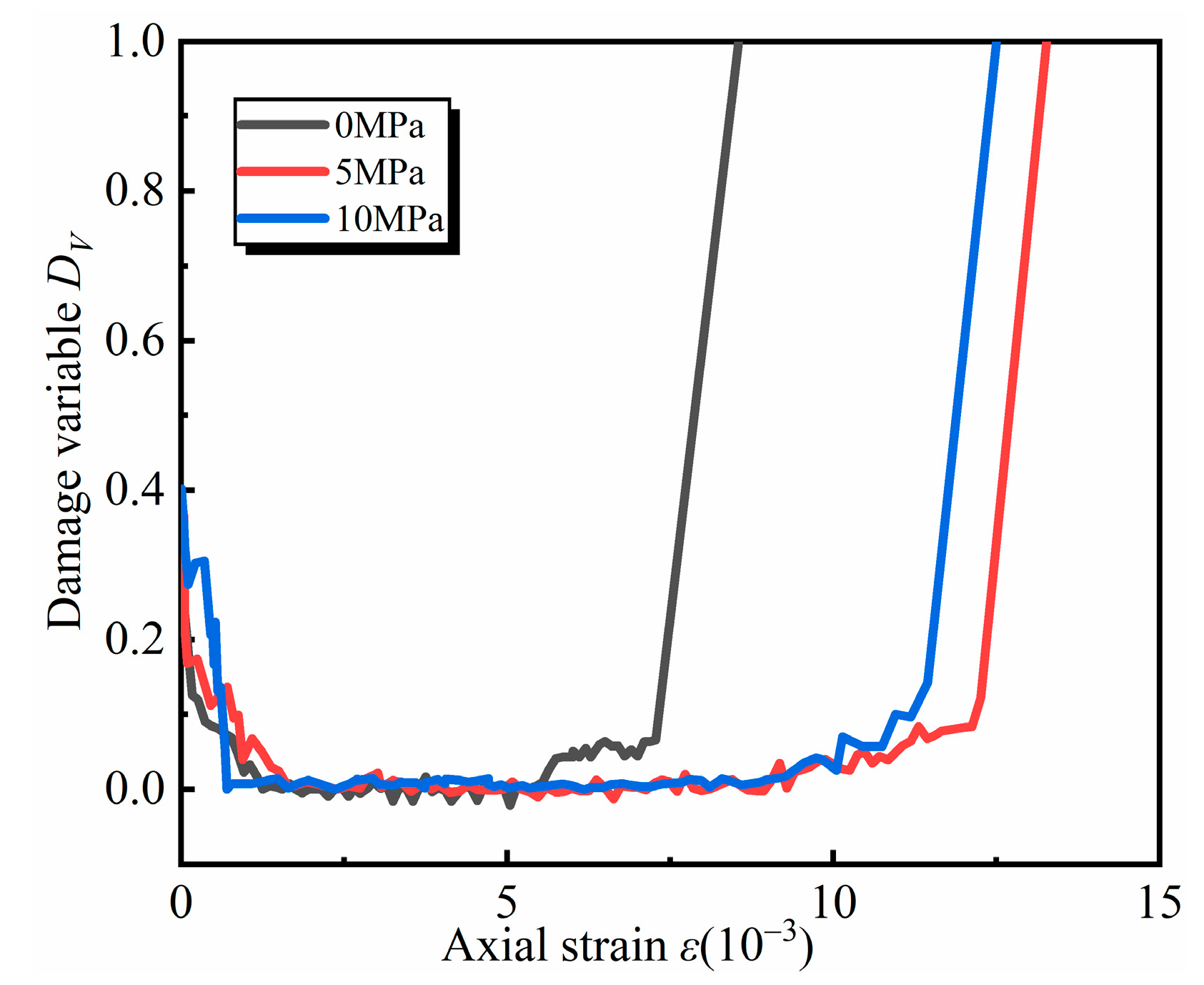
Taking the specimen with a laminar inclination of 0° as an example, the evolution of the damage variable (DV) of rock specimens with the same inclination under different confining pressure loading is illustrated in Figure 3. When the inclination angle is constant, the DV-ε curve of the specimen shifts to the right as confining pressure increases. This shift indicates a more pronounced stage of slow damage rise. For specimens with the same inclination, a higher confining pressure corresponds to a larger strain value for the same damage value. This suggests that confining pressure exerts a binding effect on the deformation of the rock specimen, inhibiting the development of new microfractures and controlling damage progression. Consequently, greater axial deformation is required to produce the same damage under higher confining pressure.

Figure 3.
The effect of perimeter pressure on the evolutionary process of the damage variable DV.
As confining pressure increases, the initial damage of specimens with the same inclination also increases. The rate of change of the DV-ε curve during the damage decline stage becomes larger. This is because higher confining pressure increases the crack closure wave velocity, causing microfractures within the rock to close faster and the wave velocity growth rate to accelerate. Additionally, the increase in confining pressure significantly enhances the damage during the slow rise stage, while the overall rate of change of the curve decreases gradually during the rapid rise stage. This phenomenon occurs because confining pressure promotes the development of plastic deformation in the specimen, weakening its brittle characteristics and making the trend of wave speed decline more evident.
3.2.2. Effect of Joints Inclinations on Damage Evolution
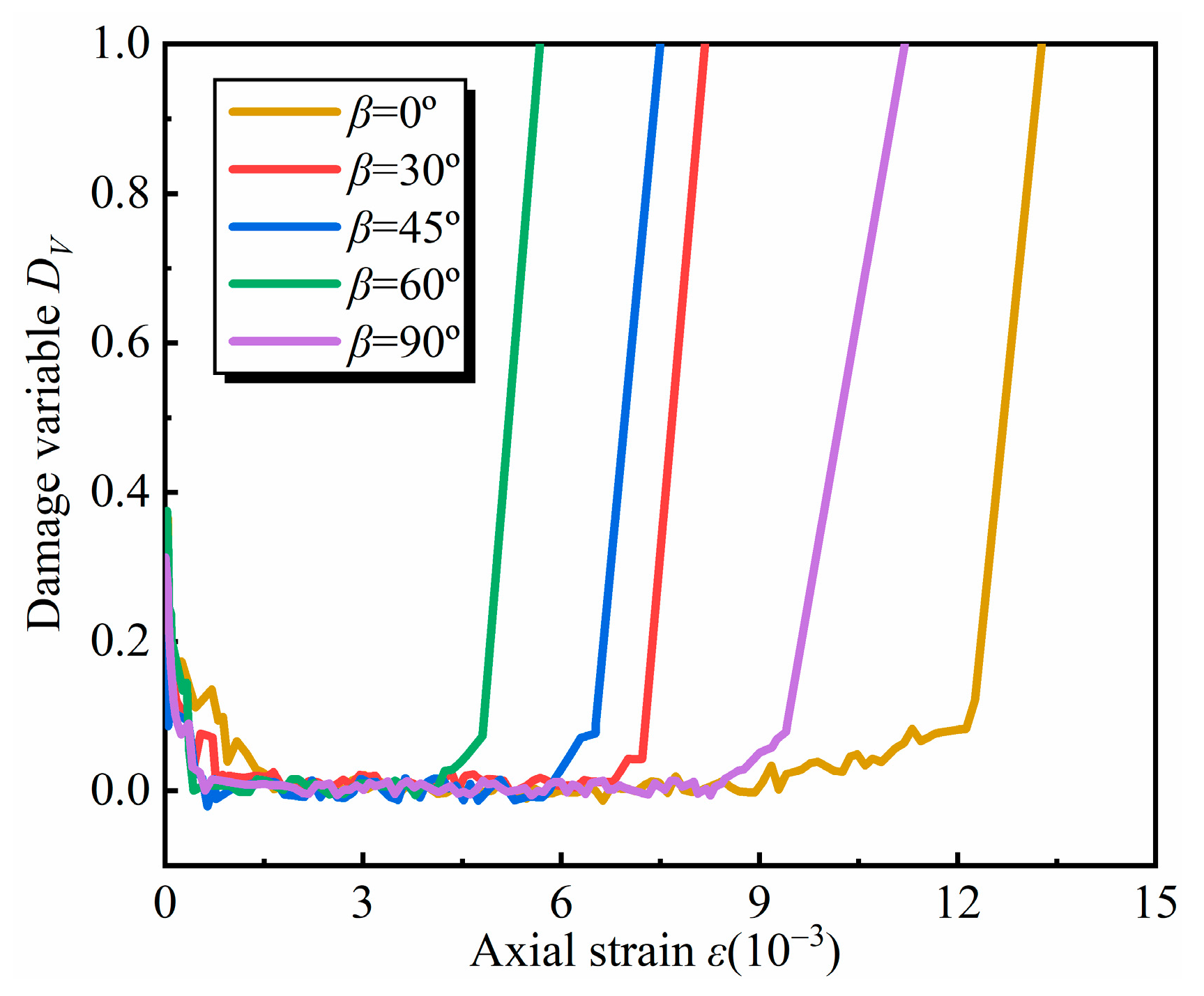
Taking the specimen with a confining pressure of 5 MPa as an example, the evolution of the damage variable DV for rock specimens with different inclinations under the same confining pressure loading is shown in Figure 4.
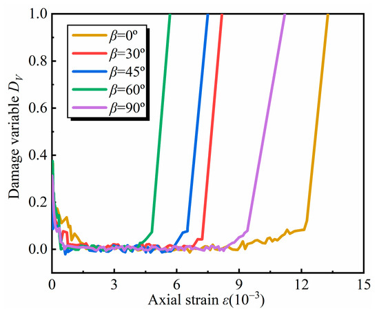
Figure 4.
The influence of inclination on the evolutionary process of the damage variable DV.
The DV-ε curves of specimens inclined at different angles exhibit similar shape characteristics under constant contact pressure. When subjected to the same loading pressure, the strains at 45° and 60° inclination angles are smaller compared to those at 0°, 30°, and 90°. This suggests that the inclination angle of the laminae influences the development of internal damage in the rock, with damage being more likely to occur at 45° and 60° angles.
At a confining pressure of 5 MPa, the initial damage values vary significantly among specimens with different inclination angles. However, the rate of initial damage decrease remains consistent. During both the slow and rapid damage increase stages, the damage development rate is similar across different inclination angles. The anisotropy of peak strength results in varying strain corresponding to the damage change curves during the accelerated rise stage for different inclination angles.
3.2.3. Damage Evolution Laws Based on Wave Velocity
From Figure 4 and Figure 5, it can be seen that the characteristics of the damage variable–strain curve established on the basis of wave velocity can be analyzed in two parts.
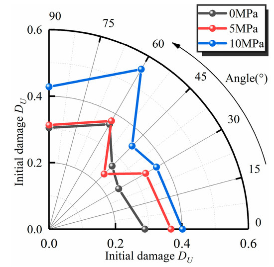
Figure 5.
Relationship between initial damage of specimen and variation in laminar inclination and confining pressure.
Based on the characteristics of the damage variable–strain curve established using wave velocity, no new damage appears within the rock during the first half of the curve. This phenomenon occurs primarily because the initial damage within the rock material is repaired. The value of the damage variable at the intersection of the curve and the y-axis represents the initial damage of the rock specimen. Under the influence of external load, original defects such as microcracks within the rock begin to compress and close, leading to the repair of pre-existing damage and a subsequent numerical decrease in the damage variable. As the stress gradually increases to the crack closure stress, the rate of damage decrease slows, and the slope of the curve approaches zero. Concurrently, the slope of the stress–strain curve increases. Therefore, the first half of the curve can be effectively represented by an inverse proportional function to describe the damage evolution law of the rock.
In the second half of the curve, new damage begins to form and develop slowly within the rock. New microfractures start to appear and expand, causing the value of the damage variable to increase from slow to fast. When the external load reaches the peak strength of the specimen, the rock undergoes brittle damage, and the damage variable rapidly rises to 1, approximating an inclined straight line. This portion of the curve is approximately exponential. Consequently, the rock damage evolution process at this stage can be abstracted as the growth process of a single population in biology. Utilizing a simple continuous growth model in biology, such as the logistic model, where the growth rate varies with the population size, we can establish damage evolution equations with wave velocity as the damage variable.
In the equation, a, b, c, and d are coefficients; εcc is the crack closure strain, which can be determined by VSc; εf is the peak strain, which can be determined by σc.
To check the rationality and reliability of the equations, by analyzing the fitting coefficients and correlation coefficients of the DV-ε data from various specimens, it was found that in the first segmented function fitting results, the correlation coefficient R ranged from a minimum of 0.839 to a maximum of 0.979, with an average value of 0.924. In contrast, the second segmented function fitting results showed a minimum correlation coefficient R of 0.964, a maximum of 0.999, and an average value of 0.990. These findings indicate that the theoretical damage curves, which are based on wave velocity characterization and the rock damage equation using the segmented function, align well with the actual damage observed. Consequently, this approach effectively describes the evolution process between rock damage variables and strain.
3.2.4. Initial Damage Evolution Process
When the confining pressure is constant, the initial damage of specimens with varying laminar inclination angles exhibits anisotropic behavior. Specifically, as the laminar inclination angle increases, the initial damage of the rock first increases and then decreases. The maximum initial damage occurs at a laminar inclination angle of 60°. Additionally, as the confining pressure increases, the initial damage value of specimens with the same inclination angle also increases. Figure 5 illustrates the variations in the initial damage of specimens with different tilt angles under various confining pressures.
4. Discussion
(1) The results of this study elucidate several key aspects of the damage evolution process in layered rocks. Firstly, the damage variables defined based on transverse wave velocity effectively reflect the damage evolution process of layered rock. This finding is particularly important as it underscores the sensitivity of transverse waves to internal changes within the rock structure, which is crucial for understanding damage mechanisms. Moreover, the influence of confining pressure on the damage evolution process is significant. As confining pressure increases, the damage variable–strain curve shifts to the right, indicating that higher pressures lead to greater initial damage. This relationship highlights the necessity of considering confining pressure in the analysis of rock stability and integrity. Additionally, the inclination angle of the slab plays a critical role in the damage evolution process. Under the same confining pressure, samples with inclination angles of 45° and 60° exhibit a higher susceptibility to damage. Interestingly, the initial damage shows a tendency to increase and then decrease, suggesting a complex interaction between the rock’s structural characteristics and the applied stress conditions. These findings are consistent with previous research that has explored the relationship between rock properties and damage evolution [27]. By integrating these insights, this study contributes to a deeper understanding of the damage evolution characteristics of layered rocks, which is essential for engineering safety assessments and the design of rock structures.
(2) Layered rocks have a layered structure and distinct layers that give rise to anisotropic properties. This anisotropy greatly affects the way in which ultrasonic waves propagate through the rock and the response of the rock to the pressure of the surrounding rock. The angle of tilt between the layers and the direction of ultrasonic propagation play a crucial role in determining the behavior of ultrasonic waves in layered rock. If the ultrasonic waves propagate parallel to the plane, they may encounter less resistance and higher velocities due to the orientation of the mineral grains. Conversely, when ultrasonic waves propagate at an angle to the facies, interaction with the layered structure results in an increased scattering and attenuation of the ultrasonic waves. Furthermore, for layered rock, longitudinal and transverse waves are not equally sensitive to level changes. The relationship between longitudinal wave velocity and rock damage characteristics has been extensively studied. Longitudinal wave velocity in a free state reflects rock deformation characteristics and fracture state. However, after fracture closure, the influence of longitudinal waves diminishes significantly. This study, in contrast, finds that transverse waves are more sensitive to these changes [27]. Unlike existing studies on ultrasonic wave velocity [28,29,30,31,32], this paper focuses on the characteristics of ultrasonic waves during damage evolution under various conditions. It defines damage variables and initial damage using ultrasonic transverse wave velocity. Additionally, it analyzes the influence of confining pressure and laminar inclination on the damage evolution of layered rocks.
(3) This study’s results indicate that confining pressure and laminar inclination angle significantly affect the damage evolution process. This effect is likely related to the generation, propagation, and closure of microfractures within the rock. Although transverse wave velocity, which is more sensitive to the internal state of the rock, is used to define initial damage and damage variables, it cannot accurately reflect changes in the fine structure of layered rock from a macroscopic perspective. To bridge this gap, appropriate initial damage and damage variables from fine damage mechanics can be introduced. This approach effectively combines macroscopic and fine damage perspectives, providing a more comprehensive understanding of the damage evolution mechanism in layered rock.
5. Conclusions
In this paper, we conducted a synchronous and isotropic stress wave velocity test experiment to investigate the behavior of slate under loading conditions. By analyzing the changes in wave velocity and the characteristics of the stress–strain curve during the loading process, we defined the crack closure wave velocity as the wave velocity of the rock in an undamaged state. This allowed us to quantitatively characterize the initial damage of the rock. Furthermore, we revealed the damage reduction pattern during the crack compaction stage of the loading process. Our study also addressed the challenge of obtaining the wave velocity of the rock in an undamaged state, which is crucial for determining the damage variable based on wave velocity. The research results indicate the following:
(1) Confining pressure and laminar inclination angle significantly influence the damage evolution process of layered rocks. As confining pressure increases, the damage variable–strain curve shifts to the right. This shift makes the slow-rising stage of damage more pronounced and increases the initial damage. Specimens inclined at 45° and 60° are particularly susceptible to damage. Under the same confining pressure, the initial damage tends to increase and then decrease, peaking at a 60° inclination. This finding demonstrates that the inclination angle of the laminae significantly affects the initial damage of the rock. Additionally, initial damage, as defined by ultrasonic wave velocity, effectively reflects the degree of damage development in the rock.
(2) To accurately describe the evolution process between damage variables and strain during the loading of laminar rock, a segmented damage evolution equation characterized by wave velocity was established. Initially, an inverse proportional function was employed to characterize the strain before crack closure. Subsequently, a logistic function was utilized to represent the curve from crack strain to peak strain. These functions collectively provide a more comprehensive depiction of the relationship between damage variables and strain throughout the loading process.
(3) While this study provides valuable insights, several limitations should be acknowledged. The experiments were conducted on a limited number of samples, which may not fully capture the variability present in natural rock formations. To enhance the generalizability of the results, future studies should consider larger sample sizes and include more highly stratified rocks. Additionally, the tests were performed under controlled laboratory conditions, which may not accurately replicate the complex environmental factors encountered in the field. For instance, the evolution law of the damage variable could be altered under the influence of complex lateral pressure, potentially shifting the damage initiation threshold to higher stress values. Moreover, the interaction between lateral pressure and other factors such as temperature, loading rate, and water content was not investigated. Future research should aim to incorporate field studies or employ more sophisticated laboratory setups that better simulate real-world conditions.
(4) Future studies should compare the effects of longitudinal and transverse wave velocities on damage evolution in layered rocks to achieve a more comprehensive understanding of how different types of waves interact with rock structures. Additionally, it is crucial to conduct field studies to validate laboratory results within natural environments. Such field studies could involve the in situ monitoring of the damage evolution of layered rocks, thereby providing valuable insights into how environmental factors influence the damage process. By integrating laboratory findings with field observations, researchers can develop a more holistic view of the mechanisms driving damage in layered rock formations.
Author Contributions
Conceptualization, J.L. and G.L.; Methodology, G.L.; Formal analysis, S.X. and G.L.; Resources, G.L.; Writing—original draft, J.L. and S.X.; Writing—review & editing, J.L. and G.L.; Supervision, G.L.; Project administration, J.L. All authors have read and agreed to the published version of the manuscript.
Funding
This research received no external funding.
Institutional Review Board Statement
Not applicable.
Informed Consent Statement
Not applicable.
Data Availability Statement
The data presented in this study are available on request from the corresponding author.
Conflicts of Interest
The authors declare no conflict of interest.
References
- Li, D.; Zhou, A.; Wang, L.; Zhang, P. Study on mechanical properties and damage constitutive model of gently inclined layered sandstone under biaxial compression. J. Cent. South Univ. (Sci. Technol.) 2023, 54, 1074–1086. [Google Scholar] [CrossRef]
- Li, X.; Yao, Z.; Liu, X.; Huang, X. Energy Evolution and Damage Mechanism of Fractured Sandstone with Different Angles. Energies 2022, 15, 1518. [Google Scholar] [CrossRef]
- Zhang, L.; Zhang, Z.; Zhang, R.; Gao, M.; Xie, J. The Ultrasonic P-Wave Velocity-Stress Relationship and Energy Evolution of Sandstone under Uniaxial Loading-Unloading Conditions. Adv. Mater. Sci. Eng. 2021, 2021, 9921716. [Google Scholar] [CrossRef]
- Gong, F.; Zhang, P.; Luo, S.; Li, J.; Huang, D. Theoretical Damage Characterisation and Damage Evolution Process of Intact Rocks Based on Linear Energy Dissipation Law under Uniaxial Compression. Int. J. Rock Mech. Min. Sci. 2021, 146, 104858. [Google Scholar] [CrossRef]
- Yin, T.; Men, J.; Lu, J.; Wu, Y.; Guo, W.; Yang, Z.; Ma, J. Study on Dynamic Mechanical Properties and Microscopic Damage Mechanisms of Granite after Dynamic Triaxial Compression and Thermal Treatment. Case Stud. Therm. Eng. 2024, 61, 104910. [Google Scholar] [CrossRef]
- Tian, X.; Tao, T.; Xie, C. Study of Impact Dynamic Characteristics and Damage Morphology of Layered Rock Mass. Geofluids 2022, 2022, 2835775. [Google Scholar] [CrossRef]
- Cheng, Y.; Song, Z.; Yang, T.; Han, J.; Wang, B.; Zhang, Z. Investigating the Aging Damage Evolution Characteristics of Layered Hard Sandstone Using Digital Image Correlation. Constr. Build. Mater. 2022, 353, 128838. [Google Scholar] [CrossRef]
- Xie, Q.; Gao, H.; Ban, Y.; Fu, X.; Liang, X.; Cao, Z.; Duan, J. Influence of Layer Thickness Ratio on the Mechanical and Failure Properties of Soft-Hard Interbedded Rock-like Material. KSCE J. Civ. Eng. 2023, 27, 4962–4977. [Google Scholar] [CrossRef]
- Hao, Y.; Song, X.; Huang, Y.; Zhang, B.; Dong, Z.; Wang, H. Mesoscopic Damage Evolution and Acoustic Emission Characteristics of Cemented Paste Backfill under Different Loading Rates. Environ. Sci. Pollut. Res. 2022, 29, 90686–90702. [Google Scholar] [CrossRef]
- Liu, G.; Zhang, F.; Li, X.; Yang, Z. Research on Large Deformation and its Mechanism of Muzhailing Tunnel. Chin. J. Rock Mech. Eng. 2005, 24, 5521–5526. [Google Scholar]
- Liu, G.; Li, J.; Li, L.; Yang, X.; Yang, X.; Cai, M. Study on Layer Thickness Variation of Stratified Rock Masses under Unloading Conditions. Chin. J. Rock Mech. Eng. 2018, 37, 2772–2784. [Google Scholar] [CrossRef]
- Xu, X.; Yue, C.; Xu, L. Thermal Damage Constitutive Model and Brittleness Index Based on Energy Dissipation for Deep Rock. Mathematics 2022, 10, 410. [Google Scholar] [CrossRef]
- Energy Evolution and Damage Constitutive Model of Anchored Jointed Rock Masses under Static and Fatigue Loads. Int. J. Fatigue 2023, 167, 107313. [CrossRef]
- Huang, S.; Zhang, J.; Ding, X.; Zhang, C.; Han, G.; Yu, G.; Qu, L. Investigation of Anisotropic Strength Criteria for Layered Rock Mass. J. Rock Mech. Geotech. Eng. 2024, 16, 1289–1304. [Google Scholar] [CrossRef]
- Bai, Q.; Dai, H. Numerical Simulation on Characteristics of Damage and Failure of Layered Rock Mass. J. Yangtze River Sci. Res. Inst. 2022, 39, 129–134. [Google Scholar] [CrossRef]
- Song, Z.; Cheng, J.; Yang, T.; Yang, P.; Pan, H. Experimental Study on Fatigue Damage Evolution Mechanism of Hard Layered Sandstone under Cyclic Loading. Chin. J. Geotech. Eng. 2024, 46, 490–499. [Google Scholar] [CrossRef]
- Liu, D.; Guo, Y.; Li, J.; Ling, K. Damage Constitutive Model for Layered Yellow Sandstone Based on Dissipative Energy Evolution and its Verification. Chin. J. Eng. 2024, 46, 784–799. [Google Scholar] [CrossRef]
- Kawamoto, T.; Ichikawa, Y.; Kyoya, T. Deformation and Fracturing Behaviour of Discontinuous Rock Mass and Damage Mechanics Theory. Int. J. Numer. Anal. Met. 1988, 12, 1–30. [Google Scholar] [CrossRef]
- Feng, W.; Qiao, C.; Niu, S.; Yang, Z.; Wang, T. An Improved Nonlinear Damage Model of Rocks Considering Initial Damage and Damage Evolution. Int. J. Damage Mech. 2020, 29, 1117–1137. [Google Scholar] [CrossRef]
- Hou, R.; Zhang, K.; Tao, J.; Xue, X.; Chen, Y. A Nonlinear Creep Damage Coupled Model for Rock Considering the Effect of Initial Damage. Rock Mech. Rock Eng. 2019, 52, 1275–1285. [Google Scholar] [CrossRef]
- Zhang, M.; Xu, R. The Rock Damage and Strength Study Based on Ultrasonic Velocity. Chin. J. Geotech. Eng. 2000, 22, 720–722. [Google Scholar]
- Zhao, M.; Wu, D. Ultrasonic Velocity and Attenuation of Rocks under Uniaxial Loading. Chin. J. Rock Mech. Eng. 1999, 18, 51–55. [Google Scholar]
- Wang, S.; Zhang, M.; Jiang, S.; Yi, L.; Lin, Z. Analysis of Tunnel Rock Damage Evolution Process in Excavation and Predicting Mechanical Parameters. Rock Soil Mech. 2009, 30, 195–200. [Google Scholar] [CrossRef]
- Yang, Z.; Qi, X.; Feng, M.; Wang, W.; Fu, P. Mechanical Damage Test and Modelling of Layered Composite Rock Based on Acoustic Emission and DIC Characteristics. J. Chang. River Sci. Res. Inst. 2023, 40, 119–126. [Google Scholar]
- Wang, P.; Ma, C.; Cai, M. Relationships between Rock Ultrasonic Properties with Loading Stresses and Challenges in Deep Mining. J. Cent. South Univ. 2023, 30, 3737–3762. [Google Scholar] [CrossRef]
- Lemaitre, J.; Chaboche, J.L. Aspect Phénoménologique de La Ruptare Par Endommagement. J. Méc. Appl. 1978, 2, 167–189. [Google Scholar]
- Sarout, J.; Molez, L.; Guéguen, Y.; Hoteit, N. Shale Dynamic Properties and Anisotropy under Triaxial Loading: Experimental and Theoretical Investigations. Phys. Chem. Earth Parts A/B/C 2007, 32, 896–906. [Google Scholar] [CrossRef]
- You, M.; Su, C.; Li, X. Study of the Relationship between Mechanical Properties and Longitudinal Wave Velocitys for Damaged Rock Samples. Chin. J. Rock Mech. Eng. 2008, 458–467. [Google Scholar] [CrossRef]
- Hu, M.; Zhou, H.; Zhang, Y.; Zhang, C.; Gao, Y.; Hu, D.; Lu, J. Analysis of Acoustic Property of Sandstone under Uniaxial Loading. Rock Soil Mech. 2018, 39, 4468–4474. [Google Scholar] [CrossRef]
- Sun, B.; Ren, F.; Liu, D. Research on the Failure Precursors of Layered Slate Based on Multifractal Characteristics of Acoustic Emission. Rock Soil Mech. 2022, 43, 749–760. [Google Scholar] [CrossRef]
- Yuan, W.; Cheng, Y.; Min, M.; Wang, X. Study on Acoustic Emission Characteristics during Shear Deformation of Rock Structural Planes Based on Particle Flow Code. Comput. Part Mech. 2024, 11, 105–118. [Google Scholar] [CrossRef]
- Chen, T.; Zhao, K.; Yan, Y.; Zhou, Y.; He, Z.; Guo, L. Mechanical Properties and Acoustic Emission Response of Cemented Tailings Backfill under Variable Angle Shear. Constr. Build. Mater. 2022, 343, 128114. [Google Scholar] [CrossRef]


Disclaimer/Publisher’s Note: The statements, opinions and data contained in all publications are solely those of the individual author(s) and contributor(s) and not of MDPI and/or the editor(s). MDPI and/or the editor(s) disclaim responsibility for any injury to people or property resulting from any ideas, methods, instructions or products referred to in the content. |
© 2024 by the authors. Licensee MDPI, Basel, Switzerland. This article is an open access article distributed under the terms and conditions of the Creative Commons Attribution (CC BY) license (https://creativecommons.org/licenses/by/4.0/).